EP0979686A2 - Poröser Piezoelektische-keramikschicht und PiezoelectrischerWandler - Google Patents
Poröser Piezoelektische-keramikschicht und PiezoelectrischerWandler Download PDFInfo
- Publication number
- EP0979686A2 EP0979686A2 EP99115155A EP99115155A EP0979686A2 EP 0979686 A2 EP0979686 A2 EP 0979686A2 EP 99115155 A EP99115155 A EP 99115155A EP 99115155 A EP99115155 A EP 99115155A EP 0979686 A2 EP0979686 A2 EP 0979686A2
- Authority
- EP
- European Patent Office
- Prior art keywords
- piezoelectric
- ceramic sheet
- porous
- transducer
- range
- Prior art date
- Legal status (The legal status is an assumption and is not a legal conclusion. Google has not performed a legal analysis and makes no representation as to the accuracy of the status listed.)
- Withdrawn
Links
- 239000000919 ceramic Substances 0.000 title claims abstract description 64
- 239000011148 porous material Substances 0.000 claims abstract description 36
- 229910020294 Pb(Zr,Ti)O3 Inorganic materials 0.000 claims abstract description 3
- 230000010287 polarization Effects 0.000 claims description 6
- 238000004519 manufacturing process Methods 0.000 abstract description 2
- 239000000463 material Substances 0.000 description 25
- 229910052451 lead zirconate titanate Inorganic materials 0.000 description 17
- 239000000843 powder Substances 0.000 description 11
- 238000007689 inspection Methods 0.000 description 6
- 239000000523 sample Substances 0.000 description 6
- 230000035945 sensitivity Effects 0.000 description 6
- 239000011521 glass Substances 0.000 description 5
- HFGPZNIAWCZYJU-UHFFFAOYSA-N lead zirconate titanate Chemical compound [O-2].[O-2].[O-2].[O-2].[O-2].[Ti+4].[Zr+4].[Pb+2] HFGPZNIAWCZYJU-UHFFFAOYSA-N 0.000 description 5
- 239000002245 particle Substances 0.000 description 5
- 229920003229 poly(methyl methacrylate) Polymers 0.000 description 5
- 239000000126 substance Substances 0.000 description 5
- BQCADISMDOOEFD-UHFFFAOYSA-N Silver Chemical compound [Ag] BQCADISMDOOEFD-UHFFFAOYSA-N 0.000 description 4
- 239000002184 metal Substances 0.000 description 4
- 229910052751 metal Inorganic materials 0.000 description 4
- 229910052709 silver Inorganic materials 0.000 description 4
- 239000004332 silver Substances 0.000 description 4
- XLYOFNOQVPJJNP-UHFFFAOYSA-N water Substances O XLYOFNOQVPJJNP-UHFFFAOYSA-N 0.000 description 4
- -1 PZT) Chemical compound 0.000 description 3
- 239000004372 Polyvinyl alcohol Substances 0.000 description 3
- 239000011230 binding agent Substances 0.000 description 3
- 229910010293 ceramic material Inorganic materials 0.000 description 3
- 238000010438 heat treatment Methods 0.000 description 3
- 239000007788 liquid Substances 0.000 description 3
- 239000000203 mixture Substances 0.000 description 3
- 239000004926 polymethyl methacrylate Substances 0.000 description 3
- 229920002451 polyvinyl alcohol Polymers 0.000 description 3
- 238000007650 screen-printing Methods 0.000 description 3
- 239000013077 target material Substances 0.000 description 3
- 239000002131 composite material Substances 0.000 description 2
- 230000007547 defect Effects 0.000 description 2
- 238000001514 detection method Methods 0.000 description 2
- 238000000034 method Methods 0.000 description 2
- 238000002156 mixing Methods 0.000 description 2
- 229920003023 plastic Polymers 0.000 description 2
- 239000004033 plastic Substances 0.000 description 2
- 238000002360 preparation method Methods 0.000 description 2
- 230000000644 propagated effect Effects 0.000 description 2
- 238000005245 sintering Methods 0.000 description 2
- 239000002002 slurry Substances 0.000 description 2
- YCKRFDGAMUMZLT-UHFFFAOYSA-N Fluorine atom Chemical compound [F] YCKRFDGAMUMZLT-UHFFFAOYSA-N 0.000 description 1
- 229910020279 Pb(Zr, Ti)O3 Inorganic materials 0.000 description 1
- 239000011358 absorbing material Substances 0.000 description 1
- 239000012736 aqueous medium Substances 0.000 description 1
- 229910002113 barium titanate Inorganic materials 0.000 description 1
- JRPBQTZRNDNNOP-UHFFFAOYSA-N barium titanate Chemical compound [Ba+2].[Ba+2].[O-][Ti]([O-])([O-])[O-] JRPBQTZRNDNNOP-UHFFFAOYSA-N 0.000 description 1
- 230000017531 blood circulation Effects 0.000 description 1
- 238000009835 boiling Methods 0.000 description 1
- 239000011248 coating agent Substances 0.000 description 1
- 238000000576 coating method Methods 0.000 description 1
- 150000001875 compounds Chemical class 0.000 description 1
- 230000008878 coupling Effects 0.000 description 1
- 238000010168 coupling process Methods 0.000 description 1
- 238000005859 coupling reaction Methods 0.000 description 1
- 239000013078 crystal Substances 0.000 description 1
- 230000006378 damage Effects 0.000 description 1
- 230000003247 decreasing effect Effects 0.000 description 1
- 230000002950 deficient Effects 0.000 description 1
- 230000001066 destructive effect Effects 0.000 description 1
- 239000003989 dielectric material Substances 0.000 description 1
- NKZSPGSOXYXWQA-UHFFFAOYSA-N dioxido(oxo)titanium;lead(2+) Chemical compound [Pb+2].[O-][Ti]([O-])=O NKZSPGSOXYXWQA-UHFFFAOYSA-N 0.000 description 1
- 239000007772 electrode material Substances 0.000 description 1
- 230000001747 exhibiting effect Effects 0.000 description 1
- 229910052731 fluorine Inorganic materials 0.000 description 1
- 239000011737 fluorine Substances 0.000 description 1
- 239000012774 insulation material Substances 0.000 description 1
- 239000002609 medium Substances 0.000 description 1
- 239000007769 metal material Substances 0.000 description 1
- 238000000465 moulding Methods 0.000 description 1
- 238000005498 polishing Methods 0.000 description 1
- 229920000642 polymer Polymers 0.000 description 1
- 239000002861 polymer material Substances 0.000 description 1
- 239000002952 polymeric resin Substances 0.000 description 1
- 238000003825 pressing Methods 0.000 description 1
- 239000010453 quartz Substances 0.000 description 1
- 230000000979 retarding effect Effects 0.000 description 1
- VYPSYNLAJGMNEJ-UHFFFAOYSA-N silicon dioxide Inorganic materials O=[Si]=O VYPSYNLAJGMNEJ-UHFFFAOYSA-N 0.000 description 1
- 238000005507 spraying Methods 0.000 description 1
- 238000004544 sputter deposition Methods 0.000 description 1
- 229920003002 synthetic resin Polymers 0.000 description 1
- 238000007740 vapor deposition Methods 0.000 description 1
Images


Classifications
-
- H—ELECTRICITY
- H10—SEMICONDUCTOR DEVICES; ELECTRIC SOLID-STATE DEVICES NOT OTHERWISE PROVIDED FOR
- H10N—ELECTRIC SOLID-STATE DEVICES NOT OTHERWISE PROVIDED FOR
- H10N30/00—Piezoelectric or electrostrictive devices
- H10N30/80—Constructional details
- H10N30/85—Piezoelectric or electrostrictive active materials
- H10N30/853—Ceramic compositions
Definitions
- the present invention relates to a porous piezoelectric ceramic sheet and a piezoelectric transducer.
- the invention relates to a porous piezoelectric lead zirconate titanate ceramic sheet and a piezoelectric transducer using the porous lead zirconate titanate ceramic sheet.
- Ultrasonic wave is propagated through material and reflected on an interface between the material and a foreign substance or a vacancy contained in the material, because such foreign substance and vacancy shows an acoustic impedance differing from that of the material. Utilizing this characteristic, ultrasonic wave can be employed for detecting foreign substances and defects in the target material without destruction of the target material. Accordingly, non-destructive inspection using ultrasonic wave is used in a variety of technical fields such as diagnostics, inspections of metallic material, inspections of buildings, and detections of a group of fishes in the seas or lakes.
- the ultrasonic wave can be produced by applying a voltage of a high frequency to a piezoelectric transducer which is manufactured by placing an electrode on each surface side of a piezoelectric sheet and then applying a voltage between these electrodes.
- the piezoelectric transducer receives a reflected ultrasonic wave and convert the received ultrasonic wave to electric signals.
- the piezoelectric sheet can be formed of a single crystal such as crystallized quartz, a sintered piezoelectric ceramic, a piezoelectric polymer material, and a mixture of a piezoelectric ceramic and a polymer resin.
- a piezoelectric sheet of sintered piezoelectric ceramic is widely employed for manufacture of a piezoelectric transducer because it gives a high electro-mechanical coupling factor.
- the piezoelectric ceramics include barium titanate, lead titanate, and lead zirconate titanate (Pb(Zr, Ti)O 3 ), which is generally referred to as PZT or P-PZT (i.e., piezoelectric PZT). PZT is most widely utilized.
- the piezoelectric sheet to be employed as a source of ultrasonic wave in a ultrasonic detector preferably shows an acoustic impedance similar to that of the material to be inspected. Further, it is preferred for the piezoelectric sheet to emit a ultrasonic wave having a mono pulse wave form so that the defects and foreign substances in the inspected material are accurately detected.
- an acoustic impedance-adjusting material is conventionally attached to a piezoelectric transducer of the inspection equipment.
- the adjustment of acoustic impedance using the acoustic impedance-adjusting material is limitative.
- a porous piezoelectric PZT ceramic transducer exhibiting improved characteristics such as a large piezoelectric voltage coefficient (g constant), a low acoustic impedance (Z 0 ) and a low Q.
- a sintered PZT disk having a diameter of 50 mm and a thickness of 8 mm is prepared by mixing powders of PZT and PMMA (poly(methyl methacrylate)) having average particle sizes of 1.2 ⁇ m and 30 ⁇ m, pressing the mixture to form a disc, heating the disc to 400°C to burn out PMMA and finally sintering the heated disc.
- Japanese Patent Provisional Publication No. 1-172281 describes a porous dielectric material for piezoelectric transducer having pore volume of 23 to 45% and main pores having a size of 20 to 44 ⁇ m. No mention is given with respect to the preparation of a thin piezoelectric sheet.
- Japanese Patent Provisional Publication No. 1-171281 describes a porous piezoelectric transducer having a coat of glass material on each surface side and an electrode on each glass material coat.
- Japanese Patent Provisional Publication No. 4-300253 describes a process for producing a porous piezoelectric element using a PZT powder, a binder, and a combustible polymer powder. No mention is given with respect to the preparation of a thin piezoelectric sheet.
- a ultrasonic wave having a frequency of 1 to 30 MHz is employed.
- a piezoelectric transducer In order to emit a ultrasonic wave of a frequency of 1-30 MHz, a piezoelectric transducer should have a piezoelectric sheet of 0.05 to 2.0 mm thick. Moreover, the piezoelectric transducer having such a small thickness still has a uniform piezoelectric characteristic within the piezoelectric sheet.
- porous piezoelectric ceramic sheet having a thickness in the range of 0.05 to 2 mm and comprising Pb(Zr,Ti)O 3 , namely, lead zirconate titanate (i.e., PZT), which has pores essentially all of which have a size of less than 25 ⁇ m in which pores having a size in the range of 5 to 25 ⁇ m have a mean pore size in the range of 1/10 to 1/1,000 based on the thickness of the ceramic sheet, and which shows a ratio of apparent density to true density in the range of 5/10 to 9/10.
- Pb(Zr,Ti)O 3 namely, lead zirconate titanate (i.e., PZT)
- the lead zirconate titanate may comprise a small amount of oxides and may comprise a piezoelectric perovskite ceramic.
- the sizes of the pores in the porous piezoelectric ceramic sheet of the invention are determined by enlarging the surface of the porous sheet by electron microscopic picture to 200 magnifications (x 200) or more, measuring sizes of the pores seen in the enlarged picture using a measuring apparatus such as slide calipers, and dividing the measured sizes by the magnification value.
- the average size is expressed in terms of arithmetic average.
- the invention further provides a piezoelectric transducer utilizing the above-mentioned porous piezoelectric ceramic sheet.
- the invention furthermore provides an array of the above-mentioned piezoelectric transducers.
- the porous piezoelectric ceramic sheet at the invention has extremely small pores which are dispersed in the ceramic sheet uniformly.
- the porous piezoelectric ceramic sheet of the invention has a thickness of 0.05 to 2 mm, preferably 0.1 to 2 mm, more preferably 0.1 to 1.0 mm, most preferably 0.1 to 0.6 mm.
- a ratio of apparent density to true density of the porous piezoelectric ceramic sheet is in the range of 5/10 to 9/10.
- the pores in the porous piezoelectric ceramic sheet of the invention satisfy the following conditions:
- the thin porous piezoelectric ceramic sheet of the present invention can be prepared by the process which comprises:
- the piezoelectric transducer of the invention typically has a section illustrated in Figs. 2 and 3 in the attached drawing.
- the piezoelectric transducer of Fig. 2 is prepared by placing on each surface side of the thin porous piezoelectric ceramic sheet 1 of the invention (comprising piezoelectric material 2a and small pores 2b) an electrode 3 by screen printing, sputtering or vapor deposition.
- the printed electrode is generally heated to a temperature of 600 to 800°C.
- the porous piezoelectric ceramic sheet is then polarized by applying a voltage between the electrodes.
- the polarization of the porous piezoelectric transducer is preferably carried out in a volatile liquid medium having a boiling point higher than the polarizing temperature (generally in the range of 50 to 150°C) and lower than a Curie temperature of the piezoelectric ceramic material.
- the volatile liquid mediums include fluorine-containing liquid compounds.
- the polarization may be performed in air by applying a voltage of less than 1 kV/mm between the electrodes.
- the piezoelectric transducer of Fig. 3 is prepared by coating on each surface side of the thin porous piezoelectric ceramic sheet 1 of the invention (comprising piezoelectric material 2a and small pores 2b) a layer of insulating glass material 4, and then placing an electrode 3 on each glass material coat.
- the coat of glass material serves to keep the electrode material from entering the pores of the porous piezoelectric ceramic sheet so that the piezoelectric characteristic of the piezoelectric transducer can be maintained uniform in the plane direction.
- the porous piezoelectric ceramic sheet is then polarized by applying a voltage between the electrodes.
- Fig. 4 illustrates an array of piezoelectric transducers 6 which are manufactured utilizing a porous piezoelectric ceramic sheet of the invention.
- a piezoelectric transducer 5 comprising the porous piezoelectric ceramic sheet 1 and a pair of electrodes 3 has on the upper electrode an acoustic impedance-adjusting layer 8. Since each of the porous piezoelectric sheet has the conditions of the invention, the piezoelectric transducers in the array show equivalent piezoelectric characteristics.
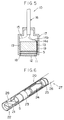
- the piezoelectric transducer of the invention can be utilized in a variety of ultrasonic testing or measuring apparatuses. Their examples are illustrated in Fig. 5 to 10 of the attached drawings.
- Fig. 5 is a schematic sectional view of a probe (of single element type) 10 of a ultrasonic diagnostic equipment.
- the probe 10 has the piezoelectric transducer 5 of the invention in a casing 17 (made of metal) at the opening 18 of the casing.
- an acoustic impedance-adjusting layer 11 is provided under the transducer 5.
- an acoustic lens 12 is placed under the adjusting layer 11, an acoustic lens 12 is placed.
- a damper material layer 13 is placed on the transducer 5.
- a cable 16 is inserted from the top opening of the casing. From the cable 16, lead wires 14a, 14b are drawn to connect to both electrodes of the transducer 5, respectively.
- An earth wire 15 is also drawn from the cable 16 and attached to the casing 17.
- the composite of the piezoelectric transducer 5, adjusting layer 11 and damper material layer 13 is shielded from the metal casing 17 by an insulating wall 19.
- Fig. 6 is a partly broken schematic view of a catheter probe 20 of a ultrasonic diagnostic equipment utilizing the piezoelectric transducer.
- the catheter prove 20 has the piezoelectric transducer 5 in a cylindrical casing 27 which has an acoustic winder 28 on a side wall of the casing.
- the cylindrical casing 27 comprises a plastic inner tube 15 and a plastic covering tube 26. Between the transducer 5 and the inner tube 15 are provided a bearing 23 and a rotatable axis 24 which serve in cooperation to rotate the transducer 5 within the cylindrical casing 27.
- a ultrasonic wave transmitting and receiving area 22 having a mirror 21, which is rotatable in combination with the transducer 5.
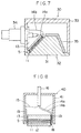
- Fig. 7 is a schematic sectional view of the piezoelectric transducer 30 for a ultrasonic flow meter.
- the piezoelectric transducer 30 has the piezoelectric transducer 5 of the invention in a casing 33. Under the transducer 5, an acoustic impedance-adjusting layer 11 is provided. On the transducer 5 is provided a damper material layer 13. On the bottom of the casing 33, there is provided a combination of a wedge 31 and a bottom plate 32. On the wedge 31, a acoustic-absorbing material layer 35 is placed. From the side wall of the casing 33, a connector 34 which is connected to an outer flow meter (not illustrated). From the connector 34, two lead wires 14a, 14b are drawn to connect to the electrodes of the transducer 5.
- Fig. 8 is a schematic sectional view of the piezoelectric transducer means 40 for a ultrasonic testing apparatus.
- the transducer means (probe) 40 has the piezoelectric transducer 5 in a casing 41 (made of metal) at the opening 18 of the casing.
- an acoustic impedance-adjusting layer 11 is provided under the transducer 5.
- an acoustic lens 12 is placed on the transducer 5, a damper material layer 13 is placed.
- a cable 16 is inserted from the top opening of the casing. From the cable 16, two lead wires 14a, 14b are drawn to connect to both electrodes of the transducer 5, respectively.
- An earth wire 15 is also drawn from the cable 16 and attached to the casing 41.
- the composite of the piezoelectric transducer 5, adjusting layer 11 and damper material layer 13 is shielded from the metal casing 41 by an insulating wall 19.
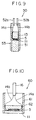
- Fig. 9 is a schematic sectional view of a piezoelectric transducer means 50 for a ultrasonic thickness meter.
- the transducer means 50 has a piezoelectric transducer element 5 of the invention in a cylindrical casing 53. Under the transducer 5, an acoustic impedance-adjusting layer 11 is provided. Under the adjusting layer 11, an acoustic retarding material 51 is placed. On the transducer 5, a damper material layer 13 is placed. A pair of connecting pins 52a, 52b are inserted from the top opening of the casing. From each of the connecting pins 52a, 52b, two lead wires 14a, 14b are drawn to connect to both electrodes of the transducer 5, respectively.
- Fig. 10 is a schematic sectional view of a piezoelectric transducer means 60 of the invention for a ultrasonic bubble-detecting apparatus.
- the transducer means 60 has a piezoelectric transducer element 5 of the invention in a casing 61. Under the transducer 5, an acoustic impedance-adjusting layer 11 is provided. On the transducer 5, a noise insulation material layer 62 is placed. A cable 16 is inserted from the top opening of the casing. From each of the cable 16, two lead wires 14a, 14b are drawn to connect to both electrodes of the transducer 5, respectively.
- Typical examples of detecting or testing apparatuses utilizing a piezoelectric transducer of the invention have been described by referring to the attached drawings.
- the piezoelectric transducer of the invention can be utilizable in a variety of detecting or testing apparatuses other than these illustrated.
- Exampies of the other apparatuses include a communicator utilizing ultrasonic wave to be employed in water such as in sea, and a multilayer actuator comprising a laminated piezoelectric transducers.
- the surface of the thin porous sheet was checked by electron microscopic observation using an electron macroscopic apparatus (JSM-5310, Japan Electron Co., Ltd.). The microscopic photograph is given in Fig. 1 of the attached drawings. It was confirmed that almost all pores are uniformly dispersed in the porous sheet. It was also confirmed that all pores had a pore size less than 15 ⁇ m, an average size of pores having a pore size range of 5 to 15 ⁇ m was 10 ⁇ m.
- the apparent density of the thin porous sheet was 6.0 g/cm 3 , while its true density was 7.7 g/cm 3 .
- the thin porous piezoelectric sheet produced in Example 1 was further polished to give a thinner porous piezoelectric sheet of 0.238 mm thick.
- On both surface of the thinner porous sheet was placed an electroconductive silver paste by screen printing.
- the printed silver paste was heated to 700°C to form an electrode on each side.
- a voltage of 0.5 kV/mm was applied between the two electrodes to polarize the porous sheet.
- a piezoelectric transducer showing a resonance frequency of 5 MHz was prepared.
Landscapes
- Chemical & Material Sciences (AREA)
- Engineering & Computer Science (AREA)
- Ceramic Engineering (AREA)
- Transducers For Ultrasonic Waves (AREA)
- Compositions Of Oxide Ceramics (AREA)
Applications Claiming Priority (2)
| Application Number | Priority Date | Filing Date | Title |
|---|---|---|---|
| JP24258498 | 1998-08-12 | ||
| JP24258498 | 1998-08-12 |
Publications (2)
| Publication Number | Publication Date |
|---|---|
| EP0979686A2 true EP0979686A2 (de) | 2000-02-16 |
| EP0979686A3 EP0979686A3 (de) | 2002-02-06 |
Family
ID=17091242
Family Applications (1)
| Application Number | Title | Priority Date | Filing Date |
|---|---|---|---|
| EP99115155A Withdrawn EP0979686A3 (de) | 1998-08-12 | 1999-08-12 | Poröser Piezoelektische-keramikschicht und PiezoelectrischerWandler |
Country Status (2)
| Country | Link |
|---|---|
| US (1) | US6111339A (de) |
| EP (1) | EP0979686A3 (de) |
Cited By (3)
| Publication number | Priority date | Publication date | Assignee | Title |
|---|---|---|---|---|
| US20130026108A1 (en) * | 2011-05-31 | 2013-01-31 | Empire Technology Development Llc | Piezoelectric discharge water purification |
| US20170317269A1 (en) * | 2014-11-12 | 2017-11-02 | The Trustees Of Dartmouth College | Porous piezoelectric material with dense surface, and associated methods and devices |
| CN110813683A (zh) * | 2019-10-14 | 2020-02-21 | 中国石油天然气集团有限公司 | 一种随钻声波远探测低频发射换能器 |
Families Citing this family (24)
| Publication number | Priority date | Publication date | Assignee | Title |
|---|---|---|---|---|
| GB9921982D0 (en) * | 1999-09-16 | 1999-11-17 | Secretary Trade Ind Brit | Cavitation sensor |
| EP1282174B1 (de) * | 2001-07-27 | 2008-06-18 | Holmberg GmbH & Co. KG | Schwingungswandler mit piezoelektrischem Element |
| US7057480B2 (en) * | 2002-09-17 | 2006-06-06 | M/A-Com, Inc. | Cross-coupled dielectric resonator circuit |
| US7310031B2 (en) * | 2002-09-17 | 2007-12-18 | M/A-Com, Inc. | Dielectric resonators and circuits made therefrom |
| US20040115396A1 (en) * | 2002-12-13 | 2004-06-17 | Palo Alto Research Center, Inc. | Product and process for bonding porous materials to substrates |
| US20040257176A1 (en) * | 2003-05-07 | 2004-12-23 | Pance Kristi Dhimiter | Mounting mechanism for high performance dielectric resonator circuits |
| US20050200437A1 (en) * | 2004-03-12 | 2005-09-15 | M/A-Com, Inc. | Method and mechanism for tuning dielectric resonator circuits |
| US7088203B2 (en) * | 2004-04-27 | 2006-08-08 | M/A-Com, Inc. | Slotted dielectric resonators and circuits with slotted dielectric resonators |
| US20060042455A1 (en) * | 2004-08-31 | 2006-03-02 | Schatten Leslie M | Piezoelectric transducer for stringed musical instruments |
| US7388457B2 (en) | 2005-01-20 | 2008-06-17 | M/A-Com, Inc. | Dielectric resonator with variable diameter through hole and filter with such dielectric resonators |
| US7583164B2 (en) * | 2005-09-27 | 2009-09-01 | Kristi Dhimiter Pance | Dielectric resonators with axial gaps and circuits with such dielectric resonators |
| US7352264B2 (en) * | 2005-10-24 | 2008-04-01 | M/A-Com, Inc. | Electronically tunable dielectric resonator circuits |
| US7705694B2 (en) * | 2006-01-12 | 2010-04-27 | Cobham Defense Electronic Systems Corporation | Rotatable elliptical dielectric resonators and circuits with such dielectric resonators |
| US7719391B2 (en) * | 2006-06-21 | 2010-05-18 | Cobham Defense Electronic Systems Corporation | Dielectric resonator circuits |
| US20080272860A1 (en) * | 2007-05-01 | 2008-11-06 | M/A-Com, Inc. | Tunable Dielectric Resonator Circuit |
| US7456712B1 (en) * | 2007-05-02 | 2008-11-25 | Cobham Defense Electronics Corporation | Cross coupling tuning apparatus for dielectric resonator circuit |
| US8210046B2 (en) * | 2007-08-17 | 2012-07-03 | Ge Inspection Technologies, Lp | Composition for acoustic damping |
| WO2009046736A1 (en) * | 2007-10-08 | 2009-04-16 | Siemens Aktiengesellschaft | Piezo-electric crystal |
| DE102008055116A1 (de) * | 2008-12-23 | 2010-07-01 | Robert Bosch Gmbh | Verfahren zur Herstellung eines Ultraschallwandlers |
| WO2011083611A1 (ja) * | 2010-01-06 | 2011-07-14 | テイカ株式会社 | コンポジット圧電体とそのコンポジット圧電体の製造方法およびそのコンポジット圧電体を用いたコンポジット圧電素子 |
| WO2013026125A1 (en) | 2011-08-24 | 2013-02-28 | National Research Council Of Canada | Porosity control in piezoelectric films |
| CN112236877A (zh) * | 2018-07-17 | 2021-01-15 | 永井清 | 多孔压电材料成型体、其制造方法以及使用该成型体的探头 |
| RU197428U1 (ru) * | 2019-11-25 | 2020-04-24 | федеральное государственное автономное образовательное учреждение высшего образования «Южный федеральный университет» | Пьезоэлектрический гидроакустический преобразователь |
| US11746062B2 (en) | 2020-03-19 | 2023-09-05 | Airmar Technology Corporation | Processes for preparing porous ceramics for acoustic transducers |
Family Cites Families (6)
| Publication number | Priority date | Publication date | Assignee | Title |
|---|---|---|---|---|
| DE3430161A1 (de) * | 1984-08-16 | 1986-02-27 | Siemens AG, 1000 Berlin und 8000 München | Poroese anpassungsschicht in einem ultraschallapplikator |
| US4777153A (en) * | 1986-05-06 | 1988-10-11 | Washington Research Foundation | Process for the production of porous ceramics using decomposable polymeric microspheres and the resultant product |
| US4914565A (en) * | 1987-05-22 | 1990-04-03 | Siemens Aktiengesellschaft | Piezo-electric transducer having electrodes that adhere well both to ceramic as well as to plastics |
| DE3724290A1 (de) * | 1987-07-22 | 1989-02-02 | Siemens Ag | Elektrode fuer piezoelektrische composites |
| JP2745147B2 (ja) * | 1989-03-27 | 1998-04-28 | 三菱マテリアル 株式会社 | 圧電変換素子 |
| US6022584A (en) * | 1995-11-15 | 2000-02-08 | The United States Of America As Represented By The Secretary Of The Navy | Making large porous aggregates |
-
1999
- 1999-08-12 EP EP99115155A patent/EP0979686A3/de not_active Withdrawn
- 1999-08-12 US US09/373,332 patent/US6111339A/en not_active Expired - Lifetime
Cited By (5)
| Publication number | Priority date | Publication date | Assignee | Title |
|---|---|---|---|---|
| US20130026108A1 (en) * | 2011-05-31 | 2013-01-31 | Empire Technology Development Llc | Piezoelectric discharge water purification |
| US9512013B2 (en) * | 2011-05-31 | 2016-12-06 | Empire Technology Development Llc | Piezoelectric discharge water purification |
| US20170317269A1 (en) * | 2014-11-12 | 2017-11-02 | The Trustees Of Dartmouth College | Porous piezoelectric material with dense surface, and associated methods and devices |
| US10147870B2 (en) * | 2014-11-12 | 2018-12-04 | The Trustees Of Dartmouth College | Porous piezoelectric material with dense surface, and associated methods and devices |
| CN110813683A (zh) * | 2019-10-14 | 2020-02-21 | 中国石油天然气集团有限公司 | 一种随钻声波远探测低频发射换能器 |
Also Published As
| Publication number | Publication date |
|---|---|
| EP0979686A3 (de) | 2002-02-06 |
| US6111339A (en) | 2000-08-29 |
Similar Documents
| Publication | Publication Date | Title |
|---|---|---|
| US6111339A (en) | Porous piezoelectric ceramic sheet and piezoelectric transducer | |
| CA2248801C (en) | Improved piezoelectric ceramic-polymer composites | |
| US6215231B1 (en) | Hollow sphere transducers | |
| US6020675A (en) | Ultrasonic probe | |
| US5951908A (en) | Piezoelectrics and related devices from ceramics dispersed in polymers | |
| CN101524682B (zh) | 压电单晶复合材料高频超声换能器及其制作方法与应用 | |
| US4703656A (en) | Temperature independent ultrasound transducer device | |
| Marselli et al. | Porous piezoelectric ceramic hydrophone | |
| Jadidian et al. | 25 MHz ultrasonic transducers with lead-free piezoceramic, 1-3 PZT fiber-epoxy composite, and PVDF polymer active elements | |
| US8410664B2 (en) | Method for changing ultrasound wave frequency by using the acoustic matching layer | |
| Moffett et al. | A ρ c hydrophone | |
| Moffett et al. | Ultrasonic microprobe hydrophones | |
| KR100671419B1 (ko) | 고주파 초음파 센서용 음향 정합층 및 그를 이용한 초음파센서의 제조 방법 | |
| JP2000119063A (ja) | 多孔質誘電体シ―ト、及び圧電振動子 | |
| Craciun et al. | Electro-elastic properties of porous piezoelectric ceramics obtained by tape casting | |
| Lethiecq et al. | Miniature high frequency array transducers based on new fine grain ceramics | |
| Fielding et al. | Characterization of PZT hollow-sphere transducers | |
| Li et al. | Samarium and manganese-doped lead titanate ceramic fiber/epoxy 1-3 composite for high-frequency transducer application | |
| Hackenberger et al. | Advanced piezoelectric materials for medical ultrasound transducers | |
| Chen et al. | Lithium tantalate/lead zirconate titanate composite ultrasonic transducers | |
| Starke et al. | Fine scale piezoelectric 1-3 composites: A new approach of cost effective fabrication | |
| JP2025120069A (ja) | ポアパス(空孔路)を内在するポーラス圧電材料とその製造法 | |
| Dean | Lead zirconate titanate microspheres for ultrasonic applications | |
| Meyer et al. | Development of materials and composites for> 25 MHz single element transducers | |
| Alkoy et al. | Miniature hydrophones from hollow ceramic spheres |
Legal Events
| Date | Code | Title | Description |
|---|---|---|---|
| PUAI | Public reference made under article 153(3) epc to a published international application that has entered the european phase |
Free format text: ORIGINAL CODE: 0009012 |
|
| AK | Designated contracting states |
Kind code of ref document: A2 Designated state(s): AT BE CH CY DE DK ES FI FR GB GR IE IT LI LU MC NL PT SE Kind code of ref document: A2 Designated state(s): DE GB |
|
| AX | Request for extension of the european patent |
Free format text: AL;LT;LV;MK;RO;SI |
|
| PUAL | Search report despatched |
Free format text: ORIGINAL CODE: 0009013 |
|
| AK | Designated contracting states |
Kind code of ref document: A3 Designated state(s): AT BE CH CY DE DK ES FI FR GB GR IE IT LI LU MC NL PT SE |
|
| AX | Request for extension of the european patent |
Free format text: AL;LT;LV;MK;RO;SI |
|
| 17P | Request for examination filed |
Effective date: 20020618 |
|
| AKX | Designation fees paid |
Free format text: DE GB |
|
| STAA | Information on the status of an ep patent application or granted ep patent |
Free format text: STATUS: THE APPLICATION IS DEEMED TO BE WITHDRAWN |
|
| 18D | Application deemed to be withdrawn |
Effective date: 20060607 |