EP0979708A1 - Schraubwerkzeug - Google Patents
Schraubwerkzeug Download PDFInfo
- Publication number
- EP0979708A1 EP0979708A1 EP98110973A EP98110973A EP0979708A1 EP 0979708 A1 EP0979708 A1 EP 0979708A1 EP 98110973 A EP98110973 A EP 98110973A EP 98110973 A EP98110973 A EP 98110973A EP 0979708 A1 EP0979708 A1 EP 0979708A1
- Authority
- EP
- European Patent Office
- Prior art keywords
- section
- fastener
- operative
- wrenching tool
- adjacent grooves
- Prior art date
- Legal status (The legal status is an assumption and is not a legal conclusion. Google has not performed a legal analysis and makes no representation as to the accuracy of the status listed.)
- Withdrawn
Links
Images




Classifications
-
- B—PERFORMING OPERATIONS; TRANSPORTING
- B25—HAND TOOLS; PORTABLE POWER-DRIVEN TOOLS; MANIPULATORS
- B25B—TOOLS OR BENCH DEVICES NOT OTHERWISE PROVIDED FOR, FOR FASTENING, CONNECTING, DISENGAGING, OR HOLDING
- B25B13/00—Spanners; Wrenches
- B25B13/02—Spanners; Wrenches with rigid jaws
- B25B13/06—Spanners; Wrenches with rigid jaws of socket type
- B25B13/065—Spanners; Wrenches with rigid jaws of socket type characterised by the cross-section of the socket
-
- B—PERFORMING OPERATIONS; TRANSPORTING
- B25—HAND TOOLS; PORTABLE POWER-DRIVEN TOOLS; MANIPULATORS
- B25B—TOOLS OR BENCH DEVICES NOT OTHERWISE PROVIDED FOR, FOR FASTENING, CONNECTING, DISENGAGING, OR HOLDING
- B25B13/00—Spanners; Wrenches
- B25B13/02—Spanners; Wrenches with rigid jaws
- B25B13/04—Spanners; Wrenches with rigid jaws of ring jaw type
Definitions
- the present invention relates to a rotary wrenching tool which is capable of, in a limited space, wrenching (i.e., loosening or tightening) fastener heads designed, sized, or marked in various measuring systems such as the metric system and inch system.
- the present invention aims to overcome these difficulties and to provide an improved rotary wrenching tool which can be used in a limited space.
- a rotary wrenching tool in accordance with the present invention includes a handle and a head having an opening defined therein for receiving a polygonal head of a fastener.
- An inner periphery defining the opening includes a plurality of annularly spaced grooves defined therein, wherein each two adjacent grooves is connected by a connecting section.
- Each connecting section includes a first operative section having an end connected to one of the two adjacent grooves and forming a side of the one of the two adjacent grooves, a second operative section having an end connected to the other of the two adjacent grooves and forming a side of the other of the two adjacent grooves, and an inoperative section interconnected between the first operative section and the second operative section.
- the first operative sections or the second operative sections engage with the fastener to be wrenched, and each inoperative section does not engage with the fastener to be wrenched.
- the inoperative section may be rectilinear or convex, and a convex inoperative section has a maximum depth greater than a diagonal length of the fastener to be wrenched.
- Each inoperative section includes two ends each of which terminates at a critical point adapted to engage with a face of the fastener in which the rotary wrenching tool has been rotated through a free rotational angle.
- the rotary wrenching tool in accordance with the present invention has a relatively smaller free rotational angle when compared with the prior art rotary wrenching tools.
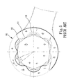
- FIGs. 5 to 8 illustrate prior art rotary wrenching tools (in the form of ring spanners for illustrative purpose) having dual nominal sizes marked thereon and constructed according to the teaching of the above-mentioned U.S. Patent Nos. 5,219,392 and 5,388,486 for wrenching fastener heads of different nominal size systems (e.g., the metric system and the inch system). Table 1 shows differences between the two nominal sizes marked thereon.
- the dual nominal size spanner so constructed for both nominal sizes of different nominal size systems has an unavoidable free rotational angle.
- a prior art rotary wrenching tool includes a head 90 having an opening (no labeled) with a number of concave sections 92 and 93 defined therein, wherein each two adjacent sections 92 and 93 are connected via a convex section 91 which bears against a face of a fastener head (not labeled) to be loosened or tightened.
- the wrenching tool must be rotated through a relatively large free rotational angle before the convex sections 91 (which are relatively small) bear against the faces of the fastener head.
- the prior art rotary wrenching tool in Fig. 5 has a difference of 0.05 mm between two nominal sizes of different nominal size systems marked thereon, wherein a maximum free rotational angle thereof is seventeen (17) degrees for a small size fastener head or eighteen (18) degrees for a large size fastener head.
- the wrenching tool is a socket wrench with, e.g., 72 teeth
- Fig. 6 shows a prior art rotary wrenching tool which has a difference of 0.1 mm between two nominal sizes of different nominal size systems marked thereon, wherein a maximum free rotational angle thereof is eighteen (18) degrees for a small size fastener head or 22.6 degrees for a large size fastener head.
- Fig. 7 shows a prior art rotary wrenching tool which has a difference of 0.3 mm between two nominal sizes of different nominal size systems marked thereon, wherein a maximum free rotational angle thereof is eighteen (18) degrees for a small size fastener head or 27.6 degrees for a large size fastener head.
- Fig. 6 shows a prior art rotary wrenching tool which has a difference of 0.1 mm between two nominal sizes of different nominal size systems marked thereon, wherein a maximum free rotational angle thereof is eighteen (18) degrees for a small size fastener head or 22.6 degrees for a large size fastener head.
- Fig. 7 shows a prior art rotary wrenching tool which has
- FIG. 8 shows a prior art rotary wrenching tool which has a difference of 0.5 mm between two nominal sizes of different nominal size systems marked thereon, wherein a maximum free rotational angle thereof is eighteen (18) degrees for a small size fastener head or thirty-nine (39) degrees for a large size fastener head. If the wrenching tool is a socket wrench, further free rotational angle is required as mentioned in the above paragraph. Consequently, the prior art wrenching tool is inconvenient to use and sometimes even inoperable when in a limited space.
- the rotary wrenching tool is illustrated as a ring spanner It is, nevertheless, appreciated that the rotary wrenching tool can be of any other form, e.g., a socket wrench or the like.
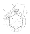
- the ring spanner designated by reference numeral "100" includes a handle 10 and a head 20 having an opening (not labeled) defined therein for receiving a polygonal head of a fastener 30 (e.g., of an inch nominal size system) or fastener 40 (e.g., of a metric nominal size system).
- An inner periphery (not labeled) defining the opening includes a number of annularly spaced grooves 21, 23 defined therein, wherein each two adjacent grooves 21 and 23 is connected by a connecting section 22.
- Each connecting section 22 includes a first operative section 213 having an end connected to one of the two adjacent grooves (e.g., groove 21) and forming a side of the groove 21, a second operative section 231 having an end connected to the other of the two adjacent grooves (groove 23) and forming a side of the groove 23, and an inoperative section 22 connected between the first operative section 213 and the second operative section 231.
- the groove 21 includes a mediate section 212 which does not contact with the fastener 30, 40 and two sides (i.e., operative sections) 211 and 213 which contact with the fastener 30, 40, while the groove 23 includes a mediate section 232 which does not contact with the fastener 30, 40 and two sides (i.e., operative sections) 211 and 213 which contact with the fastener 30, 40.
- Each inoperative section 22 includes two end which terminate at points P1 and P2, respectively. More specifically, the fastener 30, 40 does not contact with the inoperative section 22 defined between the two end points P1 and P2, which is quite different from the prior art tools shown in Figs. 5 to 8 as well as any other prior art tools.
- the inoperative section 22 may be rectilinear or concave (see the phantom lines) . In operation, the faces of the fastener 30, 40 bear against the operative sections 211, 213, 231, 233, etc. In addition, the inoperative section 22, if in a convex outline, has a maximum depth greater than a diagonal length of the fastener to be wrenched.
- the ring spanner in Fig. 1 has a difference of 0.05 mm between two nominal sizes of different nominal size systems marked thereon, wherein a maximum free rotational angle thereof is four (4) degrees for both small size fastener head and large size fastener head.
- Fig. 2 shows a ring spanner in accordance with the present invention which has a difference of 0.1 mm between two nominal sizes of different nominal size systems marked thereon, wherein a maximum free rotational angle thereof is four (4) degrees for a small size fastener head or eight (8) degrees for a large size fastener head.
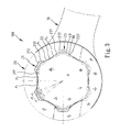
- FIG. 3 shows a ring spanner in accordance with the present invention which has a difference of 0.3 mm between two nominal sizes of different nominal size systems marked thereon, wherein a maximum free rotational angle thereof is eight (8) degrees for a small size fastener head or sixteen (16) degrees for a large size fastener head.
- Fig. 4 shows a ring spanner in accordance with the present invention which has a difference of 0.5 mm between two nominal sizes of different nominal size systems marked thereon, wherein a maximum free rotational angle thereof is fourteen (14) degrees for a small size fastener head or thirty (30) degrees for a large size fastener head. If the wrenching tool is a socket wrench, further free rotational angle is required as mentioned above. Referring to Figs.
- the grooves 21, 23 of a spanner with a smaller nominal size difference e.g, of 0.05 mm, see Fig. 1
- the grooves 21, 23 of a spanner with a larger nominal size difference e.g., of 0.5 mm, see Fig. 4
- the dual nominal size spanners constructed in accordance with the present invention have relatively smaller free rotational angles when compared with those of prior art dual nominal size spanners.
- the spanners in accordance with the present invention are advantageous when used in limited spaces.
Landscapes
- Engineering & Computer Science (AREA)
- Mechanical Engineering (AREA)
- Details Of Spanners, Wrenches, And Screw Drivers And Accessories (AREA)
- Slide Fasteners (AREA)
Priority Applications (6)
| Application Number | Priority Date | Filing Date | Title |
|---|---|---|---|
| CA002234179A CA2234179C (en) | 1998-04-07 | 1998-04-07 | Rotary wrenching tool |
| EP98110973A EP0979708A1 (de) | 1998-04-07 | 1998-06-16 | Schraubwerkzeug |
| AU73067/98A AU7306798A (en) | 1998-04-07 | 1998-06-22 | Rotary wrenching tool |
| BR9802401-9A BR9802401A (pt) | 1998-04-07 | 1998-07-06 | Chave de porca giratória |
| JP10197393A JP2000024941A (ja) | 1998-04-07 | 1998-07-13 | 二種類の単位のねじに適用することのできる工具 |
| US09/734,932 US20020104409A1 (en) | 1998-04-07 | 2000-12-11 | Rotary wrenching tool |
Applications Claiming Priority (6)
| Application Number | Priority Date | Filing Date | Title |
|---|---|---|---|
| CA002234179A CA2234179C (en) | 1998-04-07 | 1998-04-07 | Rotary wrenching tool |
| EP98110973A EP0979708A1 (de) | 1998-04-07 | 1998-06-16 | Schraubwerkzeug |
| AU73067/98A AU7306798A (en) | 1998-04-07 | 1998-06-22 | Rotary wrenching tool |
| BR9802401-9A BR9802401A (pt) | 1998-04-07 | 1998-07-06 | Chave de porca giratória |
| JP10197393A JP2000024941A (ja) | 1998-04-07 | 1998-07-13 | 二種類の単位のねじに適用することのできる工具 |
| US09/734,932 US20020104409A1 (en) | 1998-04-07 | 2000-12-11 | Rotary wrenching tool |
Publications (1)
| Publication Number | Publication Date |
|---|---|
| EP0979708A1 true EP0979708A1 (de) | 2000-02-16 |
Family
ID=33437261
Family Applications (1)
| Application Number | Title | Priority Date | Filing Date |
|---|---|---|---|
| EP98110973A Withdrawn EP0979708A1 (de) | 1998-04-07 | 1998-06-16 | Schraubwerkzeug |
Country Status (6)
| Country | Link |
|---|---|
| US (1) | US20020104409A1 (de) |
| EP (1) | EP0979708A1 (de) |
| JP (1) | JP2000024941A (de) |
| AU (1) | AU7306798A (de) |
| BR (1) | BR9802401A (de) |
| CA (1) | CA2234179C (de) |
Cited By (1)
| Publication number | Priority date | Publication date | Assignee | Title |
|---|---|---|---|---|
| AT10777U3 (de) * | 2008-10-06 | 2010-05-15 | Iws Fertigungstechnik Gmbh | Steckschlüsseleinsatz |
Families Citing this family (8)
| Publication number | Priority date | Publication date | Assignee | Title |
|---|---|---|---|---|
| GB0303007D0 (en) * | 2003-02-10 | 2003-03-12 | Smart Tools Ltd | Wrench socket |
| US20060130618A1 (en) * | 2004-12-21 | 2006-06-22 | Chih-Ching Hsieh | Sleeve with adaptable hole |
| GB0814013D0 (en) * | 2008-07-31 | 2008-09-10 | Smart Tools Ltd | Wrench socket |
| TWM398998U (en) * | 2010-08-13 | 2011-03-01 | Xi-Gang Xu | Quick coupling sleeve with guiding feature |
| US11806843B2 (en) | 2013-11-15 | 2023-11-07 | Snap-On Incorporated | Socket drive improvement |
| US9718170B2 (en) | 2013-11-15 | 2017-08-01 | Snap-On Incorporated | Socket drive improvement |
| EP3424646A1 (de) * | 2017-07-05 | 2019-01-09 | HILTI Aktiengesellschaft | Setzwerkzeug, set für ein setzwerkzeugsystem und setzwerkzeugsystem |
| US20250269504A1 (en) * | 2024-02-26 | 2025-08-28 | Yu-Ping Tsai | Engaging structure for hand tool |
Citations (4)
| Publication number | Priority date | Publication date | Assignee | Title |
|---|---|---|---|---|
| US4581957A (en) * | 1984-02-24 | 1986-04-15 | Facom | Tightening tool for nuts or bolts |
| US4598616A (en) * | 1985-09-18 | 1986-07-08 | Colvin David S | Wrench opening |
| US4646594A (en) * | 1984-08-08 | 1987-03-03 | Tien Kuang Yung | Wrench socket |
| US4930378A (en) * | 1988-04-22 | 1990-06-05 | David S. Colvin | Wrench opening engagement surface configuration |
-
1998
- 1998-04-07 CA CA002234179A patent/CA2234179C/en not_active Expired - Fee Related
- 1998-06-16 EP EP98110973A patent/EP0979708A1/de not_active Withdrawn
- 1998-06-22 AU AU73067/98A patent/AU7306798A/en not_active Abandoned
- 1998-07-06 BR BR9802401-9A patent/BR9802401A/pt active Search and Examination
- 1998-07-13 JP JP10197393A patent/JP2000024941A/ja active Pending
-
2000
- 2000-12-11 US US09/734,932 patent/US20020104409A1/en not_active Abandoned
Patent Citations (4)
| Publication number | Priority date | Publication date | Assignee | Title |
|---|---|---|---|---|
| US4581957A (en) * | 1984-02-24 | 1986-04-15 | Facom | Tightening tool for nuts or bolts |
| US4646594A (en) * | 1984-08-08 | 1987-03-03 | Tien Kuang Yung | Wrench socket |
| US4598616A (en) * | 1985-09-18 | 1986-07-08 | Colvin David S | Wrench opening |
| US4930378A (en) * | 1988-04-22 | 1990-06-05 | David S. Colvin | Wrench opening engagement surface configuration |
Cited By (1)
| Publication number | Priority date | Publication date | Assignee | Title |
|---|---|---|---|---|
| AT10777U3 (de) * | 2008-10-06 | 2010-05-15 | Iws Fertigungstechnik Gmbh | Steckschlüsseleinsatz |
Also Published As
| Publication number | Publication date |
|---|---|
| CA2234179A1 (en) | 1999-10-07 |
| CA2234179C (en) | 2001-05-15 |
| BR9802401A (pt) | 2001-07-03 |
| AU7306798A (en) | 2000-01-06 |
| JP2000024941A (ja) | 2000-01-25 |
| US20020104409A1 (en) | 2002-08-08 |
Similar Documents
| Publication | Publication Date | Title |
|---|---|---|
| US5219392A (en) | Rotary wrenching tool | |
| TWI773735B (zh) | 多向驅動頭 | |
| CN113770963B (zh) | 多夹持点套筒起子头 | |
| JP2958858B2 (ja) | 整合締め付け用スクリュ及びスパナ | |
| US6301998B1 (en) | Ratchet wheel with asymmetric arcuate concave teeth or non-arcuate concave teeth and socket wrench with such ratchet wheel | |
| US5492040A (en) | Dual wrench and method therefor | |
| US6357323B2 (en) | Wrench | |
| US20220281085A1 (en) | Multi-Directional Driver Bit | |
| US6745647B2 (en) | Wrench having a universal-joint ratchet wheel | |
| EP0979708A1 (de) | Schraubwerkzeug | |
| US20070214915A1 (en) | Fitting hole of a hand tool | |
| US6938524B2 (en) | Engaging recess for sockets | |
| CN115122248B (zh) | 轴向钳 | |
| EP0525356B1 (de) | Schraubenschlüssel | |
| US20020078800A1 (en) | Socket wrench extension with improved torque transmission | |
| GB2275637A (en) | Improvements in and relating to wrench and socket systems | |
| US12263561B2 (en) | Ratchet wrench | |
| US20040221688A1 (en) | Socket for a wrench | |
| US20040025642A1 (en) | Ratchet pipe wrench | |
| US20240217072A1 (en) | Ratchet ring | |
| TWI807482B (zh) | 多夾持點套筒起子頭 | |
| US20040060398A1 (en) | Hand tool having pivotable function end | |
| WO2023230168A1 (en) | Multi-directional driver bit | |
| JP4436016B2 (ja) | ボルト・ナットの共回り防止治具 | |
| US6666113B1 (en) | Valve wrench |
Legal Events
| Date | Code | Title | Description |
|---|---|---|---|
| PUAI | Public reference made under article 153(3) epc to a published international application that has entered the european phase |
Free format text: ORIGINAL CODE: 0009012 |
|
| 17P | Request for examination filed |
Effective date: 19981120 |
|
| AK | Designated contracting states |
Kind code of ref document: A1 Designated state(s): DE ES FR GB IT NL |
|
| AX | Request for extension of the european patent |
Free format text: AL;LT;LV;MK;RO;SI |
|
| AKX | Designation fees paid |
Free format text: DE ES FR GB IT NL |
|
| 17Q | First examination report despatched |
Effective date: 20010828 |
|
| STAA | Information on the status of an ep patent application or granted ep patent |
Free format text: STATUS: THE APPLICATION IS DEEMED TO BE WITHDRAWN |
|
| 18D | Application deemed to be withdrawn |
Effective date: 20020718 |