EP0979757A2 - Rückspiegel - Google Patents
Rückspiegel Download PDFInfo
- Publication number
- EP0979757A2 EP0979757A2 EP99306132A EP99306132A EP0979757A2 EP 0979757 A2 EP0979757 A2 EP 0979757A2 EP 99306132 A EP99306132 A EP 99306132A EP 99306132 A EP99306132 A EP 99306132A EP 0979757 A2 EP0979757 A2 EP 0979757A2
- Authority
- EP
- European Patent Office
- Prior art keywords
- reflective member
- case
- shaft
- rear view
- mirror assembly
- Prior art date
- Legal status (The legal status is an assumption and is not a legal conclusion. Google has not performed a legal analysis and makes no representation as to the accuracy of the status listed.)
- Granted
Links
- 230000015572 biosynthetic process Effects 0.000 claims abstract description 6
- 230000002093 peripheral effect Effects 0.000 claims description 15
- 230000000694 effects Effects 0.000 claims description 2
- 238000000926 separation method Methods 0.000 claims description 2
- 238000006073 displacement reaction Methods 0.000 claims 2
- 238000005755 formation reaction Methods 0.000 abstract description 5
- 230000000712 assembly Effects 0.000 description 3
- 238000000429 assembly Methods 0.000 description 3
- 239000011521 glass Substances 0.000 description 3
- 238000006243 chemical reaction Methods 0.000 description 1
- 230000008676 import Effects 0.000 description 1
Images


Classifications
-
- B—PERFORMING OPERATIONS; TRANSPORTING
- B60—VEHICLES IN GENERAL
- B60R—VEHICLES, VEHICLE FITTINGS, OR VEHICLE PARTS, NOT OTHERWISE PROVIDED FOR
- B60R1/00—Optical viewing arrangements; Real-time viewing arrangements for drivers or passengers using optical image capturing systems, e.g. cameras or video systems specially adapted for use in or on vehicles
- B60R1/02—Rear-view mirror arrangements
- B60R1/06—Rear-view mirror arrangements mounted on vehicle exterior
- B60R1/062—Rear-view mirror arrangements mounted on vehicle exterior with remote control for adjusting position
- B60R1/07—Rear-view mirror arrangements mounted on vehicle exterior with remote control for adjusting position by electrically powered actuators
- B60R1/072—Rear-view mirror arrangements mounted on vehicle exterior with remote control for adjusting position by electrically powered actuators for adjusting the mirror relative to its housing
-
- Y—GENERAL TAGGING OF NEW TECHNOLOGICAL DEVELOPMENTS; GENERAL TAGGING OF CROSS-SECTIONAL TECHNOLOGIES SPANNING OVER SEVERAL SECTIONS OF THE IPC; TECHNICAL SUBJECTS COVERED BY FORMER USPC CROSS-REFERENCE ART COLLECTIONS [XRACs] AND DIGESTS
- Y10—TECHNICAL SUBJECTS COVERED BY FORMER USPC
- Y10S—TECHNICAL SUBJECTS COVERED BY FORMER USPC CROSS-REFERENCE ART COLLECTIONS [XRACs] AND DIGESTS
- Y10S248/00—Supports
- Y10S248/90—Movable or disengageable on impact or overload
Definitions
- This invention relates to a rear view mirror assembly having an attaching portion for attaching said mirror assembly externally of a vehicle, a mirror case extending outwardly from said attaching portion, a reflective member having a surface plane and an outer periphery that includes a side peripheral portion, said reflective member being mounted in said case for angular adjustment relative to said case and with said side peripheral portion located adjacent said attaching portion for movement in an arcuate path during angular adjustment of said reflective member and a drive unit being arranged to effect angular movement of the reflective member relative to the case.
- the invention is applicable both to rear view mirror assemblies of the type in which the case is rigidly mounted on the bracket and to mirror assemblies of the type in which the case is pivotally mounted on the bracket so as to be displaceable from its position of normal use, for example when subject to impact, for example as described in EP-A-0392721.
- EP-A-0272047 discloses a mirror of this type in which two electric motors are mounted behind the reflective member and coupled thereto by respective screw jack drives.
- EP-A-0860323 discloses a similar mechanism in which a single motor and screw jack drive is used to vary the angular position of a reflective member about a single axis. In both cases, the motor or motors and their associated drives make a significant contribution to the weight of the mirror case and therefore increase the extent to which the mirror assembly is liable to vibrate. It is an object of the present invention to provide a mirror assembly of the type described above in which at least part of the drive mechanism is located in the mirror bracket so as to be closer to the location at which the mirror assembly is mounted on the vehicle body.
- the drive unit in a mirror assembly of the type described above, includes a rotatable shaft mounted in said attaching portion and having a longitudinal axis extending generally in the direction of said arcuate path, said reflective member includes a follower extending outwardly therefrom beyond said side peripheral portion into engagement with said shaft, and said shaft and said follower are co-operably shaped to convert rotary motion of said shaft into motion of said follower along said shaft to impart angular movement to said reflective member.
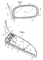
- a rear view mirror has a case 10 mounted on a bracket 12 which has an inner face 14 adapted to abut a motor vehicle body (not shown).
- the case 10 is connected to the bracket 12 by a mechanism allowing relative angular movement in the fore and aft direction, as described in EP-A-0392721, the disclosure of which is hereby incorporated herein by reference.
- a reflective member 16 for example silvered glass, is mounted on a mirror carrier 18, which is coupled to a support member 24 within the case 10 by hinges 20 and 22, both of which are shown in Figure 4 while only hinge 20 is visible in Figures 2, 5, 9 and 10.
- the hinges 20 and 22 allow angular movement of the mirror carrier 18 about an inclined axis 25 shown in Figure 4, the orientation of which is determined in the manner described in EP-A-0860323.
- An electric motor 26 is mounted within the bracket 12 and has its output shaft coupled by a reduction gear 28 to a lead screw 30 which is mounted with its axis lying in the plane of separation between the case 10 and the bracket 12 when the former is pivoted forwardly or rearwardly, as described above.
- the mirror carrier 18 has a pair of mutually parallel arms 32 and 34 projecting rearwardly and laterally so that their ends embrace the lead screw 30 and are urged into contact therewith by a U-shaped spring 36.
- the confronting faces of ends of the arms 32 and 34 have grooved regions 38 and 40 of the same pitch as the lead screw 30. Consequently, when the lead screw 30 is rotated by the motor 26, the arms 32 and 34 are displaced longitudinally along the lead screw 30, causing the mirror carrier 18 to pivot about the axis 25 of the hinges 20 and 22 shown in Figure 4.
- the lead screw thread is of fine pitch and open angle form (for example 0.5mm pitch and 45° flank angle) .
- the grooved regions 38 and 40 of the arms 32 and 34 can jump over the thread of the lead screw 30 against the action of the spring 34, thereby avoiding damage to the mechanism and allowing manual adjustment of the reflective member 16 in the event of motor drive failure.
- the case 10 When the case 10 is subject to a force tending to displace it from its normal position, shown in Figure 2, towards the rear of the vehicle, it pivots to the position shown in Figure 5.
- the arms 32 and 34 have disengaged from the lead screw 30 and are urged into engagement with a stop bar 42 (see Figures 3 and 6) on the case 10 which extends parallel and adjacent to the lead screw 30 when the case 10 is in its normal position.
- the stop bar 42 has grooved formations of the same pitch as the lead screw on its surfaces facing the grooved regions 38 and 40 of the arms 32 and 34.
- Figure 7 shows the case 10 displaced forwardly from its normal position.
- the arms 32 and 34 disengage from the lead screw 30, and re-engage therewith when the case 10 is restored to its normal position, in the same manner as described with reference to Figures 5 and 6.
- Figure 8 shows the mirror assembly with the case 10 in its normal position and the mirror carrier 18 driven by the lead screw 30 to its maximum outwardly directed orientation.
- Figure 9 shows the mirror carrier 18 displaced to its maximum inward facing orientation.
- Figure 10 shows a second embodiment of the invention in which the separate mirror case 10 and bracket 12 are replaced by a single combined case 50 which is rigidly fixed to the vehicle body. Since there is no displaceable case, the arms 32 and 34 do not disengage from the lead screw 30. Consequently, there is no stop bar equivalent to the stop bar 42 of the first embodiment. Otherwise, the mechanism is as described with reference to Figures 1 to 4, corresponding parts being denoted by the same reference numerals.
- Figures 11 to 14 show another rear view mirror having a case 60 mounted on a bracket 62 which has an inner face 64 adapted to abut a motor vehicle body (not shown).
- the case 60 is connected to the bracket 62 by a mechanism allowing relative angular movement in the fore and aft direction.
- a reflective member 66 is mounted on a mirror carrier 68 which differs from the mirror carrier of Figures 1 to 4 in that it is coupled by a ball and socket joint 70 to a support member 72 so as to allow angular movement of the mirror carrier 68 about both vertical and horizontal axes that may be referred to as first and second orthogonal axes.
- two electric motors 74 and 76 are mounted within the bracket 62, each having its output shaft coupled by a respective reduction gear 78, 80 to a respective upper and lower lead screw 82, 84.
- the mirror carrier 68 has an upper pair of mutually parallel arms 86, 88 and a lower pair of mutually parallel arms 90, 92 similar to the arms 32 and 34 shown in Figure 3.
- the upper pair of arms 86, 88 have grooved regions for engagement with the upper lead screw 82 while the lower pair of arms has grooved regions for engagement with the lower lead screw 84.
- Each pair of arms has a respective U-shaped spring 96 for urging the ends of the arms into engagement with the respective lead screws 82 and 84.
- Each of the lead screws operates in a similar manner to that described with reference to Figures 8 and 9. Rotation of both lead screws 82 and 84 in the same direction causes adjustment of the orientation of the mirror carrier 68 about a generally vertical axis. Rotation of the two lead screws 82 and 84 in opposite directions to one another causes variation in the orientation of the mirror carrier 68 about a generally horizontal axis.
- the case 60 has a pair of stop bars, one of which is visible at 98 in Figure 12 which engage between the respective pairs of arms 86, 88 and 90, 92 when the case 60 is displaced forwardly or rearwardly in a similar manner to that described with reference to Figures 5 to 7.
- the vertical thickness of these stop bars is substantially less than the diameter of the lead screws 82 and 84 so as to avoid any risk of the grooved formations thereon coming into engagement with the grooved regions 38 and 40 of the arms 88-92 during adjustment of the orientation of the mirror carrier 68 about said generally horizontal axis.
- mirror carrier 18 has an outer periphery that includes top and bottom peripheral portions 120, 122, and opposite side peripheral portions 124, 126. These peripheral portions of carrier 18 also define corresponding peripheral portions of reflective member 16. In the embodiment of Figures 11-14, these peripheral portions of reflective member 66 and its carrier 68 are identified by numerals 220, 222, 224 and 226. In the embodiment of Figures 11-14, reflective member 66 and its carrier 68 are capable of angular movement about both vertical and horizontal axes that are illustrated at 230, 232 in Figure 13, and may be referred to as first and second orthogonal axes.
- vertical axis 25 may be vertical, inclined within a vertical plane, and/or inclined out of a vertical plane.
- one way of determining a desirable angle of inclination for axis 25 is explained in EP-A-9272047. However, it will be recognised that other ways of determining a desirable angle can be used.
- Reflective member 16 and its carrier 18 rotate clockwise and counterclockwise about axis 25.
- the midpoint position of movement is illustrated in Figures 2 and 10, while the clockwise end limit position of movement is illustrated in Figure 9.
- the opposite or counterclockwise end limit position of movement is counterclockwise from the midpoint position of Figures 2 and 10, and the end portions of arms 32, 34 would be located adjacent the opposite end portion of lead screw 30 as compared to the clockwise end limit position of Figure 9.
- side peripheral portion 124 of reflective member 16 and its carrier 18 travel in an arcuate path adjacent to bracket or attaching portion 12.
- the arcuate path is around 20° which is around 10° in each of opposite directions from the midpoint position of Figures 2 and 10.
- the arcuate path could extend anywhere from 10° to 40° which would be between 5° and 20° in each of opposite directions from the midpoint position of Figures 2 and 10.
- a given point on side peripheral portion 124 may travel in an arcuate path that is within a horizontal plane or is inclined relative to a horizontal plane.
- Lead screw 30 extends in the general direction of movement of side peripheral portion 124 or in the general direction of the arcuate path.
- the arcuate path is closest to the screw in the midpoint position of the mirror and is further away from the screw in the end limit positions of the mirror.
- the axis of the lead screw is usually parallel to a line that is tangent to the arcuate path through which the given point travels.
- the longitudinal axis of lead screw 30 usually would be inclined at an included angle with the plane of bracket inner face 14 of 25° to 45° and more preferably 30° to 40°. In the arrangement shown, the angle is about 35°.
- Lead screw 30 may also be horizontal or inclined above or below a horizontal plane. When inclined to the horizontal the angle of inclination is within 20° in each of opposite directions from the horizontal and more preferably within 10° either above or below the horizontal.
- Reflective member or mirror 16 is shown as having a curved outer surface at a very large radius but it could be flat. With the curvature flattened or removed, the mirror outer surface has a surface plane. Therefore, references to the mirror as having a surface plane does not necessarily mean that the mirror surface is flat or plane.
- the longitudinal axis of lead screw 30 could extend perpendicular to the mirror plane or could be inclined relative thereto.
- the angle of inclination preferably is not greater than 35° in horizontal or vertical planes.
- the axis of lead screw 30 could be inclined up to 35° in a horizontal plane in either of opposite directions from a line that is perpendicular to the mirror plane, and could be inclined up to 35° in a horizontal plane in either of opposite directions from a line that is perpendicular to the mirror plane, and could be inclined up to 35° in a vertical plane in either of opposite directions from a line that is perpendicular to the mirror plane.
- the projected length of the lead screw that extends perpendicular to the mirror plane is equal to the length of the lead screw times the cosine of the angle between 0° and 35°.
- the cosine of 35° is 0.81915 so that approximately 82% of the length of the lead screw extends in a direction perpendicular to the mirror plane when the lead screw is inclined at 35°.
- the length of the lead screw may be resolved into components that extend both parallel and perpendicular to the mirror plane in the midpoint position of the mirror.
- the parallel component is equal to the lead screw length times the sine of the inclination angle, and the perpendicular component is between 80% and 100% of the total lead screw length.
- the position, inclination or lack of inclination of the lead screw with respect to the mirror also may be considered with respect to the directional components.
- the directional component of the axis that is perpendicular to the mirror plane is 100%.
- the longitudinal axis of the screw is inclined to the surface plane of the mirror in its midpoint position in a direction that forms an included angle of 35° with a line that is perpendicular to the surface plane of the mirror, the directional component that is perpendicular to the mirror plane is equal to the cosine of 35° or about 82%.
- the longitudinal axis of the lead screw is oriented in a direction such that its directional component that is perpendicular to the mirror plane is between 80 and 100% or greater than 80%.
- the principal directional component of the direction in which the shaft extends is one that extends perpendicular to the surface plane of the mirror. This principal directional component is at least 80% of the direction that is resolvable into components extending both parallel and perpendicular to the surface plane of the mirror.
- Lead screw or worm gear 30 may be considered an elongated rotatable shaft that co-operates with followers define by arms 32, 34 to convert rotary motion of the shaft to motion of the arms linearly along the shaft.
- Other motion conversion arrangements are possible such as a smooth shaft co-operable with skewed rollers attached to the follower arms, or a grooved shaft co-operable with small balls attached to the follower arms.
- the rollers or balls would be on a part to which the arms are attached to import swinging motion of the arms as the part moves along the shaft while permitting relative movement between the part and the arms in a direction transversely of the shaft longitudinal axis.
Landscapes
- Engineering & Computer Science (AREA)
- Multimedia (AREA)
- Mechanical Engineering (AREA)
- Rear-View Mirror Devices That Are Mounted On The Exterior Of The Vehicle (AREA)
Applications Claiming Priority (3)
| Application Number | Priority Date | Filing Date | Title |
|---|---|---|---|
| GB9817205 | 1998-08-08 | ||
| GBGB9817205.9A GB9817205D0 (en) | 1998-08-08 | 1998-08-08 | Rear view mirror |
| US09/366,109 US6106122A (en) | 1998-08-08 | 1999-08-02 | Rear view mirror |
Publications (3)
| Publication Number | Publication Date |
|---|---|
| EP0979757A2 true EP0979757A2 (de) | 2000-02-16 |
| EP0979757A3 EP0979757A3 (de) | 2001-01-17 |
| EP0979757B1 EP0979757B1 (de) | 2004-06-09 |
Family
ID=26314180
Family Applications (1)
| Application Number | Title | Priority Date | Filing Date |
|---|---|---|---|
| EP99306132A Expired - Lifetime EP0979757B1 (de) | 1998-08-08 | 1999-08-02 | Rückspiegel |
Country Status (6)
| Country | Link |
|---|---|
| US (1) | US6106122A (de) |
| EP (1) | EP0979757B1 (de) |
| JP (1) | JP4225637B2 (de) |
| CN (1) | CN1245761A (de) |
| BR (1) | BR9903563A (de) |
| GB (1) | GB9817205D0 (de) |
Cited By (1)
| Publication number | Priority date | Publication date | Assignee | Title |
|---|---|---|---|---|
| WO2004009407A3 (en) * | 2002-07-19 | 2004-10-28 | Magna Donnelly North America L | Mounting system for vehicule mirror |
Families Citing this family (10)
| Publication number | Priority date | Publication date | Assignee | Title |
|---|---|---|---|---|
| DE60004830T2 (de) * | 1999-06-24 | 2004-06-17 | Magna Mirror Systems Inc., Alto | Modularer, verlängerbarer spiegel |
| DE102005021757A1 (de) * | 2005-05-11 | 2006-11-16 | Schefenacker Vision Systems Germany Gmbh | Aussenrückblickspiegel für Fahrzeuge, vorzugsweise für Kraftfahrzeuge |
| TWD134956S1 (zh) * | 2009-02-03 | 2010-05-21 | Bmw股份有限公司 | 汽車 |
| CN103782095A (zh) * | 2011-09-08 | 2014-05-07 | 格莱特有限公司 | 可旋转光学装置壳体以及安装平台 |
| US9796334B2 (en) | 2014-06-13 | 2017-10-24 | Magna Mirrors Of America, Inc. | Exterior rearview mirror assembly for vehicle |
| US11639039B1 (en) | 2016-02-04 | 2023-05-02 | Maurice Paperi | Matching pieces and kits for repairing broken structures and related methods |
| CN107351768B (zh) * | 2017-07-20 | 2019-08-23 | 王雁飞 | 一种用于防撞的后视镜 |
| US11148578B2 (en) * | 2018-03-25 | 2021-10-19 | Maurice Paperi | Universal mounting tabs and kits for automotive components |
| US12246648B2 (en) | 2021-01-19 | 2025-03-11 | Magna Mirrors Of America, Inc. | Vehicular exterior rearview mirror assembly with locking feature |
| US12351108B2 (en) | 2021-07-09 | 2025-07-08 | Magna Mirrors Of America, Inc. | Vehicular exterior rearview mirror assembly with extendable and retractable mirror head |
Citations (3)
| Publication number | Priority date | Publication date | Assignee | Title |
|---|---|---|---|---|
| EP0272047A2 (de) | 1986-12-12 | 1988-06-22 | Britax Rainsfords Pty. Ltd. | Schwenkbarer Spindeltrieb |
| EP0392721A2 (de) | 1989-04-13 | 1990-10-17 | Britax (Geco) S.A. | Aussenrückblickspiegel für ein Kraftfahrzeug |
| EP0860323A2 (de) | 1997-02-19 | 1998-08-26 | Britax (Geco) S.A. | Fahrzeugaussenrückblickspiegel |
Family Cites Families (13)
| Publication number | Priority date | Publication date | Assignee | Title |
|---|---|---|---|---|
| US3628862A (en) * | 1969-08-25 | 1971-12-21 | Allied Chem | Power actuated rearview mirror |
| DE2642117A1 (de) * | 1976-09-18 | 1978-03-23 | Maerklin & Cie Gmbh Geb | Triebwerk fuer die zwei umsteuerbaren elektromotoren einer schwenkbaren spiegelscheibe |
| DE2952084C2 (de) * | 1979-12-22 | 1985-10-10 | Kienzle Uhrenfabriken GmbH, 7730 Villingen-Schwenningen | Elektrisch mit mindestens einem Elektromotor betätigbare Verstellvorrichtung für Kraftfahrzeugrückblickspiegel |
| DE3204791C1 (de) * | 1982-02-11 | 1983-10-06 | Daimler Benz Ag | Servomotorisch einstellbarer Aussenspiegel fuer Fahrzeuge |
| DE3440477A1 (de) * | 1984-11-06 | 1986-05-22 | Hagus C. Luchtenberg Gmbh & Co Kg, 5650 Solingen | Aussenspiegel fuer fahrzeuge |
| JPH0355464Y2 (de) * | 1984-11-06 | 1991-12-10 | ||
| JPH07110597B2 (ja) * | 1987-02-10 | 1995-11-29 | 株式会社小糸製作所 | 電動格納型ドアミラ− |
| DE3713579A1 (de) * | 1987-04-23 | 1988-11-03 | Bernhard Mittelhaeuser | Aussenrueckblickspiegel fuer kraftfahrzeuge |
| DE3800171A1 (de) * | 1988-01-07 | 1989-07-20 | Bernhard Mittelhaeuser | Kraftfahrzeugrueckblickspiegel |
| DE3819471A1 (de) * | 1988-06-08 | 1989-12-14 | Daimler Benz Ag | Aussenspiegel fuer fahrzeuge |
| DE3926892C2 (de) * | 1989-08-16 | 1997-12-18 | Bernhard Mittelhaeuser | Aussenrückblickspiegel für Kraftfahrzeuge |
| JPH04136949U (ja) * | 1991-06-17 | 1992-12-21 | 株式会社村上開明堂 | 可倒式ドアミラー |
| US5477390A (en) * | 1993-08-16 | 1995-12-19 | Lowell Engineering Corp. | Mirror assembly powered into rearwardly folded position against reversing spring bias |
-
1998
- 1998-08-08 GB GBGB9817205.9A patent/GB9817205D0/en not_active Ceased
-
1999
- 1999-07-16 JP JP20313299A patent/JP4225637B2/ja not_active Expired - Fee Related
- 1999-08-02 US US09/366,109 patent/US6106122A/en not_active Expired - Fee Related
- 1999-08-02 EP EP99306132A patent/EP0979757B1/de not_active Expired - Lifetime
- 1999-08-06 BR BR9903563-4A patent/BR9903563A/pt not_active Application Discontinuation
- 1999-08-06 CN CN99117607.3A patent/CN1245761A/zh active Pending
Patent Citations (3)
| Publication number | Priority date | Publication date | Assignee | Title |
|---|---|---|---|---|
| EP0272047A2 (de) | 1986-12-12 | 1988-06-22 | Britax Rainsfords Pty. Ltd. | Schwenkbarer Spindeltrieb |
| EP0392721A2 (de) | 1989-04-13 | 1990-10-17 | Britax (Geco) S.A. | Aussenrückblickspiegel für ein Kraftfahrzeug |
| EP0860323A2 (de) | 1997-02-19 | 1998-08-26 | Britax (Geco) S.A. | Fahrzeugaussenrückblickspiegel |
Cited By (2)
| Publication number | Priority date | Publication date | Assignee | Title |
|---|---|---|---|---|
| WO2004009407A3 (en) * | 2002-07-19 | 2004-10-28 | Magna Donnelly North America L | Mounting system for vehicule mirror |
| US7726624B2 (en) | 2002-07-19 | 2010-06-01 | Magna Mirrors Of America, Inc. | Mounting system for vehicular mirror |
Also Published As
| Publication number | Publication date |
|---|---|
| EP0979757B1 (de) | 2004-06-09 |
| JP2000052863A (ja) | 2000-02-22 |
| US6106122A (en) | 2000-08-22 |
| BR9903563A (pt) | 2000-08-29 |
| EP0979757A3 (de) | 2001-01-17 |
| CN1245761A (zh) | 2000-03-01 |
| GB9817205D0 (en) | 1998-10-07 |
| JP4225637B2 (ja) | 2009-02-18 |
Similar Documents
| Publication | Publication Date | Title |
|---|---|---|
| EP0979757B1 (de) | Rückspiegel | |
| US8366560B2 (en) | Coupling device for coupling a rotating shaft and a rotating member, and rotating device using the same | |
| US6959900B2 (en) | Powered sliding apparatus for a seat | |
| US20200180167A1 (en) | Robot and arm assembly thereof | |
| JP3320841B2 (ja) | 織機に使用されるカム機構 | |
| US20030168566A1 (en) | Power sliding apparatus for a seat | |
| US6916064B2 (en) | Sliding roof system for a motor vehicle | |
| JP7703374B2 (ja) | 車両用アウトサイドミラー装置における鏡面角度調整ユニット、車両用アウトサイドミラー装置 | |
| JP5201393B2 (ja) | ヒンジ構造と自動車外部のミラーユニット | |
| CN102427972A (zh) | 车窗刮水器设备 | |
| US6164148A (en) | Motorized actuator for vehicle wing mirrors | |
| EP0566060B1 (de) | Fahrzeugfensterhebervorrichtung | |
| KR102213288B1 (ko) | 자동차의 스태빌라이저 | |
| CN116575802B (zh) | 一种门窗传动壳及门窗结构 | |
| JP7703375B2 (ja) | 車両用アウトサイドミラー装置における鏡面角度調整ユニット、車両用アウトサイドミラー装置 | |
| KR20000017137A (ko) | 백미러 | |
| JPH0356421Y2 (de) | ||
| CA2259815C (en) | Self aligning drive nut bracket | |
| CN1786357B (zh) | 电动式操作装置 | |
| JP3925270B2 (ja) | モータ駆動装置 | |
| KR102878163B1 (ko) | 전동 사이드스텝 링크 어셈블리 | |
| JP2005030448A (ja) | 伝動機構及びパワーシートスライド装置 | |
| KR102918464B1 (ko) | 삼륜차 피벗 조인트의 스윙 유닛 | |
| EP3904628B1 (de) | Fenster mit schubkettenaktuator | |
| US6010226A (en) | Vehicle exterior mirror |
Legal Events
| Date | Code | Title | Description |
|---|---|---|---|
| PUAI | Public reference made under article 153(3) epc to a published international application that has entered the european phase |
Free format text: ORIGINAL CODE: 0009012 |
|
| AK | Designated contracting states |
Kind code of ref document: A2 Designated state(s): DE FR GB |
|
| AX | Request for extension of the european patent |
Free format text: AL;LT;LV;MK;RO;SI |
|
| PUAL | Search report despatched |
Free format text: ORIGINAL CODE: 0009013 |
|
| AK | Designated contracting states |
Kind code of ref document: A3 Designated state(s): AT BE CH CY DE DK ES FI FR GB GR IE IT LI LU MC NL PT SE |
|
| AX | Request for extension of the european patent |
Free format text: AL;LT;LV;MK;RO;SI |
|
| RIC1 | Information provided on ipc code assigned before grant |
Free format text: 7B 60R 1/06 A, 7B 60R 1/072 B |
|
| 17P | Request for examination filed |
Effective date: 20010412 |
|
| AKX | Designation fees paid |
Free format text: DE FR GB |
|
| RAP1 | Party data changed (applicant data changed or rights of an application transferred) |
Owner name: SCHEFENACKER VISION SYSTEMS AUSTRALIA PTY LTD |
|
| 17Q | First examination report despatched |
Effective date: 20030303 |
|
| GRAP | Despatch of communication of intention to grant a patent |
Free format text: ORIGINAL CODE: EPIDOSNIGR1 |
|
| GRAS | Grant fee paid |
Free format text: ORIGINAL CODE: EPIDOSNIGR3 |
|
| GRAA | (expected) grant |
Free format text: ORIGINAL CODE: 0009210 |
|
| AK | Designated contracting states |
Kind code of ref document: B1 Designated state(s): DE FR GB |
|
| PG25 | Lapsed in a contracting state [announced via postgrant information from national office to epo] |
Ref country code: FR Free format text: LAPSE BECAUSE OF FAILURE TO SUBMIT A TRANSLATION OF THE DESCRIPTION OR TO PAY THE FEE WITHIN THE PRESCRIBED TIME-LIMIT Effective date: 20040609 |
|
| REG | Reference to a national code |
Ref country code: GB Ref legal event code: FG4D |
|
| REF | Corresponds to: |
Ref document number: 69917843 Country of ref document: DE Date of ref document: 20040715 Kind code of ref document: P |
|
| PG25 | Lapsed in a contracting state [announced via postgrant information from national office to epo] |
Ref country code: GB Free format text: LAPSE BECAUSE OF NON-PAYMENT OF DUE FEES Effective date: 20040909 |
|
| PG25 | Lapsed in a contracting state [announced via postgrant information from national office to epo] |
Ref country code: DE Free format text: LAPSE BECAUSE OF FAILURE TO SUBMIT A TRANSLATION OF THE DESCRIPTION OR TO PAY THE FEE WITHIN THE PRESCRIBED TIME-LIMIT Effective date: 20040910 |
|
| PLBE | No opposition filed within time limit |
Free format text: ORIGINAL CODE: 0009261 |
|
| STAA | Information on the status of an ep patent application or granted ep patent |
Free format text: STATUS: NO OPPOSITION FILED WITHIN TIME LIMIT |
|
| GBPC | Gb: european patent ceased through non-payment of renewal fee |
Effective date: 20040909 |
|
| 26N | No opposition filed |
Effective date: 20050310 |
|
| EN | Fr: translation not filed |