EP0979769B1 - Radaufhängung für Kraftfahrzeuge, insbesondere unabhängige Radaufhängung für Personenkraftwagen - Google Patents
Radaufhängung für Kraftfahrzeuge, insbesondere unabhängige Radaufhängung für Personenkraftwagen Download PDFInfo
- Publication number
- EP0979769B1 EP0979769B1 EP99114753A EP99114753A EP0979769B1 EP 0979769 B1 EP0979769 B1 EP 0979769B1 EP 99114753 A EP99114753 A EP 99114753A EP 99114753 A EP99114753 A EP 99114753A EP 0979769 B1 EP0979769 B1 EP 0979769B1
- Authority
- EP
- European Patent Office
- Prior art keywords
- wheel
- suspension system
- support
- pivot axis
- wheel suspension
- Prior art date
- Legal status (The legal status is an assumption and is not a legal conclusion. Google has not performed a legal analysis and makes no representation as to the accuracy of the status listed.)
- Expired - Lifetime
Links
- 239000000725 suspension Substances 0.000 title claims description 64
- 230000007704 transition Effects 0.000 claims description 2
- 230000000694 effects Effects 0.000 description 11
- 230000008859 change Effects 0.000 description 9
- 230000001133 acceleration Effects 0.000 description 6
- 230000006978 adaptation Effects 0.000 description 3
- 238000010276 construction Methods 0.000 description 3
- 230000001960 triggered effect Effects 0.000 description 3
- 230000008901 benefit Effects 0.000 description 2
- 238000012937 correction Methods 0.000 description 2
- 230000002349 favourable effect Effects 0.000 description 2
- 230000006872 improvement Effects 0.000 description 2
- 239000000463 material Substances 0.000 description 2
- 230000006641 stabilisation Effects 0.000 description 2
- 238000011105 stabilization Methods 0.000 description 2
- 230000003213 activating effect Effects 0.000 description 1
- 230000003542 behavioural effect Effects 0.000 description 1
- 230000009286 beneficial effect Effects 0.000 description 1
- 150000001875 compounds Chemical class 0.000 description 1
- 238000011217 control strategy Methods 0.000 description 1
- 230000001419 dependent effect Effects 0.000 description 1
- 238000010586 diagram Methods 0.000 description 1
- 239000002360 explosive Substances 0.000 description 1
- 230000001788 irregular Effects 0.000 description 1
- 230000001105 regulatory effect Effects 0.000 description 1
- 230000008439 repair process Effects 0.000 description 1
- 230000004044 response Effects 0.000 description 1
- 239000007787 solid Substances 0.000 description 1
- 125000006850 spacer group Chemical group 0.000 description 1
- 239000013589 supplement Substances 0.000 description 1
Images



Classifications
-
- B—PERFORMING OPERATIONS; TRANSPORTING
- B60—VEHICLES IN GENERAL
- B60G—VEHICLE SUSPENSION ARRANGEMENTS
- B60G21/00—Interconnection systems for two or more resiliently-suspended wheels, e.g. for stabilising a vehicle body with respect to acceleration, deceleration or centrifugal forces
- B60G21/007—Interconnection systems for two or more resiliently-suspended wheels, e.g. for stabilising a vehicle body with respect to acceleration, deceleration or centrifugal forces means for adjusting the wheel inclination
-
- B—PERFORMING OPERATIONS; TRANSPORTING
- B60—VEHICLES IN GENERAL
- B60G—VEHICLE SUSPENSION ARRANGEMENTS
- B60G3/00—Resilient suspensions for a single wheel
- B60G3/18—Resilient suspensions for a single wheel with two or more pivoted arms, e.g. parallelogram
- B60G3/20—Resilient suspensions for a single wheel with two or more pivoted arms, e.g. parallelogram all arms being rigid
- B60G3/26—Means for maintaining substantially-constant wheel camber during suspension movement ; Means for controlling the variation of the wheel position during suspension movement
- B60G3/265—Means for maintaining substantially-constant wheel camber during suspension movement ; Means for controlling the variation of the wheel position during suspension movement with a strut cylinder contributing to the suspension geometry by being linked to the wheel support via an articulation
-
- B—PERFORMING OPERATIONS; TRANSPORTING
- B62—LAND VEHICLES FOR TRAVELLING OTHERWISE THAN ON RAILS
- B62D—MOTOR VEHICLES; TRAILERS
- B62D17/00—Means on vehicles for adjusting camber, castor, or toe-in
-
- B—PERFORMING OPERATIONS; TRANSPORTING
- B60—VEHICLES IN GENERAL
- B60G—VEHICLE SUSPENSION ARRANGEMENTS
- B60G2200/00—Indexing codes relating to suspension types
- B60G2200/40—Indexing codes relating to the wheels in the suspensions
- B60G2200/44—Indexing codes relating to the wheels in the suspensions steerable
-
- B—PERFORMING OPERATIONS; TRANSPORTING
- B60—VEHICLES IN GENERAL
- B60G—VEHICLE SUSPENSION ARRANGEMENTS
- B60G2200/00—Indexing codes relating to suspension types
- B60G2200/40—Indexing codes relating to the wheels in the suspensions
- B60G2200/46—Indexing codes relating to the wheels in the suspensions camber angle
-
- B—PERFORMING OPERATIONS; TRANSPORTING
- B60—VEHICLES IN GENERAL
- B60G—VEHICLE SUSPENSION ARRANGEMENTS
- B60G2206/00—Indexing codes related to the manufacturing of suspensions: constructional features, the materials used, procedures or tools
- B60G2206/01—Constructional features of suspension elements, e.g. arms, dampers, springs
- B60G2206/50—Constructional features of wheel supports or knuckles, e.g. steering knuckles, spindle attachments
-
- B—PERFORMING OPERATIONS; TRANSPORTING
- B60—VEHICLES IN GENERAL
- B60G—VEHICLE SUSPENSION ARRANGEMENTS
- B60G2400/00—Indexing codes relating to detected, measured or calculated conditions or factors
- B60G2400/40—Steering conditions
-
- B—PERFORMING OPERATIONS; TRANSPORTING
- B60—VEHICLES IN GENERAL
- B60G—VEHICLE SUSPENSION ARRANGEMENTS
- B60G2400/00—Indexing codes relating to detected, measured or calculated conditions or factors
- B60G2400/80—Exterior conditions
- B60G2400/82—Ground surface
- B60G2400/824—Travel path sensing; Track monitoring
-
- B—PERFORMING OPERATIONS; TRANSPORTING
- B60—VEHICLES IN GENERAL
- B60G—VEHICLE SUSPENSION ARRANGEMENTS
- B60G2401/00—Indexing codes relating to the type of sensors based on the principle of their operation
- B60G2401/16—GPS track data
Definitions
- the invention relates to a suspension for motor vehicles, in particular an independent wheel suspension for passenger cars according to the preamble of claim 1.
- the invention is based on the object, a suspension for motor vehicles, in particular an independent suspension for passenger cars, the kind mentioned in the beginning form that by active camber adjustment a use of different Tire properties and / or tire layers to Road surface depending on road characteristics and / or Driving state variables to improve the controllability of the Vehicle without intervention in the geometry of the wheel guide possible becomes.
- body-side wheel guides are used which is used and in the form of a rigid axle, a semi-rigid axle (e.g., torsion beam axle), a independent suspension or other suspension may be formed, the elements of the suspension that the form body-side connection elements, so for example the axle body, the guide arms of the torsion beam axle or the Rad Equipmentslenker - rigid or unsteady, for example Leaf spring arms - an independent suspension.
- a semi-rigid axle e.g., torsion beam axle
- a independent suspension or other suspension may be formed, the elements of the suspension that the form body-side connection elements, so for example the axle body, the guide arms of the torsion beam axle or the Rad Equipmentslenker - rigid or unsteady, for example Leaf spring arms - an independent suspension.
- a construction according to the invention makes, based on an independent Suspension as an example, the use or the Recourse to independent wheel suspensions in known configuration possible and allowed, without interference with the given Rad Equipmentsgeometrie the camber angle of the wheel as far too change that manifold, so far unrealized effects achieve.
- this applies in conjunction with Control strategies in which the camber adjustment depending on the particular driving situation to be controlled, and, where appropriate, to adapt to it is made.
- camber adjustment in terms of increase use the transmittable lateral forces - high negative fall on the outside of the bend wheels -, with the corresponding Camber adjustment controlled as a function of the lateral acceleration can be, for example, with increasing lateral acceleration the camber angle can be increased.
- Special This benefits in conjunction with tires that are based on different camber angles with different tread parts are supported against the road and where these Tread parts with respect to the selection of materials and / or with respect the tread pattern to the respective requirements are adapted.
- the invention enables the implementation of the improvement of Driving safety strategies through fall adjustment, for example in that the corresponding factors influence over processed a fall calculator and as the corresponding camber angle be controlled, this being preferred to the four wheels of a multi-lane vehicle, but at least each happens on two wheels of an axle.
- Influencing factors are, for example, the actual camber angle, the Driving speed, the steering wheel angle, the steering wheel angle adjustment speed, the yaw rate, the road condition and the given given the camber angle to be set in each case Size of the wheel contact surface.
- At least a part of these state variables is used in vehicles, which are equipped with a steering computer, also for the Steering computer detected.
- influencing factors here are in particular to take into account the lateral acceleration, the speed, the steering wheel angle, the adjustment speed the steering wheel angle, the yaw rate and the same.
- On the respective Target steering angle have according to the invention in the camber angle actively adjustable, independent suspension also the Actual camber angle and the respectively desired camber angle Influence. Accordingly, fall calculator and steering calculator interlinkable, and the acquisition of other characteristics, in particular of parameters from the brake system makes It's possible the camber adjustment also with regard to improvement the driving dynamics and the driving stability of the vehicle to use.
- camber adjustment is to master highly dynamic Evade maneuvers to use, once on the fall by change achievable change of the side guide, on the other hand with the crash sites as such associated steering effects.
- stabilization effects in which the change of the fall position in the sense of a four-wheel steering is used at high speeds.
- camber adjustment provides in conjunction with tires in which depending on the fall set designed tread areas come into use, also the possibility better control weather-related driving difficulties, for example, the fact that by camber adjustment Tread areas are put into use as a studded tire are formed or equipped with spikes. Further
- the camber adjustment can also be used in conjunction with vehicle dynamics systems be controlled instead of or in conjunction with those about such systems when slipping the wheels initiated measures, such as braking intervention or similar.
- the wheel carrier can also have very different types, so For example, in side view, designed crescent-shaped can be.
- the pivot axis to the road surface with a certain inclination to order regardless of the over the body-side wheel, especially the Rad Installationslenker certain steering geometry and the steering in conjunction with the camber adjustment to achieve additional steering effects, the more the steering effects associated with the camber adjustment or less compensate and regardless of the camber adjustment to allow the usual steering behavior more or less maintain or vice versa, in conjunction with the camber adjustment self-adjusting steering effects, e.g. at not steered Axles, if necessary, reinforce.
- the wheel initially with a system carrier to provide, in turn carries the intermediate carrier, wherein the steering axle between Intermediate carrier and system carrier can lie, or even the system carrier as such in turn be arranged pivotally can.
- Another embodiment lies within the scope of the invention in it, both between subcarrier and wheel guide like also between the intermediate carrier and wheel carrier one upright each Provide steering axle, these steering axles also against each other may be limited and where it is beneficial the pivoting with respect to one of these steering axles, in particular provided between intermediate carrier and wheel guide Steering axle in conjunction with the destination steering, i. the steering to use by the driver, while the other steering axle, in particular provided between intermediate carrier and wheel carrier Steering axle is used to make steering corrections, for example in adaptation to the steering wheel caused by the steering movements or in terms of driving dynamic aspects desired steering movements of the wheels.
- the steering axles are to provide appropriate actuators between the wheel carrier and intermediate carrier or between Intermediate carrier and wheel guide or system carrier or between System carrier and wheel guide are to be arranged.
- Figure 1 shows for a multi-lane motor vehicle in the form of a Passenger car, which is not shown and whose Forward direction is symbolized by the arrow F, in the scheme an independent suspension, the total with 1 is designated and passed over a wheel 2 of the vehicle is, whose wheel axle is designated 3.
- the suspension for the wheel 2 is illustrated by one each upper guide arm 4 and a lower guide arm 5, wherein the guide arm 4 and 5 shown as a wishbone are the pivoting about in the vehicle longitudinal direction pivot axes 16 and 17 with the structure of the vehicle, not shown are connected.
- the representation of the suspension in the form the pre-pictorial, classical design with triangular Wishbones has only exemplary character, and instead such triangular wishbone could as Rad Equipmentslenker also be used a plurality of single-core.
- the guide links 4 and 5 are each articulated with an intermediate carrier 7 connected, where the actual wheel 8 via a pivot axis 9 extending in the vehicle longitudinal direction is hinged transversely to the direction of travel.
- the pivot axis may differ from the embodiment shown also in dissolved construction, so by several pivot pins or be formed or determined by multiple joints.
- the wheel carrier 8 carries the axle journal 10, on which the wheel 2 is mounted is.
- 9 serves the actuator 11, which symbolically illustrates as actuating cylinder is fixed with respect to the intermediate carrier 7 is and the piston rod 12 pivoted on the wheel 8 pivotally is.
- FIG. 1 illustrates that the Camber adjustment of the wheel 2 by pivoting the wheel carrier 8 about the axis 9 by means of the actuator 11 through the guide link 4 and 5 and the associated intermediate carrier 7 fixed basic geometry of the independent suspension unaffected. This remains independent of the respective, set by pivoting the wheel carrier 8 fall position of the wheel 2, whereby, as FIG. 1 illustrates, when using the suspension for a steered axle the Intermediate also on the steering around its vertical axis 6 as Steering axle is pivoted. Part of the relevant steering linkage is shown symbolically in Figure 1 at 14.
- pivot axis 9 is at extension in the vehicle longitudinal direction, as symbolically represented, preferred a substantially parallel to the road, so usually given horizontal position.
- a certain employment in height direction but makes it possible with in the setting of the fall by pivoting the wheel carrier 8 about the axis 9 also steering effects to connect, through which through camber adjustments and thus linked track changes caused the changes Steering geometry compensated depending on the employment of the pivot axis 9 or possibly also be strengthened.
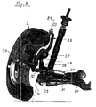
- FIGS. 2 and 3 likewise show a highly schematic form a possible practical embodiment of an independent Wheel suspension according to the invention with active camber control.
- the lower arm of the independent Wheel suspension designated 20 and by a wishbone formed at the over the only partially visible joint 21 of the intermediate carrier 22 is hinged, which projects upwards in a joint 23 ends, at which a not further shown upper handlebar attacks.
- the intermediate carrier 22 forms in the region above the wheel axle, which is determined by the journal 24, the storage for the in the vehicle longitudinal direction extending pivot axis 25, over the the axle journal 24 bearing wheel carrier 26 on the intermediate carrier 22 is articulated.
- On the intermediate carrier 22 is opposite to Wheel carrier 26 and the actuator 27 is arranged, as Stellzylinder is formed and the piston rod 28 with Distance from the pivot axis 25 is hinged to the wheel carrier 26.
- the Joints 21 and 23, over which the intermediate carrier 22 with partially not shown Rad Equipmentslenkern, such as the lower arm 20 is connected, determine the steering axis 29, and with respect to pivotal movements about the steering axis 29 is the Subcarrier 22 on the steering track lever 30 and the tie rod 31 supported in turn, in non-steered axles in not shown way to trained as a wishbone lower guide arm 20, or on the body can be supported or the steered axles with a not shown steering drive is connected, wherein this is preferably designed such that the respective Steering angle for the wheels independently and in adaptation to the respective corrected or adjusted fall corrected can be.
- Figures 2 and 3 illustrate that the wheel carrier 26 in the frame the solution according to the invention also relatively irregular Shapes in the connection between the pivot axis 25 and have the lying after the piston rod 28 joint 32 can, so that the camber adjustment according to the invention good Options for adaptation to existing basic structures offers and also in a favorable way in conjunction with driven Axes can be used.
- Camber adjustments in the order of 20 ° offer extensive Possibilities to influence the driving behavior of the vehicle, preferred in conjunction with special tires that have an asymmetrical tread contour and in which the wheel inside associated with a tread region of the tire is that convexly curved at relatively large radius of curvature is so that the tire at large camber angles not how He used this with conventional tires for multi-lane vehicles largely flat tread would do on a tire edge runs, but on a by the convex rounding formed special tread area, with regard to the respective special needs and wishes regarding material and tread design deviating to the direction of the Tire outside subsequent, flat tread area designed may be, such as a softer rubber compound can have.
- the camber adjustment can thus be, for example, in Use connection with driving programs selected by the driver can be, for example, a particularly sporty driving to allow or adapt to wintry road conditions to reach.
- the setting of the respective fall is expediently but tax or regulatory programs reserved, some also triggered by other systems of the vehicle can be, such as the so-called "brake assistant", or also of anti-lock braking systems in case of emergency braking, when a particularly high braking power is required.
- the camber adjustment offers the possibility of change the fall to a tread area of the tire, the particularly high Kkraft gleichbeihong opposite the road allows.
- Figure 4 illustrates in schematic form that the respective Camber expediently predetermined via a fall calculator which is in terms of interdependencies between the given steering geometry and changes the fall caused deviations from this with the steering computer cooperates.
- the different input variables are shown here only symbolically and it is expedient for the fall calculator at least the actual camber angle 35, the lateral acceleration 36, the vehicle speed 37, the steering angle 38, the road condition 39, the yaw rate 40 and possibly also the steering wheel angular velocity capture.
- the steering computer influencing variables are, for example shown the lateral acceleration 41, the speed 42, the steering wheel angle 43, the yaw rate 44 and the actual camber angle 45.
- the same parameters for both the fall and also needed for the steering computer these can be exchanged alternately.
- the fall calculator is the nominal camber angle for the four wheels of a vehicle, symbolically indicated by the arrows 46 and the steering computer the desired angle 47 for the wheels of the respective steered axle (s) specified.
- vehicle additional systems such as the Brake Assist, Vehicle dynamics programs, anti-lock braking systems or the like Assigned, these additional systems, as at 48 symbolically indicated with the fall calculator and / or connected to the steering computer to the camber adjustment in connection with these systems and / or in their supplement to use.
- these additional systems as at 48 symbolically indicated with the fall calculator and / or connected to the steering computer to the camber adjustment in connection with these systems and / or in their supplement to use.
- emergency braking initiated via the brake assist Adjustment of the wheels to maximum fall done The same can be done in conjunction with vehicle dynamics systems especially since the solution according to the invention individually for the wheel allows the required camber angle.
- the inventive active camber adjustment thus offers relatively low design effort and without intervention in the actual bike guidance manifold possibilities for influencing the driving behavior, and this at different Types of suspension, so that wide scope are given, in particular no limitation sporty vehicles is given. Just for the latter Vehicles, however, offer particularly far-reaching possibilities and advantages, so that related embodiments according to the invention are of particular importance.
- FIG. 5 shows a further basic illustration of a device according to the invention Wheel suspension, similar to that in Figure 1.
- the suspension also includes in this embodiment upper guide arm 4 and a lower guide arm 5, and it's the one in the body-side linkage of each Guide link 4, 5 lying pivot axis for the upper Guide link with 16 and for the lower guide link with 17 designated.
- the wheel guide associated with the guide 4 and 5 carry a leadframe 50, this leadframe 50 to the leaders 4 and 5 in relation to an upright, by its pivot points 52 and 53 opposite the guide rods 4 and 5 certain axis 51 rotatably or rotatably against the Guide arm 4 and 5 can be supported.
- the system carrier 50 is pivotable about an axis 55 with a Intermediate carrier 56 is connected, wherein the pivot axis 55 in Driving direction F runs parallel or inclined Location to the road level.
- the intermediate carrier 56 With respect to the pivot axis 55 is the intermediate carrier 56 is supported via an actuator 57, the symbolically represented by a positioning cylinder and this in turn, as indicated, opposite the system carrier 50 is supported.
- the actuator 57 about the actuator 57 thus the intermediate carrier 56 about the pivot axis 55 relative to the system carrier 50th be pivoted, with an issuing of the intermediate carrier 56th a fall of the wheel 2 to the negative corresponds.
- the intermediate carrier 56 is via a further pivot axis 58, which runs upright and preferably stands almost vertically, with the wheel carrier 59, which carries the journal 10, on the wheel 2 is rotatably mounted relative to the wheel carrier 59. With respect to the pivoting about the axis 58 is the wheel carrier 59 relative to the intermediate carrier 56 via the actuator 60th supported.
- the axle 58 can serve as a steering axis, if a Steerability of the wheel 2 should be given. In this case if the corresponding adjustment can take place via the actuator 60, in a corresponding manner, for example, depending can be acted upon by the position of the steering wheel.
- Figure 6 illustrates in the scheme according to the invention possible layers the pivot axis 55 between the system carrier 50 and intermediate carrier 56, wherein the position of the pivot axis 55 by two hinge-like Joints 61 is symbolized.
- the actuator 57 is arranged vertically offset and is for example lying above the wheel axle Pivot axis 55 in the region below the wheel axle, preferably approximately symmetrically between the joints 61.
- actuators are in the present invention actuating cylinder, Adjusting spindles or similar actuators provided, the - wear-dependent - any repetition of actuations and different positions allow.
- Actuators are useful, the only for single use are suitable, and in addition to can be used multiple times actuators.
- actuators for single use Explosive bolts preloaded spring supports or the like to carry.
- Purpose of such single use actuators is an adjustment to negative, for example Fall in emergencies, for example triggered by response of the ABS, by reaching critical cross moments or the same, to achieve stabilization of the vehicle.
Landscapes
- Engineering & Computer Science (AREA)
- Mechanical Engineering (AREA)
- Chemical & Material Sciences (AREA)
- Combustion & Propulsion (AREA)
- Transportation (AREA)
- Vehicle Body Suspensions (AREA)
Description
- Figur 1
- eine Prinzipdarstellung einer unabhängigen Radaufhängung gemäß der Erfindung, bei der zwischen Radträger und Radführungslenkern ein Zwischenträger vorgesehen ist und der Radträger gegenüber dem Zwischenträger um eine in Fahrzeuglängsrichtung verlaufende Achse schwenkbar und über ein dem Zwischenträger zugeordnetes Stellglied in seiner Sturzstellung veränderbar ist,
- Figur 2
- ein Ausführungsbeispiel einer unabhängigen Radaufhängung, die dem Prinzip gemäß Figur 1 folgt, in einer teils geschnittenen perspektivischen Rückansicht,
- Figur 3
- eine der Figur 2 entsprechende Darstellung bei in eine negative Sturzstellung geschwenktem Rad,
- Figur 4
- eine schematische Darstellung der Steuer- bzw. Regeleinheit mit wesentlichen Ein- und Ausgangsgrößen, über die für die aktive Sturzstellung des Rades der jeweilige Radsturz ermittelt und eine entsprechende Ansteuerung des Stellgliedes vorgenommen oder ausgelöst wird,
- Figur 5
- eine weitere Prinzipdarstellung einer erfindungsgemäßen Radaufhängung mit zwischen Zwischenträger und Radträger angeordneter Lenkachse, und
- Figur 6
- eine schematische Darstellung, in der die Lage der Schwenkachsen und der zugehörigen Stellglieder verdeutlicht ist.
Claims (25)
- Radaufhängung für Kraftfahrzeuge, insbesondere unabhängige Radaufhängung für Personenkraftwagen, mit einer karosserieseitigen Radführung, einem Radträger (8), der mit dem das Rad tragenden Achszapfen (10) versehen ist und mit einem zwischen Radführung und Radträger liegenden Zwischenträger (7), an dem der Radträger (8) schwenkbar angelenkt ist und gegen den der Radträger zur aktiven Einstellung des Sturzes in Bezug auf eine in Fahrzeuglängsrichtung liegende Schwenkachse (9) über ein in Fahrzeugquerrichtung wirkendes Stellglied (11) abgestützt ist,
dadurch gekennzeichnet, daß die in Fahrzeuglängsrichtung verlaufende Schwenkachse (9) des Radträgers (8) höhenversetzt zur Radachse (10) liegt und durch Ausschwenken des Radträgers (8) ein negativer Radsturz in der Größenordnung von etwa 20-30° einstellbar ist, derart, daß die Radaufstandsfläche in einen zur Radinnenseite benachbarten Laufflächenbereich des Reifens verlagert ist (Fig. 3). - Radaufhängung nach Anspruch 1,
dadurch gekennzeichnet, daß die karosserieseitige Radführung durch eine unabhängige Radaufhängung bildende Radführungslenker (4, 5; 20) gebildet ist. - Radaufhängung nach Anspruch 1,
dadurch gekennzeichnet, daß die karosserieseitige Radführung durch einen Starrachskörper gebildet ist. - Radaufhängung nach Anspruch 1,
dadurch gekennzeichnet, daß die karosserieseitige Radführung durch Führungsarme einer Verbundlenkerachse gebildet ist. - Radaufhängung nach Anspruch 4,
dadurch gekennzeichnet, daß die Schwenkachse (25), über die der Radträger (26) mit dem Zwischenträger (22) verbunden ist, oberhalb der Radachse liegt. - Radaufhängung nach einem der Ansprüche 1 bis 4,
dadurch gekennzeichnet, daß die Schwenkachse, über die der Radträger mit dem Zwischenträger verbunden ist, unterhalb der Radachse liegt. - Radaufhängung nach einem der vorhergehenden Ansprüche,
dadurch gekennzeichnet, daß die Schwenkachse (9, 25) parallel zur Radaufstandsfläche, insbesondere horizontal verläuft. - Radaufhängung nach einem der Ansprüche 1 bis 6,
dadurch gekennzeichnet, daß die Schwenkachse des Radträgers zur Radaufstandsfläche geneigt verläuft. - Radaufhängung nach Anspruch 8,
dadurch gekennzeichnet, daß die Schwenkachse des Radträgers gegenüber der Radaufstandsfläche schräg nach vorne unten verläuft. - Radaufhängung nach Anspruch 8,
dadurch gekennzeichnet, daß die Schwenkachse des Radträgers gegenüber der Radaufstandsfläche schräg nach vorne oben verläuft. - Radaufhängung nach einem der vorhergehenden Ansprüche,
dadurch gekennzeichnet, daß als Stellglied (11, 27) ein hydraulischer Aktuator, insbesondere ein Hydraulikzylinder vorgesehen ist. - Radaufhängung nach einem der Ansprüche 1 bis 10,
dadurch gekennzeichnet, daß als Stellglied ein elektrisch betriebener Aktuator, insbesondere ein Stellmotor mit Spindeltrieb vorgesehen ist. - Radaufhängung nach einem der vorhergehenden Ansprüche,
dadurch gekennzeichnet, daß das Stellglied (27) bezogen auf die Radachse gegenüberliegend zur Schwenkachse (25) angeordnet ist. - Radaufhängung nach einem der Ansprüche 1 bis 12,
dadurch gekennzeichnet, daß das Stellglied bezüglich der Radachse auf der gleichen Seite wie die Schwenkachse angeordnet ist. - Radaufhängung nach Anspruch 14,
dadurch gekennzeichnet, daß das Stellglied zwischen Schwenkachse und Radachse angeordnet ist. - Radaufhängung nach Anspruch 14,
dadurch gekennzeichnet, daß die Schwenkachse zwischen Stellglied und Radachse angeordnet ist. - Radaufhängung nach einem der vorhergehenden Ansprüche,
dadurch gekennzeichnet, daß sowohl die Anlenkung zwischen Radträger (26) und Zwischenträger (22) über die Schwenkachse (25) wie auch die Abstützung über das Stellglied (27) im Bereich, insbesondere zumindest nahezu in der lotrechten Radmittenquerebene liegt. - Radaufhängung nach einem der Ansprüche 1 bis 17,
dadurch gekennzeichnet, daß die Schwenkachse und/oder die Abstützung über das Stellglied seitlich versetzt zur lotrechten Radmittenquerebene liegen. - Radaufhängung nach Anspruch 18,
dadurch gekennzeichnet, daß die Schwenkachse und die Abstützung über das Stellglied auf verschiedenen Seiten der lotrechten Radmittenquerebene liegen. - Radaufhängung nach Anspruch 18,
dadurch gekennzeichnet, daß die Schwenkachse und die Abstützung über das Stellglied auf der gleichen Seite der lotrechten Radmittenquerebene liegen. - Radaufhängung nach einem oder mehreren der vorhergehenden Ansprüche,
dadurch gekennzeichnet, daß der Radträger (59) gegenüber dem Zwischenträger (56) um eine aufrechte Schwenkachse (58), insbesondere eine Lenkachse schwenkbar ist. - Radaufhängung nach einem oder mehreren der vorhergehenden Ansprüche,
dadurch gekennzeichnet, daß der Zwischenträger (56) gegenüber der Radführung (Führungslenker 4, 5) um eine aufrechte Schwenkachse (51), insbesondere eine Lenkachse schwenkbar ist. - Radaufhängung nach einem oder mehreren der vorhergehenden Ansprüche,
dadurch gekennzeichnet, daß die Radführung einen im Übergang der Führungslenker (4, 5) zum Zwischenträger (56) liegenden Systemträger (50) aufweist. - Radaufhängung nach einem oder mehreren der vorhergehenden Ansprüche,
dadurch gekennzeichnet, daß die in Fahrzeuglängsrichtung liegende Schwenkachse (55) zwischen Zwischenträger (52) und Radführung dem Systemträger (50) zugeordnet ist. - Radaufhängung nach einem oder mehreren der vorhergehenden Ansprüche,
dadurch gekennzeichnet, daß die zwischen Zwischenträger (56) und Radführung liegende aufrechte Schwenkachse (51) dem Systemträger (50) zugeordnet ist.
Applications Claiming Priority (2)
| Application Number | Priority Date | Filing Date | Title |
|---|---|---|---|
| DE19836440A DE19836440A1 (de) | 1998-08-12 | 1998-08-12 | Radaufhängung für Kraftfahrzeuge, insbesondere unabhängige Radaufhängung für Personenkraftwagen |
| DE19836440 | 1998-08-12 |
Publications (3)
| Publication Number | Publication Date |
|---|---|
| EP0979769A2 EP0979769A2 (de) | 2000-02-16 |
| EP0979769A3 EP0979769A3 (de) | 2001-03-28 |
| EP0979769B1 true EP0979769B1 (de) | 2003-06-18 |
Family
ID=7877241
Family Applications (1)
| Application Number | Title | Priority Date | Filing Date |
|---|---|---|---|
| EP99114753A Expired - Lifetime EP0979769B1 (de) | 1998-08-12 | 1999-07-28 | Radaufhängung für Kraftfahrzeuge, insbesondere unabhängige Radaufhängung für Personenkraftwagen |
Country Status (3)
| Country | Link |
|---|---|
| US (2) | US6347802B1 (de) |
| EP (1) | EP0979769B1 (de) |
| DE (2) | DE19836440A1 (de) |
Cited By (3)
| Publication number | Priority date | Publication date | Assignee | Title |
|---|---|---|---|---|
| DE102013222442A1 (de) | 2013-11-05 | 2015-05-07 | Voith Patent Gmbh | Radaufhängung für ein Kraftfahrzeug |
| DE102013222443A1 (de) | 2013-11-05 | 2015-05-07 | Voith Patent Gmbh | Radaufhängung für ein Kraftfahrzeug |
| CN119099261A (zh) * | 2024-10-11 | 2024-12-10 | 中国第一汽车股份有限公司 | 轮边角模块、驱动系统及车辆 |
Families Citing this family (83)
| Publication number | Priority date | Publication date | Assignee | Title |
|---|---|---|---|---|
| US6606902B2 (en) * | 2001-07-09 | 2003-08-19 | The Goodyear Tire & Rubber Company | Method of improving steering performance robustness utilizing stiffness non-uniformity in tire/wheel |
| FR2827222A1 (fr) * | 2001-07-10 | 2003-01-17 | Michelin Soc Tech | Dispositif de suspension permettant le carrossage |
| FR2833233B1 (fr) * | 2001-12-12 | 2004-02-27 | Michelin Soc Tech | Dispositif de suspension d'une roue |
| ZA200206269B (en) * | 2002-08-06 | 2003-06-25 | On Life Biotechnology Co Ltd | Motorcycle structure. |
| US20060124368A1 (en) * | 2003-03-28 | 2006-06-15 | Plishner Paul J | Vehicle with a distributed motor |
| US6880654B2 (en) * | 2003-03-28 | 2005-04-19 | Paul J. Plishner | Vehicle with a distributed motor |
| US6755429B1 (en) * | 2003-05-06 | 2004-06-29 | Ford Global Technologies, Llc | Independent suspension for rear wheels of automotive vehicle |
| DE10325056A1 (de) * | 2003-06-02 | 2004-12-23 | Fag Kugelfischer Ag | Anordnung einer schwenkbaren Radlagereinheit |
| US20050017471A1 (en) * | 2003-06-09 | 2005-01-27 | Matthew Kim | Steering with triple linkage suspension having steering adjusted camber |
| DE10330894A1 (de) | 2003-07-09 | 2005-02-10 | Daimlerchrysler Ag | Lenkbares Fahrzeug und Verfahren zur Beeinflussung der Fahrtrichtung |
| KR100552732B1 (ko) * | 2003-07-10 | 2006-02-20 | 현대자동차주식회사 | 차량의 롤오버 방지장치 |
| WO2005047030A1 (de) * | 2003-10-15 | 2005-05-26 | Schaeffler Kg | Einrichtung zum verändern des radsturzes eines rades eines kraftfahrzeuges |
| DE10358228A1 (de) * | 2003-12-12 | 2005-07-14 | Audi Ag | Anordnung für das steuerbare Verstellen der Mittellage eines einen Teil einer Radaufhängung bildenden Lenkers |
| KR100599482B1 (ko) * | 2004-10-06 | 2006-07-12 | 현대모비스 주식회사 | 액추에이터 어셈블리의 제어방법 |
| FR2884213A1 (fr) * | 2005-04-12 | 2006-10-13 | Renault Sas | Procece de controle de l'angle de carrossage des roues arriere d'un vehicule automobile et dispositif de mise en oeuvre |
| FR2888194A1 (fr) * | 2005-07-05 | 2007-01-12 | Renault Sas | Procede et systeme de commande de carrossage actif et vehicule ainsi equipe |
| FR2890631B1 (fr) * | 2005-09-15 | 2009-01-23 | Renault Sas | Systeme de direction de type sans liaison mecanique et vehicule associe |
| US7537223B2 (en) * | 2005-12-12 | 2009-05-26 | Ford Global Technologies, Llc | Vehicle wheel suspension assembly |
| FR2895721B1 (fr) * | 2005-12-29 | 2008-02-15 | Renault Sas | Procede de pilotage du carrossage des roues avant ou arriere d'un vehicule automobile equipe d'un freinage pilote et systeme de mise en oeuvre |
| FR2896753B1 (fr) | 2006-01-27 | 2008-04-11 | Renault Sas | Procede et dispositif de compensation de variations de couple |
| DE102006016762A1 (de) * | 2006-04-10 | 2007-10-31 | GM Global Technology Operations, Inc., Detroit | Achsschenkel für ein Fahrzeug |
| JP4569560B2 (ja) * | 2006-06-30 | 2010-10-27 | 株式会社エクォス・リサーチ | 車両用制御装置 |
| IL178060A (en) * | 2006-09-13 | 2010-06-30 | Davidovitch J | Vertical non- guided vehicle suspension |
| RU2320512C1 (ru) * | 2006-09-22 | 2008-03-27 | Государственное образовательное учреждение высшего профессионального образования Московский государственный технический университет "МАМИ" | Способ управления поворотными колесами наземного безрельсового транспортного средства |
| DE102006061975B4 (de) * | 2006-12-21 | 2008-11-20 | Zf Friedrichshafen Ag | Radaufhängung |
| JP4915268B2 (ja) | 2006-12-22 | 2012-04-11 | 株式会社エクォス・リサーチ | 車両用制御装置 |
| JP4848994B2 (ja) * | 2006-12-22 | 2011-12-28 | 株式会社エクォス・リサーチ | 車両用制御装置 |
| FR2910845B1 (fr) * | 2006-12-27 | 2009-02-13 | Renault Sas | Dispositif de commande du carrossage d'un vehicule. |
| DE102007011459A1 (de) * | 2007-03-09 | 2008-09-11 | Zf Friedrichshafen Ag | Kraftfahrzeug und Verfahren zum Einstellen antriebsstrangseitiger Baugruppen desselben |
| DE102007024755A1 (de) * | 2007-05-26 | 2008-11-27 | Bayerische Motoren Werke Aktiengesellschaft | Aktives Fahrwerksystem eines zweispurigen Fahrzeugs sowie Betriebsverfahren hierfür |
| US20100217491A1 (en) * | 2007-07-02 | 2010-08-26 | Equos Research Co., Ltd. | Camber angle controlling device |
| DE102007034840A1 (de) * | 2007-07-26 | 2009-01-29 | Dr. Ing. H.C. F. Porsche Aktiengesellschaft | Fahrwerkssystem für ein Kraftfahrzeug und Verfahren zur Fahrdynamikregelung |
| DE102008011367A1 (de) * | 2007-10-24 | 2009-04-30 | Audi Ag | Radaufhängung für Kraftfahrzeuge |
| JP4993110B2 (ja) * | 2007-10-31 | 2012-08-08 | 株式会社エクォス・リサーチ | キャンバ角調整機構 |
| JP5088478B2 (ja) * | 2007-10-31 | 2012-12-05 | 株式会社エクォス・リサーチ | キャンバ角調整機構 |
| JP4868165B2 (ja) * | 2007-10-31 | 2012-02-01 | 株式会社エクォス・リサーチ | キャンバ角調整機構 |
| DE102007054823A1 (de) | 2007-11-16 | 2009-05-20 | Audi Ag | Verstellvorrichtung für Radaufhängungen |
| JP2009132321A (ja) * | 2007-11-30 | 2009-06-18 | Equos Research Co Ltd | キャンバ角調整機構 |
| JP4453755B2 (ja) | 2007-12-26 | 2010-04-21 | 横浜ゴム株式会社 | 車輪の姿勢制御方法及び車輪の姿勢制御装置 |
| DE102008008207A1 (de) * | 2008-02-07 | 2009-08-13 | Robert Bosch Gmbh | Verfahren zum ausfallsicheren Betreiben eines Hybridfahrzeugs zum kontrollierten Hervorrufen von einer einen Notlauf des Fahrzeugs ermöglichenden Ersatzmaßnahme und Vorrichtung zum Durchführen dieses Verfahrens |
| CN101939179A (zh) * | 2008-02-07 | 2011-01-05 | 株式会社爱考斯研究 | 控制装置以及车辆 |
| WO2009101218A2 (es) * | 2008-02-14 | 2009-08-20 | Fundacion Robotiker | Sistema de suspensión para vehículos automóviles y vehículo automóvil que comprende dicho sistema |
| DE102008013155A1 (de) | 2008-03-07 | 2009-09-10 | Audi Ag | Verstellbarer Radträger |
| JP5240451B2 (ja) * | 2008-09-30 | 2013-07-17 | 株式会社エクォス・リサーチ | キャンバ角可変機構 |
| DE102008052161A1 (de) | 2008-10-31 | 2010-05-06 | Audi Ag | Verfahren zur Herstellung von Fahrzeugen unterschiedlicher Varianten sowie Radaufhängung für ein Fahrzeug |
| DE102009005889A1 (de) | 2009-01-23 | 2010-08-12 | Audi Ag | Verfahren zum aktiven Einstellen einer Neigung eines Rades eines Kraftwagens, insbesondere von Sturz und Spur, und entsprechende Vorrichtung |
| JP5316316B2 (ja) * | 2009-02-26 | 2013-10-16 | 株式会社エクォス・リサーチ | 車両用制御装置 |
| FR2944995B1 (fr) * | 2009-04-30 | 2013-01-18 | Peugeot Citroen Automobiles Sa | Dispositif de liaison d'une roue a une structure de vehicule comportant des moyens de reglage du carrossage |
| JP5321529B2 (ja) * | 2009-05-01 | 2013-10-23 | 株式会社エクォス・リサーチ | キャンバ制御装置 |
| DE102009021477A1 (de) | 2009-05-15 | 2010-11-18 | Audi Ag | Vorrichtung zum Verstellen von Sturz und/oder Spur |
| WO2010140237A1 (ja) * | 2009-06-03 | 2010-12-09 | トヨタ自動車株式会社 | 車両のステアリング装置及びその設定装置 |
| DE102009025227A1 (de) | 2009-06-17 | 2010-12-30 | Audi Ag | Radaufhängung für die hinteren Räder von Kraftfahrzeugen |
| DE102009032590A1 (de) * | 2009-07-10 | 2011-02-17 | GM Global Technology Operations, Inc., Detroit | Fahrzeug mit einer Vorrichtung zur Verstellung eines Sturzwinkels |
| DE102009033105B4 (de) * | 2009-07-15 | 2021-03-25 | Audi Ag | Verstellvorrichtung für Radaufhängungen von Kraftfahrzeugen |
| US8360449B2 (en) * | 2009-11-16 | 2013-01-29 | Great Lakes Sound & Vibration, Inc. | Suspension assemblies and systems for land vehicles |
| US8840126B2 (en) * | 2010-04-22 | 2014-09-23 | Edison2 Llc | Vehicle suspension system |
| US8152184B2 (en) * | 2010-04-22 | 2012-04-10 | Edison2 Llc | Vehicle suspension system |
| DE102010032073A1 (de) * | 2010-07-23 | 2012-01-26 | Audi Ag | Verfahren zum Betreiben einer mechatronischen Fahrwerkeinrichtung eines Kraftfahrzeugs |
| US8205892B2 (en) * | 2010-07-30 | 2012-06-26 | Deere & Company | Method of automatically changing wheel toe angle |
| DE102010041407A1 (de) | 2010-09-27 | 2012-03-29 | Zf Friedrichshafen Ag | Radaufhängung eines Kraftfahrzeugs |
| EP2861444B1 (de) * | 2012-06-14 | 2017-01-11 | Skf B.V | Fahrzeugsystem zur aktiven radwinkeleinstellung |
| US9085256B2 (en) * | 2013-03-13 | 2015-07-21 | Opobotics, Inc. | Self-stabilizing platform, carrier, or base |
| DE102013012124B4 (de) * | 2013-07-19 | 2021-11-11 | Audi Ag | Betriebsverfahren für ein aktives Fahrwerk eines Kraftfahrzeugs |
| JP6030521B2 (ja) * | 2013-08-30 | 2016-11-24 | 本田技研工業株式会社 | 後輪サスペンション装置 |
| DE102016001592A1 (de) * | 2016-02-11 | 2017-08-17 | Audi Ag | Verfahren zur Beeinflussung der Fahrtrichtung von Kraftfahrzeugen |
| DE102016203872A1 (de) * | 2016-03-09 | 2017-09-14 | Zf Friedrichshafen Ag | Verstellbares Fahrwerk |
| CN106627012A (zh) * | 2016-12-30 | 2017-05-10 | 上汽通用五菱汽车股份有限公司 | 一种用于多连杆式独立悬架的后车轮支架结构 |
| JP7153021B2 (ja) | 2017-01-19 | 2022-10-13 | ドォフテック ピーティーワイ リミテッド | 車両サスペンション設定を制御する為の電気機械デバイス |
| DE102017208554A1 (de) * | 2017-05-19 | 2018-11-22 | Bayerische Motoren Werke Aktiengesellschaft | Radaufhängung für ein zumindest geringfügig aktiv lenkbares Hinterrad eines zweispurigen Fahrzeugs, Achse mit einer Radaufhängung und Fahrzeug mit einer Radaufhängung |
| JP6982417B2 (ja) * | 2017-06-23 | 2021-12-17 | Ntn株式会社 | 補助転舵機能付ハブユニットおよび車両 |
| JP6909071B2 (ja) | 2017-06-23 | 2021-07-28 | Ntn株式会社 | 補助転舵機能付ハブユニットおよび車両 |
| DE102017215013B4 (de) | 2017-08-28 | 2021-02-18 | Volkswagen Aktiengesellschaft | Lenkungssteuergerät und Verfahren zur Ermittlung eines Stellsignals für eine Leistungselektronik einer Lenkeinrichtung eines Kraftfahrzeugs |
| JP6567633B2 (ja) * | 2017-11-28 | 2019-08-28 | Ntn株式会社 | 転舵機能付ハブユニットおよびこれを備えた車両 |
| US20200223270A1 (en) * | 2019-01-11 | 2020-07-16 | Tenneco Automotive Operating Company Inc. | Active Camber Control Systems and Methods |
| US11364757B2 (en) * | 2019-06-28 | 2022-06-21 | Ree Automotive Ltd | Device and method for double-arm suspension and in-wheel steering |
| KR20220128476A (ko) | 2020-01-28 | 2022-09-20 | 리 오토모티브 리미티드 | 휠 중심에서 벗어난 아암을 갖는 휠 서스펜션 시스템 |
| WO2022077059A1 (en) | 2020-10-13 | 2022-04-21 | Doftek Pty Ltd | Wheel alignment systems |
| US12077234B2 (en) * | 2020-12-31 | 2024-09-03 | Ree Automotive Ltd. | Steering and suspension mechanism |
| US20220305857A1 (en) * | 2021-03-24 | 2022-09-29 | Mf Ip Holding, Llc | Suspension system for a vehicle and method of adjusting rear control arm geometry for same |
| US20230074160A1 (en) * | 2021-04-01 | 2023-03-09 | Wadih Geahchan | Adaptive tires traction control |
| KR102313267B1 (ko) * | 2021-04-14 | 2021-10-14 | 서한산업(주) | 전동식 독립 조향장치 |
| US11772442B2 (en) * | 2021-07-23 | 2023-10-03 | Rivian Ip Holdings, Llc | Offset steering axis knuckle system |
| KR20240043826A (ko) * | 2022-09-27 | 2024-04-04 | 현대자동차주식회사 | 차량용 서스펜션 장치 |
Family Cites Families (14)
| Publication number | Priority date | Publication date | Assignee | Title |
|---|---|---|---|---|
| DE46782C (de) | fr. j GAPPISCH in Dresden | Abort mit durch Sandverschlufs ge-; dichtetem Deckel und theilbarem Sitzbrett | ||
| US3175842A (en) * | 1962-04-05 | 1965-03-30 | Lubbock Machine & Supply | Crank arm axle |
| DD46782A1 (de) * | 1962-12-08 | 1966-06-15 | Karl Wehsely | Vorrichtung zur Veränderung des Winkels zwischen Radebene und Achse bei landwirtschaftlichen Traktoren |
| DE3139792A1 (de) * | 1981-10-07 | 1983-04-21 | Dr.Ing.H.C. F. Porsche Ag, 7000 Stuttgart | "radaufhaengung fuer eine hinterachse von kraftfahrzeugen" |
| FR2561193B1 (fr) * | 1984-03-15 | 1987-04-17 | Honda Motor Co Ltd | Systeme de commande d'alignement des roues pour vehicules |
| US4752079A (en) * | 1985-07-31 | 1988-06-21 | Surfco | Enhanced traction wheel assembly |
| JPS62125907A (ja) * | 1985-11-28 | 1987-06-08 | Isuzu Motors Ltd | 可変サスペンシヨンジオメトリ装置 |
| EP0246116B1 (de) * | 1986-05-16 | 1992-04-15 | Honda Giken Kogyo Kabushiki Kaisha | Sturzregelungssystem für ein Kraftfahrzeug |
| JPS63162313A (ja) * | 1986-12-26 | 1988-07-05 | Honda Motor Co Ltd | 自動車のサスペンシヨン装置 |
| DE3928135A1 (de) * | 1988-08-31 | 1990-03-01 | Volkswagen Ag | Radaufhaengung fuer kraftfahrzeuge, insbesondere fuer personenkraftwagen |
| JP2714969B2 (ja) * | 1989-01-13 | 1998-02-16 | マツダ株式会社 | 自動車のサスペンション装置 |
| US4973075A (en) * | 1989-12-04 | 1990-11-27 | Chrysler Corporation | Independent suspension toe and camber adjustment system |
| DE4020547A1 (de) * | 1990-06-28 | 1992-01-02 | Porsche Ag | Vorrichtung zur aktiven verstellung eines kraftfahrzeugrades |
| US5620199A (en) * | 1993-12-10 | 1997-04-15 | Hyundai Motor Company | Suspension system for vehicle |
-
1998
- 1998-08-12 DE DE19836440A patent/DE19836440A1/de not_active Withdrawn
-
1999
- 1999-07-28 DE DE59905979T patent/DE59905979D1/de not_active Expired - Fee Related
- 1999-07-28 EP EP99114753A patent/EP0979769B1/de not_active Expired - Lifetime
- 1999-08-12 US US09/371,988 patent/US6347802B1/en not_active Expired - Lifetime
-
2001
- 2001-11-30 US US10/000,234 patent/US6634654B2/en not_active Expired - Fee Related
Cited By (5)
| Publication number | Priority date | Publication date | Assignee | Title |
|---|---|---|---|---|
| DE102013222442A1 (de) | 2013-11-05 | 2015-05-07 | Voith Patent Gmbh | Radaufhängung für ein Kraftfahrzeug |
| DE102013222443A1 (de) | 2013-11-05 | 2015-05-07 | Voith Patent Gmbh | Radaufhängung für ein Kraftfahrzeug |
| WO2015067638A2 (de) | 2013-11-05 | 2015-05-14 | Voith Patent Gmbh | Radaufhängung für ein kraftfahrzeug |
| DE102013222442B4 (de) * | 2013-11-05 | 2016-12-15 | Brist Axle Systems S.R.L. | Radaufhängung für ein lenkbares Antriebsrad bei einem Kraftfahrzeug |
| CN119099261A (zh) * | 2024-10-11 | 2024-12-10 | 中国第一汽车股份有限公司 | 轮边角模块、驱动系统及车辆 |
Also Published As
| Publication number | Publication date |
|---|---|
| US6347802B1 (en) | 2002-02-19 |
| EP0979769A2 (de) | 2000-02-16 |
| US20020036385A1 (en) | 2002-03-28 |
| EP0979769A3 (de) | 2001-03-28 |
| US6634654B2 (en) | 2003-10-21 |
| DE59905979D1 (de) | 2003-07-24 |
| DE19836440A1 (de) | 2000-02-24 |
Similar Documents
| Publication | Publication Date | Title |
|---|---|---|
| EP0979769B1 (de) | Radaufhängung für Kraftfahrzeuge, insbesondere unabhängige Radaufhängung für Personenkraftwagen | |
| EP1997715B1 (de) | Aktives Fahrwerksystem eines zweispurigen Fahrzeugs sowie Betriebsverfahren hierfür | |
| DE68926394T2 (de) | Fahrzeugaufhängungssystem | |
| DE102015110470B4 (de) | Fahrzeug und ein aufhängungssystem für das fahrzeug | |
| EP0656270A1 (de) | Radaufhängung | |
| DE102013216029A1 (de) | Lenkbare Vorderachse für Räder eines zweispurigen Kraftfahrzeugs und zweispuriges Kraftfahrzeug mit einer solchen Vorderachse | |
| EP2246207B1 (de) | Flughafenschlepper mit Luftfederung | |
| DE102015203262A1 (de) | Unabhängige integralfünflenkeraufhängungssysteme | |
| DE102004007549B4 (de) | Verfahren zum Betrieb eines aktiven Fahrwerksystems | |
| DE102017200006B4 (de) | Neigefahrzeug | |
| DE102017212546B4 (de) | Achsenbaugruppe | |
| DE102006055294A1 (de) | Einzelradaufhängung für Kraftfahrzeug mit aktiver Spurverstellung | |
| DE1630134C3 (de) | Radaufhängung, insbesondere für die Hinterräder von Kraftfahrzeugen | |
| DE102019213969B4 (de) | Verfahren und Vorrichtung zur Anpassung des Fahrwerks eines Kraftfahrzeuges sowie Steuergerät | |
| EP1741577B1 (de) | Radaufhängung für die gelenkten Räder eines Kraftfahrzeuges | |
| EP0556464A1 (de) | Einzelradaufhängung für Hinterräder eines Kraftfahrzeugs | |
| EP2342093A1 (de) | Verfahren zur herstellung von fahrzeugen unterschiedlicher varianten sowie radaufhängung für ein fahrzeug | |
| EP3359440B1 (de) | Mehrspuriges kraftfahrzeug | |
| DE2800549A1 (de) | Im niveau geregeltes kraftfahrzeug | |
| DE19915214A1 (de) | Einzelradaufhängung für Kraftfahrzeuge | |
| EP3127791B1 (de) | Vorrichtung zur verbesserung der fahrsicherheit von knickgelenkten fahrzeugen | |
| DE102014008620A1 (de) | Fahrwerksystem eines Fahrzeuges und Verfahren zum Abheben wenigstens eines Fahrzeugrades eines Fahrzeuges | |
| DE102004034118A1 (de) | Kraftfahrzeug mit mindestens einer verstellbaren Radaufhängung | |
| DE4339856C2 (de) | Radaufhängung, insbesondere für die Hinterräder von Kraftfahrzeugen | |
| WO2010045999A1 (de) | Radaufhängung mit einstellvorrichtungen für spur und sturz sowie verfahren zur spur- und sturz-einstellung |
Legal Events
| Date | Code | Title | Description |
|---|---|---|---|
| PUAI | Public reference made under article 153(3) epc to a published international application that has entered the european phase |
Free format text: ORIGINAL CODE: 0009012 |
|
| AK | Designated contracting states |
Kind code of ref document: A2 Designated state(s): DE FR GB IT |
|
| AX | Request for extension of the european patent |
Free format text: AL;LT;LV;MK;RO;SI |
|
| PUAL | Search report despatched |
Free format text: ORIGINAL CODE: 0009013 |
|
| AK | Designated contracting states |
Kind code of ref document: A3 Designated state(s): AT BE CH CY DE DK ES FI FR GB GR IE IT LI LU MC NL PT SE |
|
| AX | Request for extension of the european patent |
Free format text: AL;LT;LV;MK;RO;SI |
|
| RIC1 | Information provided on ipc code assigned before grant |
Free format text: 7B 62D 17/00 A, 7B 62D 6/04 B, 7B 60G 17/015 B, 7B 60G 3/26 B, 7B 60G 7/00 B |
|
| 17P | Request for examination filed |
Effective date: 20010322 |
|
| AKX | Designation fees paid |
Free format text: DE FR GB IT |
|
| GRAH | Despatch of communication of intention to grant a patent |
Free format text: ORIGINAL CODE: EPIDOS IGRA |
|
| GRAH | Despatch of communication of intention to grant a patent |
Free format text: ORIGINAL CODE: EPIDOS IGRA |
|
| GRAA | (expected) grant |
Free format text: ORIGINAL CODE: 0009210 |
|
| AK | Designated contracting states |
Designated state(s): DE FR GB IT |
|
| REG | Reference to a national code |
Ref country code: GB Ref legal event code: FG4D Free format text: NOT ENGLISH |
|
| REF | Corresponds to: |
Ref document number: 59905979 Country of ref document: DE Date of ref document: 20030724 Kind code of ref document: P |
|
| GBT | Gb: translation of ep patent filed (gb section 77(6)(a)/1977) |
Effective date: 20031021 |
|
| ET | Fr: translation filed | ||
| PLBE | No opposition filed within time limit |
Free format text: ORIGINAL CODE: 0009261 |
|
| STAA | Information on the status of an ep patent application or granted ep patent |
Free format text: STATUS: NO OPPOSITION FILED WITHIN TIME LIMIT |
|
| 26N | No opposition filed |
Effective date: 20040319 |
|
| REG | Reference to a national code |
Ref country code: FR Ref legal event code: CD Ref country code: FR Ref legal event code: CA |
|
| PGFP | Annual fee paid to national office [announced via postgrant information from national office to epo] |
Ref country code: IT Payment date: 20091223 Year of fee payment: 11 Ref country code: GB Payment date: 20091218 Year of fee payment: 11 Ref country code: FR Payment date: 20100108 Year of fee payment: 11 |
|
| PGFP | Annual fee paid to national office [announced via postgrant information from national office to epo] |
Ref country code: DE Payment date: 20091222 Year of fee payment: 11 |
|
| GBPC | Gb: european patent ceased through non-payment of renewal fee |
Effective date: 20100728 |
|
| REG | Reference to a national code |
Ref country code: FR Ref legal event code: ST Effective date: 20110331 |
|
| PG25 | Lapsed in a contracting state [announced via postgrant information from national office to epo] |
Ref country code: DE Free format text: LAPSE BECAUSE OF NON-PAYMENT OF DUE FEES Effective date: 20110201 |
|
| REG | Reference to a national code |
Ref country code: DE Ref legal event code: R119 Ref document number: 59905979 Country of ref document: DE Effective date: 20110201 |
|
| PG25 | Lapsed in a contracting state [announced via postgrant information from national office to epo] |
Ref country code: FR Free format text: LAPSE BECAUSE OF NON-PAYMENT OF DUE FEES Effective date: 20100802 Ref country code: IT Free format text: LAPSE BECAUSE OF NON-PAYMENT OF DUE FEES Effective date: 20100728 |
|
| PG25 | Lapsed in a contracting state [announced via postgrant information from national office to epo] |
Ref country code: GB Free format text: LAPSE BECAUSE OF NON-PAYMENT OF DUE FEES Effective date: 20100728 |