EP0979770B1 - Vorrichtung zur Nachbildung zumindest eines Teilbereichs einer Fahrzeugkarosserie - Google Patents
Vorrichtung zur Nachbildung zumindest eines Teilbereichs einer Fahrzeugkarosserie Download PDFInfo
- Publication number
- EP0979770B1 EP0979770B1 EP19990114779 EP99114779A EP0979770B1 EP 0979770 B1 EP0979770 B1 EP 0979770B1 EP 19990114779 EP19990114779 EP 19990114779 EP 99114779 A EP99114779 A EP 99114779A EP 0979770 B1 EP0979770 B1 EP 0979770B1
- Authority
- EP
- European Patent Office
- Prior art keywords
- components
- vehicle
- component
- parts
- fastening
- Prior art date
- Legal status (The legal status is an assumption and is not a legal conclusion. Google has not performed a legal analysis and makes no representation as to the accuracy of the status listed.)
- Expired - Lifetime
Links
- 238000000034 method Methods 0.000 title description 6
- 238000004519 manufacturing process Methods 0.000 claims description 15
- 229910052751 metal Inorganic materials 0.000 claims description 8
- 239000002184 metal Substances 0.000 claims description 8
- 239000007769 metal material Substances 0.000 claims description 7
- 229910000838 Al alloy Inorganic materials 0.000 claims description 3
- 238000009434 installation Methods 0.000 description 12
- 239000000463 material Substances 0.000 description 12
- 238000012360 testing method Methods 0.000 description 8
- 238000007789 sealing Methods 0.000 description 7
- 239000011343 solid material Substances 0.000 description 4
- 229910052782 aluminium Inorganic materials 0.000 description 3
- XAGFODPZIPBFFR-UHFFFAOYSA-N aluminium Chemical compound [Al] XAGFODPZIPBFFR-UHFFFAOYSA-N 0.000 description 3
- 230000008901 benefit Effects 0.000 description 3
- 238000010276 construction Methods 0.000 description 3
- 238000013461 design Methods 0.000 description 3
- 238000012545 processing Methods 0.000 description 3
- 238000003908 quality control method Methods 0.000 description 3
- 229910000831 Steel Inorganic materials 0.000 description 2
- 230000000712 assembly Effects 0.000 description 2
- 238000000429 assembly Methods 0.000 description 2
- 230000006378 damage Effects 0.000 description 2
- 238000011990 functional testing Methods 0.000 description 2
- 230000003993 interaction Effects 0.000 description 2
- 238000011835 investigation Methods 0.000 description 2
- 238000003754 machining Methods 0.000 description 2
- 238000000465 moulding Methods 0.000 description 2
- 230000008569 process Effects 0.000 description 2
- 238000000926 separation method Methods 0.000 description 2
- 239000010959 steel Substances 0.000 description 2
- 230000000007 visual effect Effects 0.000 description 2
- 239000013585 weight reducing agent Substances 0.000 description 2
- 238000003466 welding Methods 0.000 description 2
- 229920000049 Carbon (fiber) Polymers 0.000 description 1
- OWYWGLHRNBIFJP-UHFFFAOYSA-N Ipazine Chemical compound CCN(CC)C1=NC(Cl)=NC(NC(C)C)=N1 OWYWGLHRNBIFJP-UHFFFAOYSA-N 0.000 description 1
- 229910000639 Spring steel Inorganic materials 0.000 description 1
- 238000004026 adhesive bonding Methods 0.000 description 1
- 238000004378 air conditioning Methods 0.000 description 1
- 229910045601 alloy Inorganic materials 0.000 description 1
- 239000000956 alloy Substances 0.000 description 1
- 230000005540 biological transmission Effects 0.000 description 1
- 230000015572 biosynthetic process Effects 0.000 description 1
- 239000004917 carbon fiber Substances 0.000 description 1
- 238000005266 casting Methods 0.000 description 1
- 239000004927 clay Substances 0.000 description 1
- 239000002131 composite material Substances 0.000 description 1
- 238000012937 correction Methods 0.000 description 1
- 230000007797 corrosion Effects 0.000 description 1
- 238000005260 corrosion Methods 0.000 description 1
- 238000005520 cutting process Methods 0.000 description 1
- 238000011161 development Methods 0.000 description 1
- 230000000694 effects Effects 0.000 description 1
- 238000010438 heat treatment Methods 0.000 description 1
- 238000010348 incorporation Methods 0.000 description 1
- 238000005304 joining Methods 0.000 description 1
- 230000014759 maintenance of location Effects 0.000 description 1
- 230000013011 mating Effects 0.000 description 1
- 230000007246 mechanism Effects 0.000 description 1
- VNWKTOKETHGBQD-UHFFFAOYSA-N methane Chemical compound C VNWKTOKETHGBQD-UHFFFAOYSA-N 0.000 description 1
- 238000003801 milling Methods 0.000 description 1
- 238000005192 partition Methods 0.000 description 1
- 238000005096 rolling process Methods 0.000 description 1
- 239000007858 starting material Substances 0.000 description 1
- 239000003351 stiffener Substances 0.000 description 1
- 239000000725 suspension Substances 0.000 description 1
- 230000007704 transition Effects 0.000 description 1
- 238000009423 ventilation Methods 0.000 description 1
Images



Classifications
-
- B—PERFORMING OPERATIONS; TRANSPORTING
- B62—LAND VEHICLES FOR TRAVELLING OTHERWISE THAN ON RAILS
- B62D—MOTOR VEHICLES; TRAILERS
- B62D65/00—Designing, manufacturing, e.g. assembling, facilitating disassembly, or structurally modifying motor vehicles or trailers, not otherwise provided for
Definitions
- the invention relates to a device for simulating at least one subregion a vehicle body for the purpose of tuning vehicle parts, as is known for example from DE 43 11 647 C2. Such devices are also called cubing superstructures.
- DE 43 11 647 A1 discloses a device with a plurality of stiffer Frame parts, on the insides for the purpose of mecaniccubings pieces of equipment are arranged.
- the object of the invention is to develop the known devices.
- Core idea according to claim 1 is the internal structure of a Reproduce vehicle body with high dimensional accuracy and reference parts of outer skin components which provide the outer skin components of Imitate vehicle body with high dimensional accuracy.
- no separate inner framework is provided; much more is also the inner structure at least in some areas of the sheet metal structure of Vehicle body imitated immediately.
- the reference parts over a long time their dimensional and shape accuracy maintained, they are in accordance with the Invention made of a metallic material.
- the reference parts can at least partially detached from the internal structure and against be tuned Shell components are replaced.
- individual reference parts be replaced by models (sample parts) or standard parts, with the adjacent Reference parts an exact assessment of the joint image and the transitions enable.
- Movable outer skin components doors, flaps, etc.
- the reference parts to be checked components of the vehicle exterior eg bumpers, headlights, lights, trim strips, etc.
- the device of the invention in its external appearance - apart the material used - a styling model of the vehicle made of clay is similar, is suitable in a particularly advantageous manner for quality control in advance and during the start of production of a new vehicle model.
- the device is independent of the availability of a prototype body shell or without Recourse to standard bodies for quality control. she can Furthermore, advantageously for testing the dimensional and shape retention of Vehicle parts used throughout the production period of the vehicle by making a reference for the released series production close to production (Design target) is available at the changes of the Series status by replacing the respective changed components easily can be represented.
- Design target the reference for the released series production close to production
- Updated cubing models will create a reference that will ensure quality facilitated in series production. It is particularly useful, certain Sub-scopes of the body (front, rear, etc.) in own Represent devices and the respective production areas or the to the respective suppliers for quality control purposes.
- reference parts of equipment parts of the vehicle the so far from model material (eg "Ureol” the Fa. Ciba Geigy) or from Carbon fiber are made of a metallic material.
- model material eg "Ureol” the Fa. Ciba Geigy
- Carbon fiber are made of a metallic material.
- a consistently high dimensional and form accuracy achieved over a longer Period (for example, over the entire production period of a vehicle) serve as a reference, a consistently high dimensional and form accuracy achieved.
- the term "fitting part” includes all attachable to the body shell Components and attachments, especially in the interior of the vehicle. This can be done by the installation of a built-in or accessory in an environment of reference parts is formed, without the use of measuring equipment, a test of dimensional accuracy be made.
- the components of the reference parts of the skin components or the reference parts of fittings according to claim 3 made of a light metal material.
- the individual components are made by machining, for example by milling based on CAD data, manufactured with high dimensional accuracy.
- Preferred material of the components are cast aluminum or rolled alloys, which are easy to work with and are characterized by a low weight have sufficient strength and stiffness characteristics.
- the reference parts of the skin components are individually from the removable inner structure and adjacent reference parts, wherein the Fixing the reference parts is designed so that a disassembly more Reference parts or other components of the internal structure usually not is required. These are the parting planes between the individual components to choose and design accordingly.
- the Device according to the invention according to claim 5 also for the mecanical in be used particularly advantageously.
- an "extended mecaniccubing be performed by also clearances and cavities of the Body shell be modeled on the device according to the invention.
- this are cavities in a B-pillar (eg for a belt retractor), in the parcel shelf (eg. As for speakers, forced ventilation, belt retractor, etc.) and in the range of Sill, wheel arch and front wall (eg for control units, grommets for carrying of lines, etc.).
- the housing may, for example, harnesses and of channels for the heating or air conditioning in open spaces of the replicated body are examined. Also it is possible the installation larger or more complex systems (eg instrument panel, seat, airbag system, fürlade overlooked between passenger and luggage space, etc.) to simulate. Besides can also Freiauerkeits conductede on moving components, such as Window lifts, sunroofs, locking systems, etc. are performed.
- functional surfaces are on individual components of the device intended for equipment. Dimensionally accurate contact surfaces serve or installation tests, for example, of locking systems for doors and flaps. Flanges are especially for the attachment of edge protection and sealing profiles suitable.
- On reference parts of the outer structure (outer skin components) can Covering elements, moldings, company emblems, covers for rain moldings, Bumpers, headlights, lights, windscreens, etc. attached become.
- edge-side areas of low wall thickness with an insert made of a material of high strength (eg spring steel), in order to make a faithful reproduction in this area to reach the body.
- a material of high strength eg spring steel
- the outer skin components ie reference parts, sample parts or serial outer skin components
- the vehicle interior side components ie reference parts according to Claim 2, conventional pattern parts or standard components
- the standard mounting situation is reproduced.
- the outer skin components eg door outer skin
- vehicle exterior Equipment parts eg headlights
- Hinges fall in the broader sense under the term of fasteners.
- the inner Structure fastening devices for vehicle interior components such as trim parts, Belt retractor, control devices, etc. provided.
- the fastening devices preferably have interchangeable inserts (Claim 9). This is damage or destruction of a fastening device a trouble-free replacement of the fastening device possible.
- the Fastening devices can for screw and / or clip attachment of Be designed components (claim 10). Thus, one of the series attachment appropriate Fixing already be done on Cubing structure.
- the fasteners may be attached to components of the inner or the be provided external structure and serve the attachment of equipment of all kinds such. B trim parts, electric, pneumatic or hydraulic lines, control units, electromotive actuators etc.
- the Fasteners are for example of threaded inserts, Clips, welding or threaded bolts, mounting brackets, dowel pins etc. formed. In particular, welding bolts, especially ground area, can in Cubing structure set much easier and exchanged against each other, as is the case with a body shell.
- the wall thickness of large-area components of the outer structure in planar Enlarged areas (claim 12), either over a large area or by frame-like ribbing.
- the increase in wall thickness is in the Areas uncritical, introduced in the no additional attachments or functional components become. This is especially the case in areas with soundproofing mats are deposited.
- the device In addition to the position of the device according to the invention in the vehicle network can the device also be provided with wheels (claim 13). This will a simple transport of the device achieved and in addition the possibility opened, the replica vehicle in its appearance complete with the to inspect standard wheels.
- the device is on the underside of a pivotable base plate arranged.
- the device can accordingly the assembly process in the series production of the vehicle in a position obliquely be brought up or down, so that the mountability of individual components on the underside of the vehicle in a realistic manner can be examined.
- the device can be like the corresponding one Bodywork on a mounting bracket passed through the production Be sure to mount all the above sizes under realistic conditions to try out.
- Fastening devices for vehicle underside attachments are at a Apparatus according to claim 14 corresponding to the standard attachment points provided on the underbody of the vehicle. Again, you can all common joining techniques according to or deviating from the fixing modalities of the mass-produced vehicle.
- inventive Devices or subareas of devices according to the invention Suppliers of the vehicle manufacturer are handed over, so that at vehicle manufacturers and supplier alike a uniform vote of the components dimensionally accurate reference models.
- inventive Subassembly devices in particular suppliers of the vehicle manufacturer, be used, for. B. for the interior (cockpits, door panels, luggage compartments, Roof linings, columns, etc.) or in the outer skin area (Bumper systems, sill covers, lights, headlights, etc.).
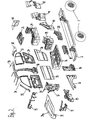
- Figures 1 and 2 represent the left half of a designated in its entirety by 1 Device for simulating a vehicle body.
- the device 1 represents the entire outer skin of the vehicle except the underbody as well large areas of the interior of the body shell with high dimensional accuracy.
- the device 1 is constructed on a base plate 2, wherein additionally standard Vehicle wheels 3 are mounted on the device 1.
- the device 1 is made in the example shown from a total of 98 individual Components together and is a self-supporting image of the motor vehicle educated.
- the entire device 1 has a weight of about 2.5 t.
- the components the left half of the vehicle are shown explosively in Figure 2, wherein in the representation also assemblies are contained, which consist of several individual components put together.
- the individual components are accurate made of ⁇ 0.2 mm and are preferably made of aluminum alloys (Rolling or casting material), for example, AlMg4,5Mn.
- Another example for a starting material for the components of the device 1 is cast aluminum Made of Unifond90 (G-AlZn10Si8Mg) without scrap, cast without cavities and sandblasted.
- the device 1 is divided essentially into an inner and an outer Structure.
- the internal structure of the device 1 consists of the following components and individual components: Front wall 11 (four components), end wall 12 (three components), front wheel house 13, lower part of the A-pillar 14, support tube 15, front floor panel 16 (fifteen components), front sill 17, B-pillar 18, rear Bottom plate 19 (nine components), rear sill 20, luggage compartment 21 (ten Components) and upper partition 22.
- Front wall 11 four components
- end wall 12 three components
- front wheel house 13 lower part of the A-pillar 14
- support tube 15 front floor panel 16 (fifteen components), front sill 17, B-pillar 18, rear Bottom plate 19 (nine components), rear sill 20, luggage compartment 21 (ten Components) and upper partition 22.
- the outer structure of the device 1 is formed by reference parts, which are the Imitate outer skin components.
- reference parts which are the Imitate outer skin components.
- these are: Front flap 31, front Sidewall 32, front door outer skin 33, front window frame 34, A-pillar 35, rear door outer skin 36, rear window frame 37, C-pillar 38, roof 39, rear Side frame with front, middle and rear section (reference numbers 40, 41 and 42) and tailgate 43.
- the B-pillar 18 may be due to the outboard Visible surface in its upper section readily as a component of external structure are classified.
- a separation between inner and outer structure are in other components such as the B-pillar 18, the front door 31, the window frame 34 and 37, the A-pillar 35, the roof 39, the rear side frames 40 to 42 and the tailgate 43 merged these two structures into a single structure.
- Essential to the invention is that both the outer and inner contour of the skin components as well as the contour of the inner structure are executed true to the original. This results, for example, between the door inner panels 23 and 24 and the outside door skin 33 or 36 free spaces at which installation tests of components, such as a side window, a window lift, etc. performed can be. Also clearances in the sill 17 and 20 below a not shown Sill panel, in the area of the end wall 12, in the area of the floor panel 16 or 19 or the luggage compartment 21 can for the standard Installation of components, such as control units, cables, etc. used become.
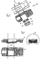
- FIGS. 3 and 4 show a device, designated in its entirety by 50, which simulates the area of the underbody of a vehicle body.
- the Device 50 is attached to a base plate 51 with a hanger of two arcuate Suspension devices 52 connected.
- the device 50 is the same as shown in Figures 1 and 2 device 1 of a variety of Components, of which in Figure 3, only four components 53 to 56 of the floor assembly and a sill member 57 are shown separately.
- the device 50 (shown without the components 53 to 56), the base plate 51 above the replicated vehicle section.
- the base plate 51 By pivoting the base plate by 180 ° is the modeled Area of the subfloor on top and is for installation tests and assessments easily accessible.
- the base plate 51 can of course in any Intermediate positions are pivoted to the situation on a mounting bracket to simulate in the final assembly of a motor vehicle.
- Figure 5 shows the composite of the components 23 and 33 door of the device 1 in cross section.
- the component 23 is in its upper area 60 from a solid material, which ends in a flange 61 on the upper side. Down sets the simulated door inner panel 23 continues in a thin-walled structure 62, However, compared to the plate thickness of the standard shell component, as in Area A is shown, due to the required rigidity and strength having correspondingly increased wall thickness.
- a receptacle 63 In the middle area of the door inner panel 23 is integrally formed on the structure 62, a receptacle 63, a in its entirety with 65 designated connecting element receives.
- the connecting element 65 consists of a receptacle 66 and an adapter 67, as on already known from DE 196 20 465 A1.
- the component 33 (outer door skin) also exists in its upper area 70 from a solid material with integrally formed flange 71. At the bottom of the sits imitated outer door panel 33 in a flat section 72, the same how the area 62 of the door inner panel 23 is stiffened. For comparison is in the range B shows the original sheet thickness.
- a receptacle 73 forms the outer Counterpart for the connection of the connecting element 65.
- Figure 6 shows an A-pillar 35a made of sheet steel in cross-section, in two chambers 35b and 35c is divided.
- the A-pillar 35a has a first and a second Flange 81 and 82, which is the investment of a windshield, not shown or the inclusion of a sealing profile 83 serve.
- Einsteckbefestiger 85 in which a diaphragm 86 by means of a receiving pin 87 is inserted.
- the door-side portion 93 of the panel 86 is fixed in the sealing profile 83.
- Figure 7 shows the A-pillar 35 of the device 1, the difference for sheet metal component 35a of Figure 6 is designed as a solid material.
- the A-pillar 35 corresponds exactly to the outer contour of the A-pillar 35a in sheet metal construction.
- the flanges 81 and 82 are corresponding to the series part with executed high dimensional accuracy, so that an absolutely faithful contact surface exists for the windshield and the sealing profile 83 has the same effect can be attached to the A-pillar 35a.
- the in FIG. 7 is designed as a sample part close to production or as a standard component inserted into the A-pillar 35 a Peredbuchse 88.
- This passport sleeve 88 carries in their interior a standard Einsteckbefestiger 85, the thus in analog Way the guide pin 87 of the aperture 86 can accommodate.
- Alternative to the passport 88 also a screw jack can be used, with advantages in terms the interchangeability and susceptibility to corrosion.
- a pattern part 90 which consists of a metallic Material exists.
- a pattern part 90 For connection of the sample part 90 is in the modeled A-pillar 35 an integrally formed on the pattern part 90 fitting bushing 88a used, which positions the pattern part 90 exactly to the A-pillar.
- Sample parts according to Figure 8 have a limited due to the materials used Dimensional stability and dimensional stability over time.
- a pattern part as a reference part during the entire production cycle of a vehicle type becomes an additional to the series status additional Fixing points proposed to the device 1 (not shown).
- such pattern parts in the same way as the components of Devices 1 or 50 are made of light metal to be independent of the duration of use to achieve a consistent dimensional stability and dimensional stability.
- flat areas of outer skin components can also be milled in a nearly true-to-original material thickness of 2 mm, whereby both the outer skin and the space available on the inside can be displayed.
- This can be surfaces of about 300 x 300 mm 2 are shown, however, must have a circumferential frame to provide appropriate stability, especially at the joints between two components.
- the individual components of the devices 1 and 50 are designed so that they form a self-supporting structure, with wall thicknesses that provide sufficient Ensure rigidity.
- the inner structure as well as larger sections of the outer structure are divided so that between the components are preferred level separation surfaces arise to the assembly and the exchange of individual To facilitate components. Due to the limited size and the comparatively Low weight simplifies compared to large-sized components the production as well as the subsequent processing with changes of individual Components. In addition, an improved handling in the construction of the device or when replacing a component achieved. Also can with dimensional or geometric changes of a body section of individual components be exchanged for new components with little effort.
- the individual components are at their boundary or division surfaces over used Pdentsbuchsen and dowels pinned together and then to Secured the connection screwed, the screw preferably from are accessible on the outside so that the respective outer skin components (eg B pillar, Roof, sills, side frames, etc.) without disassembly of adjacent components can be solved or fixed.
- the fasteners (Pins, screws) in a fixed grid, for example in a 100 mm grid, to be provided.
- the components of the Device 1 or 50 connected to the base plate 2 and 51, respectively.
- the mold division is In addition to choose so that different body styles of Vehicle by replacing as few components as possible can.
- outer skin components front, tailgate, roof, Side frames, etc.
Landscapes
- Engineering & Computer Science (AREA)
- Manufacturing & Machinery (AREA)
- Chemical & Material Sciences (AREA)
- Combustion & Propulsion (AREA)
- Transportation (AREA)
- Mechanical Engineering (AREA)
- Body Structure For Vehicles (AREA)
- Optical Measuring Cells (AREA)
Description
- Figur 1
- eine erfindungsgemäße Vorrichtung in perspektivischer Seitenansicht,
- Figur 2
- eine Explosionsdarstellung mit den einzelnen Komponenten der Vorrichtung gemäß Figur 1,
- Figur 3
- eine Vorrichtung zur Nachbildung des Bodenbereiches eines Kraftfahrzeuges in auseinandergezogener Darstellung,
- Figur 4
- die Vorrichtung gemäß Figur 3 in Seiten-, Unter- und Vorderansicht,
- Figur 5
- einen Schnitt durch die Vorrichtung gemäß Figur 1 im Bereich der Tür,
- Figur 6
- eine Schnittdarstellung durch den Bereich einer Säule eines serienmäßig hergestellten Fahrzeugs, mit einem serienmäßig hergestellten Innenverkleidungsteil,
- Figur 7
- eine Schnittdarstellung eines Referenzbauteils, das der Säule aus Figur 6 entspricht, mit einem serienmäßig hergestellten Innenverkleidungsteil und
- Figur 8
- eine der Figur 7 entsprechende Darstellung, mit einem Musterteil anstelle des serienmäßig hergestellten Innenverkleidungsbauteils.
Claims (14)
- Vorrichtung (1, 50) zur Nachbildung zumindest eines Teilbereiches einer Fahrzeugkarosserie zum Zweck der Abstimmung von Fahrzeugteilen, mit einer tragenden inneren Struktur aus einem metallischen Werkstoff, wobei
eine innere Struktur von Komponenten (11 bis 22) gebildet wird, die zumindest in Teilbereichen die Blechstruktur der Fahrzeugkarosserie unmittelbar nachbilden, wobei an der inneren Struktur Referenzteile (31 bis 42) von Außenhautbauteilen der Fahrzeugkarosserie angeordnet sind, wobei die Referenzteile (31 bis 42) aus einem metallischen Werkstoff bestehen und zumindest teilweise von der inneren Struktur abnehmbar sind. - Vorrichtung nach Anspruch 1, wobei
an der Vorrichtung wenigstens ein Referenzteil eines Ausstattungsteils des Fahrzeugs vorgesehen ist, das aus einem metallischen Werkstoff besteht und von der Vorrichtung abnehmbar ist. - Vorrichtung nach Anspruch 1 und/oder 2, wobei
die Referenzteile (31 bis 42) der Außenhautbauteile und/oder das Referenzteil des Ausstattungsteils aus einer Aluminiumlegierung bestehen. - Vorrichtung nach einem der vorgenannten Ansprüche, wobei
die Referenzteile (31 bis 42) der Außenhautbauteile ohne Demontage benachbarter Komponenten (11 bis 42) einzeln abnehmbar sind. - Vorrichtung nach einem der vorgenannten Ansprüche, wobei
die Innenseite der Referenzteile der Außenhautbauteile (33) und/oder die innere Struktur (23) zumindest abschnittsweise eine Geometrie aufweist, die der Geometrie des betreffenden Abschnitts der serienmäßig hergestellten Fahrzeugkarosserie entspricht. - Vorrichtung nach einem der vorgenannten Ansprüche, wobei
an wenigstens einer Komponente (23, 33; 35) der Vorrichtung (1) eine Anlagefläche (81) oder ein Flansch (61, 71; 82) für ein Ausstattungsteil (75, 76; 83) vorgesehen ist. - Vorrichtung nach einem der vorgenannten Ansprüche, wobei
an einem dünnwandigen Randbereich einer Komponente der Vorrichtung ein Einsatzteil hoher Festigkeit und/oder Steifigkeit vorgesehen ist. - Vorrichtung nach einem der vorgenannten Ansprüche, wobei
an wenigstens einer Komponente (35) der Vorrichtung (1) eine Befestigungseinrichtung (85, 88, 91) für ein Bauteil (86) des Fahrzeugs vorgesehen ist, die mit einem serienmäßigen Befestigungspunkt (87) des Bauteils (86) zusammenwirkt. - Vorrichtung nach Anspruch 8, wobei
die Befestigungseinrichtung einen Einsatz in Form einer Paßbuchse (88, 88a) einer Gewindebuchse (91) oder dergleichen aufweist. - Vorrichtung nach Anspruch 8 und/oder 9, wobei
die Befestigungseinrichtung (85; 88, 91) zur Schraub- und/oder Clipsbefestigung eines Bauteils (86; 86a) ausgebildet ist. - Vorrichtung nach einem der vorgenannten Ansprüche, wobei
im Bereich der flächigen Erstreckung einer Komponente (31) der Vorrichtung (1) eine fensterförmige Aussparung (31a) vorgesehen ist. - Vorrichtung nach einem der vorgenannten Ansprüche, wobei
im Bereich der flächigen Erstreckung (62 bzw. 72) einer Komponente (23, 33) der Vorrichtung (1) diese zumindest teilweise eine gegenüber einem serienmäßig hergestellten Karosseriebauteil größere Wandstärke aufweist. - Vorrichtung nach einem der vorgenannten Ansprüche, wobei
die Vorrichtung mit Rädern (3) versehen ist. - Vorrichtung zur Nachbildung zumindest eines Teilbereiches einer Fahrzeugkarosserie zum Zweck der Abstimmung von Fahrzeugteilen, wobei
sich die Vorrichtung (50) aus einer Mehrzahl von Komponenten (53 bis 57) zusammensetzt, die den Bereich des Unterbodens einer Fahrzeugkarosserie maßgetreu nachbilden, mit den sich anschließenden Front-, Heck- und/oder Schwellerbereichen der Fahrzeugkarosserie, wobei die Vorrichtung (50) an der Unterseite einer schwenkbaren Grundplatte (51) angeordnet ist und wenigstens eine Befestigungseinrichtung für ein fahrzeugunterseitiges Bauteil aufweist.
Applications Claiming Priority (2)
| Application Number | Priority Date | Filing Date | Title |
|---|---|---|---|
| DE1998136016 DE19836016A1 (de) | 1998-08-10 | 1998-08-10 | Vorrichtung zur Nachbildung zumindest eines Teilbereichs einer Fahrzeugkarosserie |
| DE19836016 | 1998-08-10 |
Publications (3)
| Publication Number | Publication Date |
|---|---|
| EP0979770A2 EP0979770A2 (de) | 2000-02-16 |
| EP0979770A3 EP0979770A3 (de) | 2003-02-05 |
| EP0979770B1 true EP0979770B1 (de) | 2005-12-07 |
Family
ID=7876963
Family Applications (1)
| Application Number | Title | Priority Date | Filing Date |
|---|---|---|---|
| EP19990114779 Expired - Lifetime EP0979770B1 (de) | 1998-08-10 | 1999-07-28 | Vorrichtung zur Nachbildung zumindest eines Teilbereichs einer Fahrzeugkarosserie |
Country Status (2)
| Country | Link |
|---|---|
| EP (1) | EP0979770B1 (de) |
| DE (2) | DE19836016A1 (de) |
Families Citing this family (12)
| Publication number | Priority date | Publication date | Assignee | Title |
|---|---|---|---|---|
| DE10010027A1 (de) * | 2000-03-02 | 2001-09-06 | Volkswagen Ag | Verfahren zur Bestimmung des Einbauraums eines beweglich angeordneten Bauteils |
| DE10039023A1 (de) | 2000-08-10 | 2002-02-21 | Bayerische Motoren Werke Ag | Vorrichtung und Verfahren zur Herstellung eines Rohlings für ein Bauteil |
| ITTO20010109U1 (it) * | 2001-06-27 | 2002-12-27 | Stola Spa | Simulacro di struttura di autoveicolo (cubing). |
| DE10203364B4 (de) * | 2002-01-29 | 2004-04-29 | Modell- Und Formenbau Blasius Gerg Gmbh | Fahrzeugstruktur für ein Modell eines Kraftfahrzeuges und Verfahren zum Aufbau von Modellen für ein Kraftfahrzeug |
| DE10348379B4 (de) * | 2003-10-17 | 2007-05-03 | Adam Opel Ag | Cubing Buck zum Abstimmen der Einzelteile von Kraftfahrzeugen bei der Fahrzeugentwicklung , sowie hierbei verwendete Einzelteillehre |
| DE10359983B3 (de) * | 2003-12-19 | 2005-09-01 | Misslbeck Technologies Ag | Montage- und Abstimmbock und Verfahren zur Passgenauigkeitsprüfung einer Fahrzeug-Innenausstattung |
| DE102004015049B4 (de) * | 2004-03-26 | 2020-08-06 | Bayerische Motoren Werke Aktiengesellschaft | Vorrichtung zur Nachbildung eines Fahrzeuginnenraums |
| DE102006055241B4 (de) * | 2006-11-23 | 2020-04-16 | Bayerische Motoren Werke Aktiengesellschaft | Vorrichtung zur Nachbildung zumindest eines Teilbereichs eines Fahrzeugs |
| DE102012210501A1 (de) * | 2012-06-21 | 2013-12-24 | Bayerische Motoren Werke Aktiengesellschaft | Passbuchsenanordnung sowie Bauteilverbindung mit einer Passbuchsenanordnung |
| DE102015117397B4 (de) * | 2015-10-13 | 2020-08-06 | Dr. Ing. H.C. F. Porsche Aktiengesellschaft | Prüfstand und Verfahren zur Analyse von Fahrzeugbauteilen |
| DE102015120380B4 (de) | 2015-11-25 | 2023-08-10 | Dr. Ing. H.C. F. Porsche Aktiengesellschaft | Verfahren zum Konstruieren und/oder Herstellen eines Fluidleitungssystems in einem Kraftfahrzeug |
| DE102018001174B4 (de) * | 2018-02-15 | 2020-01-23 | Creative Wave Gmbh | Verfahren zum modularen Herstellen eines Showcars |
Family Cites Families (5)
| Publication number | Priority date | Publication date | Assignee | Title |
|---|---|---|---|---|
| DE1287945B (de) * | ||||
| US5231749A (en) * | 1991-09-30 | 1993-08-03 | Hutchison John H | Method of making a unified interior and exterior design verification model |
| DE4311647C2 (de) * | 1993-04-08 | 1995-11-16 | Bayerische Motoren Werke Ag | Vorrichtung zur Nachbildung einer Fahrzeugkarosserie |
| DE4408038C2 (de) * | 1994-03-10 | 1997-09-18 | Porsche Ag | Abstimmvorrichtung für Karosserie- und/oder Ausstattungsteile von neuen Fahrzeugen |
| DE19620465A1 (de) * | 1996-05-21 | 1998-01-08 | Bayerische Motoren Werke Ag | Vorrichtung zur Abstimmung von Fahrzeugteilen |
-
1998
- 1998-08-10 DE DE1998136016 patent/DE19836016A1/de not_active Withdrawn
-
1999
- 1999-07-28 DE DE59912884T patent/DE59912884D1/de not_active Expired - Lifetime
- 1999-07-28 EP EP19990114779 patent/EP0979770B1/de not_active Expired - Lifetime
Also Published As
| Publication number | Publication date |
|---|---|
| EP0979770A2 (de) | 2000-02-16 |
| DE19836016A1 (de) | 2000-02-17 |
| DE59912884D1 (de) | 2006-01-12 |
| EP0979770A3 (de) | 2003-02-05 |
Similar Documents
| Publication | Publication Date | Title |
|---|---|---|
| DE3809456C2 (de) | Fahrzeugaufbau und Verfahren zur Herstellung desselben | |
| DE69410063T2 (de) | Modularer Spritzwandaufbau für eine Fahrzeugkarosserie | |
| DE69420829T2 (de) | Strukturelement für armaturenbrett | |
| DE69201106T2 (de) | Armaturenbrett eines Kraftfahrzeugs. | |
| DE60115518T2 (de) | Endmodul für ein Kraftfahrzeug | |
| DE102019130548A1 (de) | Verfahren zum montieren eines fahrzeugs, einschliesslich eines integrierten innenmoduls und eines top-hat | |
| DE102008053767B4 (de) | Fahrzeugkarosserie | |
| DE102006008039B4 (de) | Integrierte Mittenkonsole für ein Kraftfahrzeug | |
| WO2002046026A1 (de) | Heckmodul für personenkraftfahrzeuge | |
| DE2923874A1 (de) | Verfahren zum herstellen einer fahrzeugkarosserie sowie nach dem verfahren hergestellte fahrzeugkarosserie | |
| EP0783426A1 (de) | Verfahren zur herstellung eines kraftfahrzeugs | |
| DE102020100338B4 (de) | Strukturelles Armaturenbrettelement für eine Armaturenbrettanordnung | |
| DE19519779A1 (de) | Rahmenseitenteil einer Karosserie von Kraftfahrzeugen, insbesondere Personenkraftwagen, und Verfahren zu dessen Herstellung | |
| EP0979770A2 (de) | Vorrichtung zur Nachbildung zumindest eines Teilbereichs einer Fahrzeugkarosserie | |
| DE102010011238A1 (de) | Montageeinheit für ein Kraftfahrzeug und Verfahren zur Schaffung von Referenzpositionen für die Montageeinheit | |
| DE4311647A1 (de) | Vorrichtung zur Nachbildung einer Fahrzeugkarosserie | |
| DE102012000542A1 (de) | Fahrerhaus für ein Kraftfahrzeug | |
| DE3622165A1 (de) | Vormontierte baueinheit fuer den cockpit-bereich von kraftfahrzeugen, insbesondere personenkraftwagen, und verfahren zum einbau einer solchen baueinheit | |
| DE10260913A1 (de) | Karosserie für einen Personenkraftwagen | |
| DE10203364B4 (de) | Fahrzeugstruktur für ein Modell eines Kraftfahrzeuges und Verfahren zum Aufbau von Modellen für ein Kraftfahrzeug | |
| DE19821076B4 (de) | Fahrzeugkarosserie mit wenigstens einer Fahrzeugtür | |
| DE10359983B3 (de) | Montage- und Abstimmbock und Verfahren zur Passgenauigkeitsprüfung einer Fahrzeug-Innenausstattung | |
| DE4406989B4 (de) | Vormontageeinheit für ein Frontmotor-Kraftfahrzeug | |
| DE69701655T2 (de) | Verdeck-Abdeckung | |
| DE102006055241B4 (de) | Vorrichtung zur Nachbildung zumindest eines Teilbereichs eines Fahrzeugs |
Legal Events
| Date | Code | Title | Description |
|---|---|---|---|
| PUAI | Public reference made under article 153(3) epc to a published international application that has entered the european phase |
Free format text: ORIGINAL CODE: 0009012 |
|
| AK | Designated contracting states |
Kind code of ref document: A2 Designated state(s): AT BE CH CY DE DK ES FI FR GB GR IE IT LI LU MC NL PT SE |
|
| AX | Request for extension of the european patent |
Free format text: AL;LT;LV;MK;RO;SI |
|
| PUAL | Search report despatched |
Free format text: ORIGINAL CODE: 0009013 |
|
| AK | Designated contracting states |
Designated state(s): AT BE CH CY DE DK ES FI FR GB GR IE IT LI LU MC NL PT SE |
|
| AX | Request for extension of the european patent |
Extension state: AL LT LV MK RO SI |
|
| 17P | Request for examination filed |
Effective date: 20030718 |
|
| AKX | Designation fees paid |
Designated state(s): DE FR GB IT |
|
| 17Q | First examination report despatched |
Effective date: 20030923 |
|
| GRAP | Despatch of communication of intention to grant a patent |
Free format text: ORIGINAL CODE: EPIDOSNIGR1 |
|
| GRAS | Grant fee paid |
Free format text: ORIGINAL CODE: EPIDOSNIGR3 |
|
| GRAA | (expected) grant |
Free format text: ORIGINAL CODE: 0009210 |
|
| AK | Designated contracting states |
Kind code of ref document: B1 Designated state(s): DE FR GB IT |
|
| REG | Reference to a national code |
Ref country code: GB Ref legal event code: FG4D Free format text: NOT ENGLISH |
|
| GBT | Gb: translation of ep patent filed (gb section 77(6)(a)/1977) |
Effective date: 20051212 |
|
| REF | Corresponds to: |
Ref document number: 59912884 Country of ref document: DE Date of ref document: 20060112 Kind code of ref document: P |
|
| ET | Fr: translation filed | ||
| PLBE | No opposition filed within time limit |
Free format text: ORIGINAL CODE: 0009261 |
|
| STAA | Information on the status of an ep patent application or granted ep patent |
Free format text: STATUS: NO OPPOSITION FILED WITHIN TIME LIMIT |
|
| 26N | No opposition filed |
Effective date: 20060908 |
|
| REG | Reference to a national code |
Ref country code: FR Ref legal event code: PLFP Year of fee payment: 18 |
|
| REG | Reference to a national code |
Ref country code: FR Ref legal event code: PLFP Year of fee payment: 19 |
|
| REG | Reference to a national code |
Ref country code: FR Ref legal event code: PLFP Year of fee payment: 20 |
|
| PGFP | Annual fee paid to national office [announced via postgrant information from national office to epo] |
Ref country code: IT Payment date: 20180720 Year of fee payment: 20 Ref country code: FR Payment date: 20180723 Year of fee payment: 20 Ref country code: DE Payment date: 20180718 Year of fee payment: 20 |
|
| PGFP | Annual fee paid to national office [announced via postgrant information from national office to epo] |
Ref country code: GB Payment date: 20180725 Year of fee payment: 20 |
|
| REG | Reference to a national code |
Ref country code: DE Ref legal event code: R071 Ref document number: 59912884 Country of ref document: DE |
|
| REG | Reference to a national code |
Ref country code: GB Ref legal event code: PE20 Expiry date: 20190727 |
|
| PG25 | Lapsed in a contracting state [announced via postgrant information from national office to epo] |
Ref country code: GB Free format text: LAPSE BECAUSE OF EXPIRATION OF PROTECTION Effective date: 20190727 |
|
| P01 | Opt-out of the competence of the unified patent court (upc) registered |
Effective date: 20230503 |