EP0979889A2 - Mehrfachdraht-Zwirnmaschine mit Einzelspindelantrieb - Google Patents
Mehrfachdraht-Zwirnmaschine mit Einzelspindelantrieb Download PDFInfo
- Publication number
- EP0979889A2 EP0979889A2 EP99108783A EP99108783A EP0979889A2 EP 0979889 A2 EP0979889 A2 EP 0979889A2 EP 99108783 A EP99108783 A EP 99108783A EP 99108783 A EP99108783 A EP 99108783A EP 0979889 A2 EP0979889 A2 EP 0979889A2
- Authority
- EP
- European Patent Office
- Prior art keywords
- spindle
- individual
- drive
- type multiple
- drive type
- Prior art date
- Legal status (The legal status is an assumption and is not a legal conclusion. Google has not performed a legal analysis and makes no representation as to the accuracy of the status listed.)
- Withdrawn
Links
- 241001589086 Bellapiscis medius Species 0.000 title claims abstract description 71
- 230000007257 malfunction Effects 0.000 abstract description 3
- 238000004804 winding Methods 0.000 description 51
- 230000005540 biological transmission Effects 0.000 description 21
- 238000000638 solvent extraction Methods 0.000 description 6
- 239000003638 chemical reducing agent Substances 0.000 description 5
- 230000033001 locomotion Effects 0.000 description 3
- 238000012423 maintenance Methods 0.000 description 1
- 238000012986 modification Methods 0.000 description 1
- 230000004048 modification Effects 0.000 description 1
- 230000001131 transforming effect Effects 0.000 description 1
Images



Classifications
-
- D—TEXTILES; PAPER
- D01—NATURAL OR MAN-MADE THREADS OR FIBRES; SPINNING
- D01H—SPINNING OR TWISTING
- D01H7/00—Spinning or twisting arrangements
- D01H7/02—Spinning or twisting arrangements for imparting permanent twist
- D01H7/86—Multiple-twist arrangements, e.g. two-for-one twisting devices ; Threading of yarn; Devices in hollow spindles for imparting false twist
-
- D—TEXTILES; PAPER
- D01—NATURAL OR MAN-MADE THREADS OR FIBRES; SPINNING
- D01H—SPINNING OR TWISTING
- D01H1/00—Spinning or twisting machines in which the product is wound-up continuously
- D01H1/14—Details
- D01H1/20—Driving or stopping arrangements
- D01H1/24—Driving or stopping arrangements for twisting or spinning arrangements, e.g. spindles
- D01H1/244—Driving or stopping arrangements for twisting or spinning arrangements, e.g. spindles each spindle driven by an electric motor
Definitions
- the present invention relates to an individual-spindle-drive type multiple twister comprising a larger number of twisting units installed in a line, and a spindle drive source provided for each spindle, and in particular, to an individual-spindle-drive type multiple twister that drives and stops the spindle drive source for each spindle.
- Figure 5 shows a specific configuration of a single twisting unit TU in an individual-spindle-drive type multiple twister.
- the twisting unit TU for a single spindle unit comprises a spindle apparatus 1 and a winding apparatus 2.
- the spindle apparatus 1 has a stationary disc (not shown in the drawing) and a rotating disc 4 fixed to a spindle shaft 3.
- a yarn Y1 is unwound from a supply package P placed on the stationary disc that maintains its stationary state by means of magnetic attraction, and then enters a tension apparatus 5, in which it is subjected to a predetermined tension, and the rotating disc 4 located below the stationary disc then rotates at a high speed to move the yarn Y1 to a balloon guide 7 located above.
- each spindle constitutes an individual-spindle-drive type twisting unit TU comprising a spindle drive source 8.
- the winding apparatus 2 winds up the twisted yarn Y2 onto a winding package 9.
- the twisted yarn Y2 reaches a traverse guide 13 via guide rollers 10 and 11, and a feed roller 12.
- the twisted yarn Y2 is traversed by the traverse guide 13, and wound around the winding package 9 that is supported on a cradle arm 14, and contacts a contact roller 15 and rotes.
- Count of twist [rotation speed (rpm) of the rotating disc x 2] / yarn speed (meter/minute)
- the yarn speed in the above equation depends on the winding speed of the winding apparatus 2.
- the rotation speed of the rotating disc depends on the rotation speed of the spindle shaft 3 of the spindle apparatus 1.
- the drive source 8 for the spindle apparatus 1 synchronizes with a drive source 16 for the winding apparatus 2.
- the above single twisting unit TU may use a filament yarn supply package FP as shown in Figure 2 or a spun yarn supply package SP as shown in Figure 4.
- individual-spindle-drive type multiple twisters M each comprising a combination of twisting units TU
- a two-stage type twister MA that is configured to have the twisting units TU having filament yarn supply packages FP disposed in upper and lower stages on both surfaces of a machine body, as shown in Figures 2 and 3
- a one-stage type twister MB that is configured to have the twisting units TU having the yarn supply packages disposed in one stage on both surfaces of the machine body, as shown in Figure 4 are known.
- the present invention provides an individual-spindle-drive type multiple twister comprising a large number of twisting units installed in a line to rotate a spindle to twist yarn unwound from a supply package, each of the spindles having a spindle drive source, wherein:
- the present invention provides an individual-spindle-drive type multiple twister wherein all the switching means for each spindle corresponding to the large number of twisting units installed in a line are mounted on a switch mounting rail having a switch mounting surface, and are arranged at the same or approximately the same height relative to a machine body.
- the present invention provides an individual-spindle-drive type multiple twister wherein the twisting units are arranged in a plurality of upper and lower stages, wherein a switch mounting rail commonly used for the upper and lower stages is provided along the machine body, and wherein switching means for the upper and lower stages are provided close to one another on the switch mounting rail.
- the present invention provides an individual-spindle-drive type multiple twister wherein the switch mounting rail is mounted on the machine body via bracket members, and wherein a wiring terminal block is provided on the bracket member.
- the present invention provides an individual-spindle-drive type multiple twister wherein the switch mounting surface of the switch mounting rail inclines toward the machine body.
- the present invention also provides an individual-spindle-drive type multiple twister wherein the switching means for each spindle protrudes from the switch mounting surface of the switch mounting rail.
- the present invention provides an individual-spindle-drive type multiple twister wherein the switching means for each spindle is located rearward from the front end of the machine body.
- the present invention provides an individual-spindle-drive type multiple twister wherein the switching means for each spindle includes a lighting means that lights while the twisting unit is stopped.
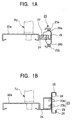
- Figure 1 shows embodiments of an individual-spindle-drive type multiple twister according to the present invention having different mounting aspects for a switching means
- Figure 1A is a schematic side view showing a first embodiment
- Figure 1B is a schematic side view showing a second embodiment.
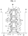
- Figure 2 is a schematic front view showing an embodiment of a two-stage type twister MA that is configured to have the twisting units having the filament yarn supply packages FP disposed in upper and lower stages on both surfaces of the machine body.
- Figure 3 is a schematic side view showing the two-stage type twister MA in Figure 2 as seen from one side.
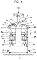
- Figure 4 is a schematic front view showing an embodiment of a one-stage type twister MB that is configured to have the twisting units having the spun yam supply packages SP disposed in one stage on both surfaces of the machine body.
- twisting units TU having the filament yarn supply packages FP are arranged in a line and in upper and lower stages on both surfaces 21a and 21b of a machine body 21.
- the twisting units TU are mounted on a spindle rail 22, and the upper stage twisting units TU are arranged on an upper stage spindle rail 22a at a predetermined interval, while the lower stage twisting units TU are arranged on a lower stage spindle rail 22b at a predetermined interval.
- a switching means 23 corresponding to the spindle drive source 8 for each spindle is provided to drive and stop the spindle drive source 8 for each spindle.
- the switching means 23 are mounted on the upper stage spindle rail 22a at the same or approximately the same height relative to the machine body 21 via bracket members 24 and switch mounting rails 25 located at an appropriate interval.
- the switching means 23 is connected to a motor driving apparatus (not shown in the drawings) located between a two rows of twisting units TU that are disposed back to back.
- the switching means 23 is mounted on the upper stage spindle rail 22a via the switch mounting rail 25, which has a bracket matter 24 and a switch mounting surface 26.
- the switch mounting rail 25 according to the first example is used for both the upper and lower stages and has a switch mounting surface 26a on which an upper stage switch 23a is mounted and a switch mounting surface 26b on which a lower stage switch 23b is mounted.
- the switch mounting surfaces 26a and 26b of the switch mounting rail 25 according to the first example are formed of inclined surfaces that incline toward the machine body 21.
- a vertical section of the switch mounting rail 25 between both inclined surfaces constitutes a switch protection section that protrudes forward from the switch mounting surface 26a.
- a wiring terminal block 27 can be incorporated in the bracket member 24.
- the switching means 23 is mounted on the upper stage spindle rail 22a via the switch mounting rail 25, which has the bracket member 24 and the switch mounting surface 26.
- the switch mounting rail 25 according to the second example is also used for both the upper and lower stages and has a switch mounting surface 26 on which the upper stage switch 23a and the lower stage switches 23b are mounted close to each other.
- the switch mounting rail 25 according to the second example has a switch protection section 28 that protrudes forward from the switch mounting surface 26, and the switch protection section 28 is formed by at least an open space 29 in front of the switch. In the first and second examples, the switch protection section 28 can prevent the operator from inadvertently touching the switching means 23.
- the switching means 23 is located rearward from the front end of the both surfaces 21a and 21b of the machine body 21, and the illustrated embodiments are each configured so that the machine body front end forming member 30 is attached to the bottom of both surfaces 21a and 21b of the machine body 21 in such a way as to protrude toward the working passage side. This configuration can reliably prevent the operator from inadvertently touching the switching means 23.
- each switching means 23 includes a lighting means that is configured to light while the twisting unit TU is stopped, and the lighting means enables the operator to view the stopped twisting units TU from the front of the machine body.
- the one-stage type multiple twister MB comprises a larger number of twisting units TU, having spun yarn supply packages SP, installed in a line on both surfaces 21a and 21b of the machine body 21.
- the twisting units TU for the respective spindles are installed on the spindle rail 22 in a line at a predetermined interval.
- the switching means 23 corresponding to the spindle drive source 8 for each spindle is provided to drive and stop the spindle drive source 8 for each spindle.
- the switching means 23 is mounted at the same or approximately the same height as the upper section of the machine body 21.
- the switching means 23 is also located rearward from the front end of the both surfaces 21a and 21b of the machine body 21, and the illustrated embodiment is configured so that the machine body front end forming matter 30 is attached to the bottom of both surfaces 21a and 21b of the machine body 21 in such a way as to protrude toward the working passage side.
- each switching means 23 includes a lighting means that is configured to light while the twisting units TU is stopped. This lighting means enables the operator to view the stopped twisting unit TU from the front of the machine body 21.
- the spindle can be driven and stopped for each twisting unit TU, and even given the large number of switches along the machine body, the drive conditions of the spindles can be checked visually and promptly based on the lighting conditions of the switches. In particular, even if a certain spindle is stopped due to a malfunction in the spindle motor or its drive circuit, its spindle position can be promptly identified so as to take required action.
- the switch mounting rail is mounted on the spindle rail using brackets located at an appropriate interval, so a wiring terminal block can be provided on the bracket to join together wires from a plurality of switches in order to facilitate wiring and maintenance (mounting and removal).
- the inclined sections are formed on both upper and lower sides of the mounting rail, and the switches for the upper and lower side respectively are provided on the inclined sections in such a way as to protrude therefrom. Consequently, a switch can be simply operated.
- This configuration is effective during yarn threading operations. In threading operations, yarn that has been passed through the spindle is drawn up and passed through the guide roller and feed roller, a small length of the yarn is subsequently wound around a bobbin held on the cradle, and the switch is then turned on with a predetermined timing to start winding (The cradle is lowered to contact the take-up tube with the winding drum).
- a motor end ME and a control box CB are connected to one side MA-a of the machine body MA, and a gear end GE that performs a change pulley operation (changing the count of twist to change the ratio between the rotation speed of the rotating disc and the rotation speed of the winding drum) is connected to the other side MA-b of the machine body MA.
- the gear end GE, the motor end ME, and the control box CB are connected to one side MB-a of a machine body MB, and a return pulley RP used to install a tangential belt for simultaneously driving the spindles is connected to the other side MB-b of the machine body MB.
- the motor for driving both the tangential belt and the winding apparatus occupies most of the inside of the motor end ME, and the motor for adjusting the tension of the belt may move and requires space for its movement.
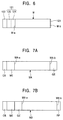
- the conventional simultaneous drive type multiple twister requires a space in the longitudinal direction of each machine body as shown in Figure 7A and 7B.
- An object of the present invention is thus to provide an individual-spindle-drive type multiple twister that includes a drive motor for each spindle, wherein the drive chamber and control chamber are compact and concentrated on one side of the machine body so as to enable various change operations to be performed easily.
- the present invention provides an individual-spindle-drive type multiple twister that includes a spindle drive motor for each spindle and that drives a winding drum and a traverse using a common winding system motor, wherein:
- the present invention provides an individual-spindle-drive type multiple twister wherein the transmission means is provided at a position at which it does not appear to overlap the winding system motor as seen from the direction in which the first and second chambers appear to overlap each other.
- the present invention provides an individual-spindle-drive type multiple twister wherein the second chamber includes a speed reducer for reducing the speed of the rotational drive of the winding system motor and a transmission means for transmitting the rotational drive of the output shaft of the speed reducer to the winding drum shaft.
- Figure 6 is a schematic plane view showing an example of a basic configuration of the individual-spindle-drive type multiple twister according to the present invention.
- Figure 7 shows an example of a configuration of a conventional simultaneous drive type multiple twister
- Figure 7A is a schematic plane view showing an example of an apparatus for a filament yarn
- Figure 7B is a schematic plane view showing an example of an apparatus for a spun yarn.
- Figure 8 is a schematic front view that shows the details of an example of specific configuration that is applied to an individual-spindle-drive type multiple twister with upper and lower stages according to the present invention.
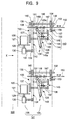
- Figure 9 is a schematic front view showing the details of a specific embodiment of a winding system driving mechanism according to the configuration example shown in Figure 8, and
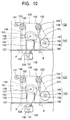
- Figure 10 is a schematic side view as seen from the direction of arrow X shown in Figure 9.
- a winding system drive chamber 121 is provided on one side M-a of a machine body M, and a control box 122 is coupled to the winding system drive chanter 121.
- the other side M-b of the machine body M is composed of only a machine body cover 123.
- the winding system drive chamber 121 is partitioned midway using a partitioning plate, and the drive chamber 121 therfore consists of a first chamber 124 and a second chamber 125 located across the partitioning plate.
- the partitioning plate supports a plurality of shafts, including such as a winding drum shaft 132 which is described below, a drive shaft 136, and a cam operating shaft 147 in such a way as to protrude from the first chamber 124 toward the second chamber 125.
- the partitioning plate acts as a supporting member for supporting a plurality of drive transmission shafts (the winding drum shaft 132, the drive shaft 136, the cam operating shaft 147, and so on) that transmit the drive of a winding system motor 126 to each section.
- the partitioning plate defines the first chamber 124 and the second chamber 125, but the sizes of the spaces in both chambers as determined by the position of partitioning plate are not particularly limited in any way.
- the winding system drive chamber 126 is accommodated in the second chamber 125 of the winding system drive chamber 121 in such a way as to be fixed to a frame 127, and a traverse mechanism section 128 is accommodated in the first chamber 124 of the winding system drive chamber 121.
- a speed reducer 130 comprising an output shaft 131 is connected to the output shaft 129 side of the winding system motor 126.
- the second chamber 125 of the winding system drive chamber 121 accommodates a first transmission means 133 for transmitting the rotational drive transmitted from a winding drum shaft 132 that extends to a winding drum 115 in the machine body M to the traverse mechanism section 128, and a second transmission means 134 for transmitting the rotational drive of the output shaft 131 of the speed reducer 130 to the winding drum shaft 132.
- the first transmission means 133 comprises a pulley 135 provided on the winding drum shaft 132, a pulley 137 provided on the drive shaft 136 of the traverse mechanism section 128, and a belt 138 that runs between the pulley 135 and the pulley 137.
- the second transmission means 134 comprises a pulley 139 provided on the output shaft 131 of the speed reducer 130, pulleys 140, 140 provided on the winding drum shafts 132, 132, an adjustment pulley 141, and a belt 142 that runs between these pulleys.
- the first transmission means 133 is assembled at a position where it does not appear to overlap the winding system motor 126 as seen from the direction (the arrow X direction in Figure 9) in which the first chamber 124 and the second chamber 125 appear to overlap each other.
- the traverse mechanism section 128 includes a cam member 148 mounted on a cam operation shaft 147 that is rotationally driven relative to the drive shaft 136 by a third transmission means 143, which comprises pulleys 144 and 145 and a belt 146.
- the cam member 148 is a disc-shaped cam that is fixed to the cam operation shaft 147 in such a way as to incline relative to the axis of the shaft 147.
- the traverse mechanism section 128 includes an oscillating lever member 149 that is oscillated by the rotational drive of the cam member 148.
- the oscillating lever member 149 is pivotably supported on the frame 127 by a pivotal shaft P provided at one end 149a, and its other end 149b is connected to a traverse guide 150.
- the oscillating lever 149 comprises an engaging piece 151 that engages a surface 148a of the cam member 148 and that comprises a spring 152 that urges the oscillating lever member 149 in the direction in which it is pulled.
- the pair of oscillating lever members 149, 149 on both sides engage the single cam member 148, and the springs 152, 152 are connected to the pair of oscillating lever members 149, 149, respectively.
- One end of each of the pair of springs 152, 152 is connected to a common chain (not shown in the drawing) so that the pair of oscillating lever members 149, 149 oscillate concurrently.
- the traverse mechanism section 128 configured as described above transforms the rotational drive transmitted from the winding drum shaft 132 into the reciprocating motion of the traverse guide 150. That is, the rotational drive of the winding drum shaft 132 is transmitted to the cam member 148 via the first transmission means 133 and the third transmission means 143 to rotate the cam member 148 and oscillate the oscillating lever member 149 engaged with the cam member 148, thereby enabling the traverse guide 150 connected to the operation end side of the oscillating lever member 149 to be reciprocated in the lateral direction shown by the arrow in Figure 9.
- a fourth transmission means 153 comprising pulleys 154 and 155 and a belt 156 transmits the rotational drive of the winding drum shaft 132 to a feed roller shaft 157.
- the two-stage type twister MA comprises a large number of twisting units TU including filament yarn supply packages FP installed in a line on both surfaces of the machine body.
- the twisting unit TU for each spindle is mounted on a spindle rail SR, and the upper stage twisting units TU are arranged on an upper stage spindle rail SR1 at a predetermined interval, while the lower stage twisting units TU are arranged on a lower stage spindle rail SR2 at a predetermined interval.
- a switching means SM corresponding to a spindle drive source 108 for each spindle is provided to drive and stop the spindle drive source for each spindle.
- the switching means SM are mounted on the upper stage spindle rail SR1 at the same or approximately the same height relative to the machine body 21 via bracket members and switch mounting rails located at an appropriate interval.
- Each switching means SM includes a lighting means that is configured to light while the twisting units TU is stopped, thereby enabling the operator to view the stopped twisting unit TU from the front of the machine body.
- the first transmission means 133 and the second transmission means 134 which sometimes require various adjustments and modifications, are located closer to the winding system motor 126 than the supporting section for the driving transmission shaft, which is located midway inside the winding system drive chamber 121. Consequently, the transmission means can be adjusted or changed using the space (second chamber 125) on the winding system motor 126 side defined by the supporting section.
- the winding system drive motor may be small. Consequently, the winding system drive motor is located in the second chamber in which the traverse mechanism section is not provided, and the first transmission means for this motor is also located in the second chamber. As a result, the space in the second chamber can be used to adjust the first transmission means in order to change the traverse angle.
- the first transmission means is configured so as not to appear to overlap the winding system motor as seen from the direction in which the first and second chamber appear to overlap each other.
- the drive chamber can be compact, enabling the traverse angle change operation to be performed more easily.
- the space in the second chamber can be used to adjust the second transmission means in order to change the number of twists imparted to the yarn more easily.
Landscapes
- Engineering & Computer Science (AREA)
- Mechanical Engineering (AREA)
- Textile Engineering (AREA)
- Spinning Or Twisting Of Yarns (AREA)
Applications Claiming Priority (4)
| Application Number | Priority Date | Filing Date | Title |
|---|---|---|---|
| JP10228953A JP2000064132A (ja) | 1998-08-13 | 1998-08-13 | 単錘駆動型多重撚糸機 |
| JP22887798 | 1998-08-13 | ||
| JP22895398 | 1998-08-13 | ||
| JP22887798A JP3301389B2 (ja) | 1998-08-13 | 1998-08-13 | 単錘駆動型多重撚糸機 |
Publications (2)
| Publication Number | Publication Date |
|---|---|
| EP0979889A2 true EP0979889A2 (de) | 2000-02-16 |
| EP0979889A3 EP0979889A3 (de) | 2001-05-16 |
Family
ID=26528505
Family Applications (1)
| Application Number | Title | Priority Date | Filing Date |
|---|---|---|---|
| EP99108783A Withdrawn EP0979889A3 (de) | 1998-08-13 | 1999-05-03 | Mehrfachdraht-Zwirnmaschine mit Einzelspindelantrieb |
Country Status (3)
| Country | Link |
|---|---|
| US (1) | US6167688B1 (de) |
| EP (1) | EP0979889A3 (de) |
| CN (1) | CN1284891C (de) |
Families Citing this family (5)
| Publication number | Priority date | Publication date | Assignee | Title |
|---|---|---|---|---|
| US7260914B2 (en) * | 2003-12-27 | 2007-08-28 | Floral Transport Systems, Llc | Method and apparatus for packaging horticultural products |
| US20050138862A1 (en) * | 2003-12-27 | 2005-06-30 | O'connor Jeremiah | Method and apparatus for packaging horticultural products |
| CN106087144B (zh) * | 2016-07-29 | 2018-07-24 | 浙江天竺纺机有限公司 | 一种纱线的加捻装置 |
| CN108796686A (zh) * | 2017-05-02 | 2018-11-13 | 无锡祥虹工贸有限责任公司 | 一种捻线机用打线机构 |
| CN110438614B (zh) * | 2019-08-19 | 2020-09-29 | 徐州华运纺织有限公司 | 一种结构稳定的混纺纱生产用设备 |
Family Cites Families (9)
| Publication number | Priority date | Publication date | Assignee | Title |
|---|---|---|---|---|
| US3823540A (en) * | 1972-09-13 | 1974-07-16 | Rieter Ag Maschf | Brake for spinning and twisting spindles |
| DE2946031A1 (de) * | 1979-11-14 | 1981-05-21 | Zinser Textilmaschinen Gmbh, 7333 Ebersbach | Vorrichtung zum abschalten eines elektromotorischen einzelspindelantriebes bei betriebsstoerung an einer textilmaschine |
| DE3619647A1 (de) * | 1986-06-11 | 1987-12-17 | Zinser Textilmaschinen Gmbh | Verfahren und vorrichtung zum einzelmotorischen antrieb einer spindel bei einer spinnmaschine |
| DE3727939A1 (de) | 1987-08-21 | 1989-03-02 | Skf Textilmasch Komponenten | Schaltungsanordnung fuer textilmaschinen, insbesondere spinnmaschinen mit einzelmotorantrieb der spindeln |
| DE3822420A1 (de) * | 1988-07-02 | 1990-01-04 | Skf Textilmasch Komponenten | Ringspinn-/oder ringzwirnmaschine |
| DE3912370A1 (de) * | 1989-04-14 | 1990-10-18 | Novibra Gmbh | Textilmaschine, insbesondere spinn- oder zwirnmaschine |
| DE4106953A1 (de) * | 1991-03-05 | 1992-09-10 | Stahlecker Fritz | Elektromotorischer einzelantrieb fuer eine spinn- oder zwirnspindel mit einem elektromotor |
| DE4424349C2 (de) * | 1994-07-11 | 1996-10-24 | Zinser Textilmaschinen Gmbh | Einzelmotorischer Antrieb für eine Spinn- oder Zwirnspindel |
| EP0806501A3 (de) * | 1996-05-11 | 1998-11-11 | Motonobu Hattori | Spinnmaschine mit Steuersystem für Spindelmotoren |
-
1999
- 1999-04-28 US US09/301,017 patent/US6167688B1/en not_active Expired - Fee Related
- 1999-05-03 EP EP99108783A patent/EP0979889A3/de not_active Withdrawn
- 1999-08-04 CN CN99111306.3A patent/CN1284891C/zh not_active Expired - Fee Related
Also Published As
| Publication number | Publication date |
|---|---|
| CN1284891C (zh) | 2006-11-15 |
| CN1245227A (zh) | 2000-02-23 |
| US6167688B1 (en) | 2001-01-02 |
| EP0979889A3 (de) | 2001-05-16 |
Similar Documents
| Publication | Publication Date | Title |
|---|---|---|
| US5509261A (en) | Stepping motor arrangement for driving a silver feed roller in a rotor spinning machine | |
| KR100474600B1 (ko) | 개별 방추 구동형 섬유 기계 | |
| US6167688B1 (en) | Individual-spindle-drive type multiple twister | |
| US4332129A (en) | Multi-spindle double twist twisting machine | |
| TWI713816B (zh) | 假撚加工機 | |
| US20110094203A1 (en) | Twisting machine capable of independently controlling twisting speed and winding speed and method of same | |
| EP0473134B1 (de) | Automatische Spulenwechselvorrichtung von einer Wickelmaschine | |
| US7392648B2 (en) | Rotor Spinning machine | |
| TWI822994B (zh) | 假撚加工機 | |
| CN100494028C (zh) | 用于生产交叉卷绕筒子的纺织机的卷绕装置的纱线横动装置 | |
| KR20000017237A (ko) | 단일 추 구동형 다중 연사기 | |
| JP2007112625A (ja) | 繊維機械用巻取り装置 | |
| CN214243275U (zh) | 一种摇纱机送纱张力调整机构 | |
| US3981130A (en) | Single process twisting machine for producing twisted yarn from two strands | |
| KR200293248Y1 (ko) | 투포원 연사기의 전자구동 시스템 및 그 구동제어방법 | |
| JP3235564B2 (ja) | 単錘駆動型多重撚糸機 | |
| JP3301389B2 (ja) | 単錘駆動型多重撚糸機 | |
| US5551222A (en) | Driving apparatus for two-for-one twister having advantageously located speed change devices | |
| EP0612683B1 (de) | Aufwickelmaschine für viele fäden | |
| CN100497144C (zh) | 纺织机械 | |
| CN111088568B (zh) | 横动装置、牵伸装置以及纺纱机 | |
| US4418522A (en) | Knockoff control system and apparatus for textile strand twist frames | |
| KR100486039B1 (ko) | 투포원 연사기의 전자구동 시스템 및 그 구동제어방법 | |
| JPH11263533A (ja) | 巻取機のリボン巻防止装置 | |
| JP3235561B2 (ja) | 単錘駆動型繊維機械の制御システム |
Legal Events
| Date | Code | Title | Description |
|---|---|---|---|
| PUAI | Public reference made under article 153(3) epc to a published international application that has entered the european phase |
Free format text: ORIGINAL CODE: 0009012 |
|
| AK | Designated contracting states |
Kind code of ref document: A2 Designated state(s): AT BE CH CY DE DK ES FI FR GB GR IE IT LI LU MC NL PT SE |
|
| AX | Request for extension of the european patent |
Free format text: AL;LT;LV;MK;RO;SI |
|
| PUAL | Search report despatched |
Free format text: ORIGINAL CODE: 0009013 |
|
| AK | Designated contracting states |
Kind code of ref document: A3 Designated state(s): AT BE CH CY DE DK ES FI FR GB GR IE IT LI LU MC NL PT SE |
|
| AX | Request for extension of the european patent |
Free format text: AL;LT;LV;MK;RO;SI |
|
| STAA | Information on the status of an ep patent application or granted ep patent |
Free format text: STATUS: THE APPLICATION HAS BEEN WITHDRAWN |
|
| 18W | Application withdrawn |
Withdrawal date: 20010508 |