EP0979911A2 - Höhenverstellbare Bodenfläche - Google Patents
Höhenverstellbare Bodenfläche Download PDFInfo
- Publication number
- EP0979911A2 EP0979911A2 EP99115378A EP99115378A EP0979911A2 EP 0979911 A2 EP0979911 A2 EP 0979911A2 EP 99115378 A EP99115378 A EP 99115378A EP 99115378 A EP99115378 A EP 99115378A EP 0979911 A2 EP0979911 A2 EP 0979911A2
- Authority
- EP
- European Patent Office
- Prior art keywords
- platforms
- height
- mobile
- hoists
- lifting
- Prior art date
- Legal status (The legal status is an assumption and is not a legal conclusion. Google has not performed a legal analysis and makes no representation as to the accuracy of the status listed.)
- Withdrawn
Links
- 239000002131 composite material Substances 0.000 claims description 20
- 230000006870 function Effects 0.000 claims description 10
- 238000006243 chemical reaction Methods 0.000 claims description 7
- 238000010276 construction Methods 0.000 claims description 6
- 230000000284 resting effect Effects 0.000 claims description 6
- 238000009434 installation Methods 0.000 claims description 5
- 238000013459 approach Methods 0.000 claims description 4
- 230000008878 coupling Effects 0.000 claims description 4
- 238000010168 coupling process Methods 0.000 claims description 4
- 238000005859 coupling reaction Methods 0.000 claims description 4
- 230000000694 effects Effects 0.000 claims description 4
- 238000001514 detection method Methods 0.000 claims description 3
- 238000009826 distribution Methods 0.000 claims description 3
- 238000003860 storage Methods 0.000 claims description 3
- 230000004913 activation Effects 0.000 claims description 2
- 238000000034 method Methods 0.000 claims description 2
- 230000008569 process Effects 0.000 claims description 2
- 238000012545 processing Methods 0.000 claims description 2
- 230000000630 rising effect Effects 0.000 claims description 2
- 230000001360 synchronised effect Effects 0.000 claims description 2
- 235000004443 Ricinus communis Nutrition 0.000 claims 1
- 240000000528 Ricinus communis Species 0.000 claims 1
- 230000005693 optoelectronics Effects 0.000 claims 1
- 230000001105 regulatory effect Effects 0.000 claims 1
- 230000007246 mechanism Effects 0.000 description 12
- 238000013461 design Methods 0.000 description 10
- 230000008901 benefit Effects 0.000 description 7
- 238000012544 monitoring process Methods 0.000 description 4
- 230000008859 change Effects 0.000 description 3
- 238000005516 engineering process Methods 0.000 description 3
- 238000012423 maintenance Methods 0.000 description 3
- 150000001875 compounds Chemical class 0.000 description 2
- 238000005034 decoration Methods 0.000 description 2
- 238000006073 displacement reaction Methods 0.000 description 2
- 238000005259 measurement Methods 0.000 description 2
- 230000009471 action Effects 0.000 description 1
- 238000009412 basement excavation Methods 0.000 description 1
- 230000000295 complement effect Effects 0.000 description 1
- 230000003247 decreasing effect Effects 0.000 description 1
- 238000007689 inspection Methods 0.000 description 1
- 230000010354 integration Effects 0.000 description 1
- 239000002655 kraft paper Substances 0.000 description 1
- 238000004519 manufacturing process Methods 0.000 description 1
- 239000003550 marker Substances 0.000 description 1
- 230000003287 optical effect Effects 0.000 description 1
- 210000000056 organ Anatomy 0.000 description 1
- 230000003068 static effect Effects 0.000 description 1
- 238000012549 training Methods 0.000 description 1
- 238000011144 upstream manufacturing Methods 0.000 description 1
- 230000000007 visual effect Effects 0.000 description 1
Images


Classifications
-
- B—PERFORMING OPERATIONS; TRANSPORTING
- B66—HOISTING; LIFTING; HAULING
- B66F—HOISTING, LIFTING, HAULING OR PUSHING, NOT OTHERWISE PROVIDED FOR, e.g. DEVICES WHICH APPLY A LIFTING OR PUSHING FORCE DIRECTLY TO THE SURFACE OF A LOAD
- B66F11/00—Lifting devices specially adapted for particular uses not otherwise provided for
- B66F11/04—Lifting devices specially adapted for particular uses not otherwise provided for for movable platforms or cabins, e.g. on vehicles, permitting workmen to place themselves in any desired position for carrying out required operations
-
- B—PERFORMING OPERATIONS; TRANSPORTING
- B66—HOISTING; LIFTING; HAULING
- B66F—HOISTING, LIFTING, HAULING OR PUSHING, NOT OTHERWISE PROVIDED FOR, e.g. DEVICES WHICH APPLY A LIFTING OR PUSHING FORCE DIRECTLY TO THE SURFACE OF A LOAD
- B66F7/00—Lifting frames, e.g. for lifting vehicles; Platform lifts
-
- E—FIXED CONSTRUCTIONS
- E04—BUILDING
- E04G—SCAFFOLDING; FORMS; SHUTTERING; BUILDING IMPLEMENTS OR AIDS, OR THEIR USE; HANDLING BUILDING MATERIALS ON THE SITE; REPAIRING, BREAKING-UP OR OTHER WORK ON EXISTING BUILDINGS
- E04G1/00—Scaffolds primarily resting on the ground
- E04G1/18—Scaffolds primarily resting on the ground adjustable in height
- E04G1/22—Scaffolds having a platform on an extensible substructure, e.g. of telescopic type or with lazy-tongs mechanism
-
- E—FIXED CONSTRUCTIONS
- E04—BUILDING
- E04H—BUILDINGS OR LIKE STRUCTURES FOR PARTICULAR PURPOSES; SWIMMING OR SPLASH BATHS OR POOLS; MASTS; FENCING; TENTS OR CANOPIES, IN GENERAL
- E04H3/00—Buildings or groups of buildings for public or similar purposes; Institutions, e.g. infirmaries or prisons
- E04H3/10—Buildings or groups of buildings for public or similar purposes; Institutions, e.g. infirmaries or prisons for meetings, entertainments, or sports
- E04H3/12—Tribunes, grandstands or terraces for spectators
- E04H3/126—Foldable, retractable or tiltable tribunes
-
- E—FIXED CONSTRUCTIONS
- E04—BUILDING
- E04H—BUILDINGS OR LIKE STRUCTURES FOR PARTICULAR PURPOSES; SWIMMING OR SPLASH BATHS OR POOLS; MASTS; FENCING; TENTS OR CANOPIES, IN GENERAL
- E04H3/00—Buildings or groups of buildings for public or similar purposes; Institutions, e.g. infirmaries or prisons
- E04H3/10—Buildings or groups of buildings for public or similar purposes; Institutions, e.g. infirmaries or prisons for meetings, entertainments, or sports
- E04H3/22—Theatres; Concert halls; Studios for broadcasting, cinematography, television or similar purposes
- E04H3/24—Constructional features of stages
- E04H3/26—Revolving stages; Stages able to be lowered
Definitions
- Height-adjustable shelves are already known single or several next to each other lying platforms exist and each one or even several lifting devices assigned to them and their Drive devices need. Will be great for Floor areas a variety of such individually adjustable platforms, results from this inferring the same number of expensive Kraft.- or hand-operated actuators and drive units, as well as their assigned control and safety-related Facilities. As a result, in addition to the high Manufacturing and assembly costs as well as maintenance expenses very high. Also the need for large ones required Amounts of energy with the associated high From an economic perspective, providing energy is not sensible.
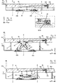
- the instantaneous conversion of a floor area using a larger number of individually height-adjustable platforms with a singular or relative to the number of platforms lower number of hoists and drive machines and the hoists and platforms like that to design that the hoists are not each at one Platform are bound, but relative to the platforms are mobile, and the platforms and hoists for the purpose the conversion is currently merged, and after one the platforms were converted using support devices supported, and the hoists again from the Platforms are solved, and for subsequent adjustment other platforms can be used.
- the one motor mobile hoist includes which in a basement is arranged below several platforms and in one horizontal travel axis can be moved under the platforms and a vertical stroke axis is controllable.
- the hoist including the chassis because of the platforms that obstruct the view by an operator who is during the operation must stay below the platforms in the machine room below the load center of the individual platforms by Visual contact can be placed, which makes it even more difficult is due to the fact that the drive system is lacking Brake device a certain even when it is switched off Has caster.
- An exact placement and posture of the Hoist could even when using a brake Locking the wheels will not result, as ever according to the speed and weight of the mobile The hoist cannot rule out sliding or slipping is.
- the support devices not permanently with one as before the structure supporting the platforms are anchored, but the platforms P, by means of a height adjustment portable or positionally movable support devices S, are supported, and the support devices do not like have so far been permanently installed in a basement and the top end of which is not fixed below one built-in floor, but the support devices S, and their arrangement are designed in such a way that these with their platforms P, facing Stop S10, over the top F10, one of the Platforms P, surrounding floor F1, can protrude or can be carried out, or the support devices S, with their respective platforms P, facing Stop S10, over the top P10, from neighboring platforms P, protrude, or out can be performed.
- the support devices S are preferably not made of known from DE 25 45 074, permanent and rigid with one Structure connected, but are portable, or changeable, i.e. They are used to support the Platforms P, to these, or their arrangement area guided, or are movable with the platforms P ,. connected and carried by the platforms P, and with the platforms P, with.
- both sideways outside of the platforms, as well as below the Platforms can be arranged. It is particularly advantageous the support devices S, preferably in a new arrangement to be placed below the platforms P, and in the manner to design that the same does not have the outer End faces P11, the platforms P, protrude, whereby several platforms P, with their outer end faces P11, even immediately after two or more outer sides are lined up, and between the platforms P, no annoying protrusions or larger Spaces arise, but the platforms P, with lateral distances a few millimeters, or directly built up against each other, or strung together can.
- Another advantage of the invention is that due to the movable support devices S, the platforms P, both mobile, as well as stationary or localized within of a building can be arranged, and at one Distance of the platforms P, none from their place of operation open pit or basement, or permanently with a floor F1, or structure firmly anchored and obstructing supports remain. For example, it is possible that in Buildings that do not have sufficient installation space inside their surrounding walls or their permanently installed Floor space for the integration of the platforms P, have, or a sports floor is present, which none Joints may have that the platforms P, (Fig.
- Platforms P during their height adjustment to the mobile Hoists H, tied up and fixed against them the mobile hoists H, by means of vertically acting Management bodies take on the management function, and the Platforms P, by means of the fixing elements P3, against the mobile hoists H, are fixed out, and a side Move platforms P relative to their surroundings or to the mobile hoists H is prevented.
- the platforms P, and a die Platforms P immediately surrounding structure F1, or dormant structure organs and facilities for management and spacing, e.g. Sliders or Slide rails, or rollers for guidance and spacing are classified.
- the mobile hoists H both from the outside P11, the Platforms P, or from the tops P10, of the platforms P, can be brought up to this. So it is e.g. in some structures not possible below the platforms Machine rooms or travel areas for the mobile hoists ready to deploy or bring in so that a feeder or coupling the mobile hoists to the platforms only possible from the outside or the top is. In most cases, however, it is desirable that the mobile hoists H, arranged below the platforms P. are.
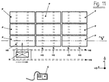
- the mobile hoists H are fed precisely to the Platforms P to ensure are the mobile hoists H, preferably in guideways H5, which are below the platforms P, extend.
- the guideways H5, in their length are dimensioned so that they over the Arrangement area of the platforms P, lead out, and the mobile hoists H, in one of the platforms P, not overlaid area F4, can be guided, and in this area is accessible to maintenance personnel and the like are.
- Another advantage of the arrangement area of the Platforms P, extended guideways H5, is the possibility (Fig.
- Interlocks H10 with mutually interlocking preferably conical guide surfaces are provided, that the mobile hoists H, during a Locking in an exact and in the same place repeatable position relative to the platforms set up automatically, and temporarily, quasi stationary with a resting structure or a Foundation floor F2, or the guideway H5, are connected.
- holding positions are arranged along the travel route and assigned to the arrangement areas of the platforms P and assigned to the position of the platforms P.
- These stop positions are preferably marked by means of mechanical, electrical or electronic position marks C1, and monitored by a controller C, it being possible for position-giving switch contacts or proximity switches and the like to be assigned to each stop position, or the route is detected by means of electronic path measurement, and the The length of the route is subdivided into individual stops in the form of optical or magnetic scales and the mobile hoists each lead past the scalings and their current driving position is continuously recorded, and with the help of a higher-level control device C, the mobile hoists into the respective platforms assigned and controlled scaling area, and come to a standstill automatically in this.
- the length of the route is recorded with other contactless measuring devices, for example with a laser beam, which enables a distance measurement relative to a reference point.
- the travel drives of the mobile hoists H can not only be driven at one speed as before, but that the driving speed can be varied step-wise or continuously, which means that longer distances with greater speed (rapid travel ) are put back, and when approaching a target point or stopping position the speed is reduced and the last part of the journey to a target position or stopping position takes place at a greatly reduced speed relative to the rapid traverse, as a result of which the mobile hoists H become more dynamic as a result Force forces more precisely into their target positions or working positions and have them stopped, and an unwanted overrun of the working positions or target positions relative to the platforms P can be excluded.
- the mobile hoists H are driven with traction motors and the traction motors have a step-by-step or continuously variable speed.
- Another advantage of the position markings C1 along the route is that the mobile hoists H are no longer controlled in their working positions by eye and hand command, as in DE 25 45 074, but the mobile hoists H are automatically in their respective working positions are controlled relative to the platforms P, and the control device C (FIGS. 1, 3, 11) can also be arranged above the platforms P or outside the machine rooms, and the operator during the height adjustments from outside or above the machine rooms can control the mobile hoists H,.
- the control device for command and control the mobile hoist H is preferably a so-called Computer control C, which has a data memory and a electronic data processing unit, and a keyboard for entering control commands or in addition to Retrieval of programmed control commands.
- Computer control C which has a data memory and a electronic data processing unit, and a keyboard for entering control commands or in addition to Retrieval of programmed control commands.
- the platforms P can be raised or lowered done according to the invention in different ways.
- the mobile hoists H by means of stop elements or Articulation elements on the movable support devices S, attack and link them and straighten them up or lower while the movable supports in turn link and carry the platforms.
- the platforms P are preferably facing Stop sides of the mobile hoists H, and the mobile ones Hoists H, facing stop sides of platforms P, with stop and fixation elements P3, which in mutual approximation, so that these interacting in pairs under constant Approach and subsequent contact horizontally positive, or almost positive Establish contact.
- the fixation members are preferably P3, with conical or spherical guide surfaces and Provide stop surfaces, which are in pairs in one another lead or grab, and the platforms P, relative to the mobile hoists H, automatic or always in a reproducible, aligned one the same assignment to each other.
- This new solution has the particular advantage that maximum only as many power-operated actuators H8 are required become, like a platform P, or support device S, Locks S7, has, and is therefore on the one hand the number is particularly economical and secondly possible sources of error or sources of interference are reduced.
- This advantageous measure does not, as in DE 25 45 074 described only a hoist with a Shown lifting drive, but the mobile hoists H, carry and carry additional actuators H8, or actuators to set up the Support devices S, and for actuating the locks S7, with itself, and their functions are not just for that Raising or lowering the platforms P, provided, but equipped to perform multiple functions, and to multi-functional mobile lifting robots.
- This configuration is particularly advantageous in connection with the computer control C, since now in a new way, the entire structure of a height-adjustable floor area can be done fully automatically, and the driving movements and lifting or lowering and setting up and Locking or unlocking the support devices S, can be done programmatically, after which the mobile hoists H, trained as a robot, all to build up the floor area can perform the required operations independently.
- the function monitoring or end position monitoring of the Locking S7 preferably does not take place as in conventional platforms directly through control bodies, which are permanently connected to the platforms P, but these are in a new way (without drawing) also with the mobile hoists H, or on the mobile ones Hoists H, with guided, and to the platforms P, or Support devices S, and their interlocks S7 guided.
- the mobile hoists H preferably in a flat design are carried out, the lifting forces of lifting drives, preferably hydraulically powered lifting cylinders H9, by means of of the lift cylinders H9, articulated tilt adjustable Lifting arms H, on platforms P; be transferred, whereby the inclinable lifting arms H, one Scissor structures, a so-called lifting scissors put together which are flat together in a lower operating state placed below the platforms P, only a small one Need installation height. It is necessary that the Lifting arms H, especially when driving completely or almost completely parallel to each other are aligned.
- auxiliary linkages H11 or auxiliary lifting devices
- auxiliary linkages H11 steeper in its inclination position and in hers
- the effective lengths are shorter than the lifting arms H4, the lifting scissors.
- auxiliary links H11 are from the Several types of auxiliary lifting devices have been used in the past known for flat-construction lifting scissors. So there is e.g.
- Lifting wedges that initially engage the lifting arms, or rotatable or swiveling link levers, which the Link the lifting arms from their lowest position and support, or cam rollers, which between the Scissor arms an ever-widening wedge mouth form, or in addition to the main stroke drive upstream short-stroke drives or pressure elements.
- lifting bags or lifting bellows which squeeze flat in the rest position, or lay together and expand with a pressure medium, and thus cause an increase.
- Auxiliary lifting devices are tried and tested in practice consequently for lifting the lifting arms from the lowest Position usable out. Thereby lose with increasing Erection of the lifting arms of the auxiliary lifting devices Effect and the articulation of the lifting arms is now directly from the drive elements of the main lifting phase.
- the composite bars P5 are preferably (FIGS. 8, 9, 10). permanently connected to the platforms P, and become the Purpose of their activation via the outer end faces P11, the platforms P, led out and into the outer End face P11, the adjacent platform P, led into it. It is in the spirit of the invention provided that the actuation of the composite latch P5, both manually, as well as in a preferred embodiment power-fed and remote-controlled actuators H, e.g. Actuators, or actuating cylinder H7, and the like. he follows.
- actuators H7, for Compound bar P5, arranged on the mobile hoists H. and from these to platforms P or Composite ledger P5, brought up and by means of Control device C, are commanded and controlled, so that according to the invention sought several times functional robot function the mobile hoists H to a additional functions have been added or expanded.
Landscapes
- Engineering & Computer Science (AREA)
- Architecture (AREA)
- Structural Engineering (AREA)
- Civil Engineering (AREA)
- Mechanical Engineering (AREA)
- Life Sciences & Earth Sciences (AREA)
- Geology (AREA)
- Multimedia (AREA)
- Floor Finish (AREA)
- Conveying And Assembling Of Building Elements In Situ (AREA)
Abstract
Description
Ein weiterer Vorzug der Positionsmarkierungen C1, entlang der Fahrstrecke ist es, daß die mobilen Hubwerke H, nicht mehr wie in der DE 25 45 074 per Augenmaß und Handbefehl, in ihre Arbeitspositionen gesteuert werden, sondern die mobilen Hubwerke H, automatisch in ihre jeweiligen Arbeitspositionen relativ zu den Plattformen P, gesteuert sind, und die Steuerungseinrichtung C, (Fig. 1,3,11) auch oberhalb der Plattformen P, bzw. außerhalb der Maschinenräume angeordnet werden kann, und die Bedienperson während der Höhenverstellungen von außerhalb oder oberhalb der Maschinenräume die Steuerung der mobilen Hubwerke H, vollziehen kann.
- C
- Steuerungseinrichtung
- C1
- Positionsmarkierungen
- F
- Fußbodenfläche
- F1
- Festboden / Oberboden
- F2
- Festboden / Fundamentboden / Fundament
- F10
- Oberseite Fußboden
- H
- Mobile Hubwerke
- H1
- Hubhöhe der Plattformen /Nutzhub
- H2
- Bauhöhe der Plattformen
- H3
- Tiefenmaß einer Grube
- H4
- Zwischenraum zwischen zwei Plattformen oder einem Festboden
- H5
- Fahrweg / Führungsbahn Y
- H6
- Fahrweg / Führungsbahn X
- H7
- Betätigungsorgan für Verbundriegel P5
- H8
- Betätigungsorgan für Einrichtung und Verriegelung der Stützen S,
- H9
- Hebeantrieb für Hubwerk H/ Hydraulikzylinder
- H10
- Verriegelung von Hubwerk zu Fundament
- H11
- Hilfshubeinrichtung für Hubwerk H
- P
- höhenverstellbare Plattformen
- P2
- Stapelung von Plattformen
- P3
- Fixiereinrichtung zwischen Plattformen P, und Hubwerken H
- P4
- Halteeinrichtung / Verriegelung zwischen Plattformen P und Hubwerken H
- P5
- Verbundriegel / Mitnehmer zwischen mehreren Plattformen
- S
- Stützeinrichtungen
- S1
- Steckbare Säulenstütze
- S2
- Versenkbare Säulenstütze
- S3
- Mehrbeiniger Stützbock
- S4
- Schwenkstütze
- S5
- Scherenstütze x-förmig
- S6
- Scherenstütze Y-förmig
- S7
- Verriegelung für Stützeinrichtungen / Plattformen
Claims (18)
- Höhenverstellbare Bodenfläche für Mehrzweckbauten und dergleichen, die zu ihrer Umwandlung in eine höher,- oder tiefer gelegene Ebene, z.B. Bühne oder Galerie, oder Steg, oder Versenkung und dergleichen oder zur Umwandlung in eine stufenweise steigende oder fallende Tribühne, aus mehreren individuell höhenverstellbaren Plattformen zusammengestellt ist und die Plattformen in ihrer Höhenlage mittels momentaner Ankoppelung einer oder mehrerer mobiler Hubwerke H, und deren nachfolgende Hebe.- oder Senktätigkeit, individuell eingestellt werden und die Plattformen nachfolgend ihrer Höhenverstellung mittels Stützeinrichtungen abgestützt werden, wonach die mobilen Hubwerke entlastet und entfernt werden, und die Plattformen P, nunmehr unabhängig von den mobilen Hubwerken von den Stützeinrichtungen getragen werden, dadurch gekennzeichnet, daß die Stützeinrichtungen S, in ihrer nicht wirksamen Situation ortsbeweglich, oder lagebeweglich sind, und zu ihrer Benutzung an die Plattformen P, oder den Anordnungsbereich der Plattformen P, heran geführt, oder mit den Plattformen P, verbunden sind und von diesen mit geführt werden.
- Höhenverstellbare Bodenfläche aus mehreren Plattformen P, die zu ihrer Höhenverstellung mittels mobiler Hubwerke H, verstellbar sind, dadurch gekennzeichnet, daß die äußeren Stirnseiten P11, der Plattformen P, während ihrer Höhenverstellung gegen eine direkte Berührung oder Überschneidung mit den äußeren Stirnseiten P11, benachbarter Plattformen P, oder einem die Plattformen P, umgebenden ruhenden Bauwerk F1, oder Bauwerksteil geschützt sind, und die äußeren Stirnseiten P11, der Plattformen P, insbesonders während ihrer Höhenverstellung einen vorgegebenen Sicherheitsabstand H4, zu den Stirnseiten P11, benachbarter Plattformen P, oder einem an die Außenseiten der Plattformen P, angrenzenden ruhenden Bauwerk F1, oder Bauwerksteil aufweisen, und die Plattformen P, jeweils an mindestens einer lotrechten Führungsachse Z, oder einem eine lotrechte Bewegung erzeugenden Führungsorgan gefesselt oder fixiert sind, oder in gleichartig wirksamer Weise die Sicherheitsabstände H4, durch Anordnung von abstandshaltenden Organen, wie Führungsrollen oder spezielle Gleitstücke zwischen den äußeren Stirnseiten P11, der Plattformen P, oder ihrer Umgebung F1, gegeben ist.
- Höhenverstellbare Bodenfläche nach einem oder mehreren der Ansprüche 1 und 2, dadurch gekennzeichnet, daß die Plattformen P, in einer Stapellage P2, gelagert sind, und die mobilen Hubwerke H, an die Stapelung P2, heran geführt werden und einzelne oder mehrere Plattformen P, aus ihrer Stapellage P2, oder einer anderen lagermäßigen Ordnung heraus aufnehmen, und zu ihrer Benutzung an einen gewünschten oder zugedachten Aufbauort F, heran geführt und dort in ihre betriebliche Anordnung verbracht werden, oder die Plattformen P, mit Rädern oder Rollen ausgestattet sind, oder auf Fahrwerken angeordnet sind und an einen gewünschten Aufbauort F, heran geführt werden, und mittels der mobilen Hubwerke H, in eine betrieblich gewünschte Hähenlage eingestellt, und die Plattformen P, hernach mit Stützeinrichtungen S, gegen ein Fundament F1, F2, hin unterstützt werden, oder in einer bevorzugten Ausgestaltung die Plattformen P, stationär innerhalb eines Bauwerkes angeordnet bzw. an einen vorgegebenen Grundflächenbereich innerhalb eines Bauwerkes gebunden und vornehmlich in ihrer Höhenlage veränderbar sind, und die mobilen Hubwerke H, zwecks Höhenverstellung an die Plattformen P, oder deren Stützeinrichtungen S, heran geführt und an diese momentan angekoppelt werden.
- Höhenverstellbare Bodenfläche nach einem oder mehreren der Ansprüche 1, bis 3, dadurch gekennzeichnet, daß die Unterseiten der Plattformen P, über die Oberseite P10, einer jeweils benachbarten Plattform P, oder die Oberseite F10, eines an die Plattformen P, angrenzenden Festbodens F1, hinaus führbar und die Plattformen P, mittels der Stützeinrichtungen S, in dieser Höhenstellung abstützbar sind, und die den Plattformen P, zugewandten Anschlagseiten S10, der in Wirkstellung befindlichen Stützeinrichtungen S, ebenfalls über die Oberseite F10, eines an die Plattformen P, angrenzenden Festbodens F1, oder über die Oberseiten P10, einer benachbarten Plattform P, hinaus führbar sind, oder hinaus ragen können.
- Höhenverstellbare Bodenfläche nach einem oder mehreren der Ansprüche 1, bis 4, dadurch gekennzeichnet, daß die Stützeinrichtungen S, ortsbeweglich oder lagebeweglich ausgestaltet sind und zu mindestens zwei Außenseiten der Plattformen P, angeordnet sind und zum Zwecke ihrer Benutzung an die Plattformen P, oder deren Anordnungsbereich heran geführt, oder mit den Plattformen P, mit geführt werden, oder in einer bevorzugten Ausgestaltung die Stützeinrichtungen S, ortsbeweglich oder lagebeweglich und in ihren Wirkstellungen unterhalb der Plattformen P, angeordnet sind, so, daß mehrere Plattformen P, nach zwei oder mehreren Außenseiten hin unmittelbar aneinandergrenzend angeordnet, eine höhenverstellbare Bodenfläche aus mehreren jeweils individuell einstellbaren und abstützbaren Plattformen P, ergeben können.
- Höhenverstellbare Bodenfläche nach einem oder mehreren der Ansprüche 1, bis 5, dadurch gekennzeichnet, daß die mobilen Hubwerke H, von den Außenseiten P11, oder den Oberseiten P10, der Plattformen P, her an diese heran geführt und an die Plattformen P, momentan angekoppelt und arrettiert werden, oder in einer bevorzugten Variante die mobilen Hubwerke H, unterhalb der Plattformen P, angeordnet sind und unterhalb der Plattformen P, verfahrbar sind, und die Länge der Fahrwege H5, über den Anordnungsbereich der Plattformen P, hinaus führt.
- Höhenverstellbare Bodenfläche nach einem oder mehreren der Ansprüche 1, bis 6, dadurch gekennzeichnet, daß die mobilen Hubwerke H, auf Fahrwegen H5, verfahrbar sind, und die Fahrwege vorzugsweise mit Führungsschienen oder Führungsbahnen belegt sind, und die Gesamtlänge der Fahrstrecke unterhalb mehrerer Plattformen P, in mehrere, jeweils den einzelnen Plattformen P, zugedachten oder eingerichteten Haltepunkten oder Streckenabschnitte unterteilt sind, und die Haltepunkte mittels mechanischer, elektrischer oder elektronischer oder optoelektronischer oder gleichartig wirkender Markierungen C1, oder Erkennungsorgane oder Schaltorgane und dergleichen gekennzeichnet sind, und eine Steuerungseinrichtung C, mit den fahrbaren Hubwerken H, in Steuerungsverbindung steht, und die Steuerungseinrichtung C, anhand der Erkennungsorgane C1, die Halteposition der fahrbaren Hubwerke H, jeweils zu einer der Plattformen P, erkennen kann, und die markierten Haltepunkte C1, jeweils durch die Steuerung C, angesteuert sind und die fahrbaren Hubwerke H, durch entsprechende von der Steuerung C, erzeugte Steuerungsbefehle in einen jeweilig gewünschten vorgegebenen Haltepunkt relativ zu einer momentan zu verstellenden Plattform P, gefahren wird, und die Fahrbewegung automatisch gesteuert zum Stillstand kommt.
- Höhenverstellbare Bodenfläche aus mehreren Plattformen welche mittels mobiler Hubwerke H, in ihrer Höhenlage individuell einstellbar sind, und nach einem oder mehreren der Ansprüche 1 bis 7, dadurch gekennzeichnet, daß die fahrbaren Hubwerke H, mindestens an den jeweils den Plattformen P, zugedachten Haltepunkten in einem mittelbaren oder unmittelbaren Verbund mit einem Fundamentboden F2, oder einem ruhenden Bauwerk F1, verbunden oder an dieses gefesselt sind, und in den Arbeitspositionen (Hubpositionen) zu den jeweilig zu verstellenden Plattformen P, mittels vorzugsweise Verriegelungen H10, gegen einen Fundamentboden F2, oder ein ruhendes Bauwerk F1, oder einer Führungsbahn H5, oder den Stützeinrichtungen S, verriegelbar, bzw. arrettierbar und festsetzbar sind, wonach die fahrbaren Hubwerke H, zumindest in ihren Arbeitspositionen während der Hebetätigkeit oder Senktätigkeit, einen momentan mittelbaren oder unmittelbaren, quasi ortsfesten Stand relativ zu den Plattformen P, auf einem bauwerkseitigen Fundament F2, inne haben wobei die Verriegelungen H10, vorzugsweise in der Weise ausgestaltet sind, daß sich die fahrbaren Hubwerke H, innerhalb der Riegelpositionen in ihrer räumlichen Lage relativ zu den Plattformen P, automatisch oder selbsttätig ausrichten, bzw. justieren und die mobilen Hubwerke H, eine exakte und reproduzierbare Position innerhalb der Verriegelungen H10, einnehmen.
- Höhenverstellbare Bodenfläche nach einem oder mehreren der Ansprüche 1 bis 8, dadurch gekennzeichnet, daß die Stützeinrichtungen S, vorzugsweise als neigungsverstellbare und in verschiedenen Neigungstellungen verriegelbare Stützarme, z.B. Scherenstützen S5, S6, oder in den Fundamentboden versenkbare Säulenstützen S2, oder als mobile Säulenstützen S1, ausgebildet sind, und die Stützeinrichtungen S, mit den Plattformen P, während deren Höhenverstellung mit geführt werden, und die Stützeinrichtungen S, in mehreren Höhenlagen, bzw. Längeneinstellungen mittels Verriegelungen S7, stufenweise oder stufenlos einstellbar, und in ihren Wirkstellungen bzw. Wirklängen verriegelbar sind und die Betätigung der Verriegelungen S7, der Stützeinrichtungen S, oder der Plattformen P, sowohl unmittelbar an den selben, oder auch fernbetätigt von einer entfernten Stelle aus erfolgen kann, und die Betätigung der Verriegelungen S7, sowohl manuell, oder mittels kraftgespeister und fern gesteuerter Betätigungsorgane oder Stellantriebe H8, durchführbar ist.
- Höhenverstellbare Bodenfläche nach einem oder mehreren der Ansprüche 1 bis 9, dadurch gekennzeichnet, daß die Betätigungsorgane H8, für die Verriegelung der Plattformen P, oder der Stützeinrichtungen S, ferngesteuert und kraftgespeist sind, und zum Zweck der Betätigung der Verriegelungen S7, an die Verriegelungen S7, die Stützeinrichtungen S, oder die Plattformen P, heran geführt und an diese momentan angeschlagen, oder angekoppelt werden.
- Höhenverstellbare Bodenfläche aus mehreren Plattformen P, welche mittels mobiler Hubwerke höhenverstellbar sind, nach einem der Ansprüchen 1 bis 10, dadurch gekennzeichnet, daß die Betätigungsorgane H8, für die Einrichtung und oder Verriegelung der Stützeinrichtungen S, im Zuge der Ankoppelung der mobilen Hubwerke H, an die Plattformen P, erfolgt, und die heran Führung der Betätigungsorgane H8, zu den Stützeinrichtungen S, oder Plattformen P, mittels der mobilen Hubwerke H, erfolgt, wobei die Betätigungsorgane H8, von den mobilen Hubwerken H, getragen von diesen an die Stützeinrichtungen S, oder Plattformen P, heran geführt, und von der Steuerungseinrichtung C, befehligt und gesteuert werden, wodurch die mobilen Hubwerke H, zusätzlich zu Ihrem Hauptantrieb H 9, (Primärantrieb) für das Heben und Senken der Plattformen P, noch weitere sekundäre Antriebe oder Betätigungsorgane 88, aufweisen, und die mobilen Hubwerke H, zusätzlich zu den Hauptantriebsfunktionen noch weitere Betätigungsfunktionen ausführen können.
- Höhenverstellbare Bodenfläche nach einem oder mehreren der Ansprüche 1 bis 11, dadurch gekennzeichnet, daß die Steuerungsbefehle für die mobilen Hubwerke H, von einer Steuerungseinrichtung C, erzeugt werden, und die Steuerungseinrichtung C, eine sogenannte Speicher programmierbare Steuerung ist, welche über eine elektronische Datenverarbeitung (Rechner) und einen Datenspeicher verfügt, in welchen Steuerungsbefehle in Form von elektronischen Daten ein programmiert, und wieder ausgegeben werden können, und die Befehligung der mobilen Hubwerke H, sowohl durch direkt in den Steuerungsrechner eingegebene Befehle, oder auch durch den Abruf einzelner Befehle, oder ganzer Befehlsfolgen aus dem Datenspeicher erfolgt, wodurch die mobilen Hubwerke H, im Zusammenwirken mit der Steuerung C, zu mobilen Hubrobotern ausgebildet sind, und die Höhenverstellung und Abstützung, bzw. Verriegelung der Stützeinrichtungen S, mehrerer Plattformen P, in einem aufeinander folgenden Prozessablauf automatisch gesteuert ist.
- Höhenverstellbare Bodenfläche nach einem oder mehreren Ansprüchen 1 bis 11, dadurch gekennzeichnet, daß die Bewegungen mehrerer mobiler Hubwerke H, insbesonders die Hebe.- und Senkbewegungen synchron zueinander gesteuert sind, und die Synchronsteuerung von der Steuerungseinrichtung C, aus erfolgt.
- Höhenverstellbare Bodenfläche nach einem oder mehreren Ansprüchen 1 bis 13, dadurch gekennzeichnet, daß mehrere Plattformen P, untereinander mittels an.- und abkoppelbarer Verbundriegel P5, verbunden sind, und die Verbundriegel während der Höhenverstellung der Plattformen P, eine Mitnehmerfunktion aufweisen, wodurch eine größere Anzahl von Plattformen P, mittels einer geringeren Anzahl von mobilen Hubwerken H, gleichzeitig und synchron zueinander angehoben oder abgesenkt werden kann, und die Verbundriegel P5, nicht nur zur gemeinsamen Höhenverstellung mehrerer Plattformen P, sondern auch zur gegenseitigen Lastenverteilung der Plattformen P, untereinander und zur exakten Höhenhaltung der jeweils aneinander grenzenden Plattformen P, verwendbar sind, und die Verbundriegel P5, vorzugsweise dauerhaft an den Plattformen P, beweglich angeordnet sind und mit den Plattformen P, mit geführt werden, und das Lösen oder Aktivieren der Verbundriegel manuell, oder mittels kraftgespeister Betätigungsorgane H7, erfolgt, welche wiederum vorzugsweise auf den mobilen Hubwerken H, angeordnet sind mit geführt sind, und von der Steuerung C, ferngesteuert befehligt werden.
- Höhenverstellbare Bodenfläche nach einem oder mehreren der Ansprüche 1 bis 14, dadurch gekennzeichnet, daß die Höhenverstellung der Plattformen P, mittels mittelbarer oder unmittelbarer Unterstützung bzw. Anlenkung durch die mobilen Hubwerke H, erfolgt, und die mobilen Hubwerke H, mittelbar oder unmittelbar an den Stützeinrichtungen S, angreifen, bzw. diese anlenken, oder in einer bevorzugten Variante, die mobilen Hubwerke H, an den Plattformen P, angreifen, diese unterstützen und in eine gewünschte Höhenlage tragen, und die den Plattformen P, zugewandte Anschlagseite der mobilen Hubwerke H, und die den mobilen Hubwerken H, zugewandte Anschlagseite der Plattformen P, bei gegenseitiger Annäherung, bzw. Zuführung in einander führen und die gegenseitigen Anschlagseiten der mobilen Hubwerke H, und der Plattformen P, vorzugsweise mit konischen Führungsflächen P3, oder gleichartig wirksamen Anlauforganen versehen sind, und bei fortwährender in einander Führung eine selbsttätige horizontale formschlüssige oder nahezu formschlüssige Fixierung der Plattformen P, zu den mobilen Hubwerken H, erwirkt ist.
- Höhenverstellbare Bodenfläche nach einem oder mehreren der Ansprüche 1 bis 15, dadurch gekennzeichnet, daß mehrere Fahrwege H5, für die mobilen Hubwerke H, unterhalb der höhenverstellbaren Bodenfläche angeordnet sind, und die Fahrwege H5, parallel zueinander oder strahlenförmig zueinander ausgerichtet sind, und die mobilen Hubwerke H, mittels Querfahrwerken H12, oder Rangierweichen, oder Drehscheiben, oder Lenkfahrwerk und dergl. zwischen den Fahrwegen H5, wechseln können, und sowohl ein mobiles Hubwerk H, zwischen mehreren Fahrwegen H5, wechseln und diese befahren kann, oder mehrere mobile Hubwerke H, gleichzeitig mehrere Fahrwege H5, befahren, oder gleichzeitig mehrere mobile Hubwerke H, in einem gemeinsamen Fahrweg H5, verfahrbar sind.
- Höhenverstellbare Bodenfläche nach einem oder mehreren der Ansprüche 1 bis 16, dadurch gekennzeichnet, daß die mobilen Hubwerke H, in Flachbauweise ausgebildet sind, und vorzugsweise aus in ihrer Neigung verstellbarer und anlenkbarer Hebearme H, gebildet sind, welche vorzugsweise zu mehreren als sogenannte Hebeschere zusammengefügt sind, und die Hebearme H, mittels Kraftantrieben, z.B. Spindelantrieb oder Zahnstangenantrieb, oder vorzugsweise Hydraulikzylinder und Kolbenstange H9, angetrieben sind, wobei die Hebearme H, in einer bevorzugten Ausgestaltung während der Fahrbewegungen der mobilen Hubwerke H, flach geneigt, aneinander liegen und die Hebearme H, in ihrem Kreuzungspunkt einen Winkel größer als 170 Grad aufweisen, und die Aufrichtung der Hebearme H, aus der unteren Totpunktlage mittels einer sogenannten Hilfshubeinrichtung H11, erfolgt, welche zunächst die Hebearme H, um eine gewisse Anfangshöhe, oder Anfangswinkel aufrichten, und bei zunehmender Aufrichtung der Hebearme ihre Wirkung verlieren, wonach die Hebearme H, direkt von den Hebeantrieben H9, angelenkt sind, und die Hebearme H, bis in ihre oberste Betriebshöhe in Direktanlenkung durch die Hebeantriebe H9, aufgerichtet werden.
- Höhenverstellbare Bodenfläche nach einem oder mehreren der Ansprüche 1 bis 17, dadurch gekennzeichnet, daß die Bewegungssteuerung für die mobilen Hubwerke H, insbesonders für das Heben und Senken der Hebearme H, in mehreren Geschwindigkeiten erfolgt, wobei die Bewegungen ohne beaufschlagte Last (Leerfahrt) in schneller Fahrt (Eilfahrt), die unmittelbar bevorstehende Annäherung der Hubwerke H, an die Plattformen P, in verlangsamter Kontaktfahrt (Schleichfahrt) und die Hebung oder Senkung der Plattformen (Lastfahrt) mit einer zwischen der Schleichfahrt und der Eilfahrt liegenden Geschwindigkeit erfolgt, wobei der jeweilige Betriebszustand, insbesonders die Annäherung der mobilen Hubwerke H, in eine Zielposition, und der Kontakt mit den Plattformen P, von der Steuerung C, erfaßt, und die Geschwindigkeit entsprechend geregelt wird.
Applications Claiming Priority (6)
| Application Number | Priority Date | Filing Date | Title |
|---|---|---|---|
| DE29814246U DE29814246U1 (de) | 1998-08-08 | 1998-08-08 | Höhenverstellbare Bodenfläche |
| DE29814246U | 1998-08-08 | ||
| DE29900495U DE29900495U1 (de) | 1999-01-14 | 1999-01-14 | Höhenverstellbare Plattform |
| DE29900495U | 1999-01-14 | ||
| DE29903147U | 1999-02-22 | ||
| DE29903147U DE29903147U1 (de) | 1999-02-22 | 1999-02-22 | Einrichtung zur Raumgestaltung und Raumumwandlung |
Publications (2)
| Publication Number | Publication Date |
|---|---|
| EP0979911A2 true EP0979911A2 (de) | 2000-02-16 |
| EP0979911A3 EP0979911A3 (de) | 2001-04-11 |
Family
ID=27220143
Family Applications (1)
| Application Number | Title | Priority Date | Filing Date |
|---|---|---|---|
| EP99115378A Withdrawn EP0979911A3 (de) | 1998-08-08 | 1999-08-04 | Höhenverstellbare Bodenfläche |
Country Status (1)
| Country | Link |
|---|---|
| EP (1) | EP0979911A3 (de) |
Cited By (6)
| Publication number | Priority date | Publication date | Assignee | Title |
|---|---|---|---|---|
| RU2212507C1 (ru) * | 2002-03-11 | 2003-09-20 | Кабанов Владимир Ефимович | Подъемная площадка сцены |
| ITPD20090310A1 (it) * | 2009-10-27 | 2011-04-28 | Claudio Carraro | Palco a struttura modulare |
| CN108086724A (zh) * | 2017-12-18 | 2018-05-29 | 方特欢乐世界(芜湖)经营管理有限公司 | 一种双舞台人员输送装置 |
| CN110029475A (zh) * | 2019-03-21 | 2019-07-19 | 青岛海尔洗衣机有限公司 | 一种控制面板组件及衣物处理设备 |
| CN112239183A (zh) * | 2020-10-15 | 2021-01-19 | 上海蔚建科技有限公司 | 一种自动提升机构 |
| CN115787971A (zh) * | 2022-12-15 | 2023-03-14 | 上海寅生科技有限公司 | 一种高度可调支撑装置及踩踏发电地板 |
Citations (1)
| Publication number | Priority date | Publication date | Assignee | Title |
|---|---|---|---|---|
| DE2545074C3 (de) | 1975-10-08 | 1981-06-19 | Fa. Alfred Herbert Ziller, 4230 Wesel | Für Konzertsäle, Theater o.dgl. vorgesehene Tribüne mit mehreren höhenverstellbaren Plattformen |
Family Cites Families (3)
| Publication number | Priority date | Publication date | Assignee | Title |
|---|---|---|---|---|
| US3918225A (en) * | 1973-06-22 | 1975-11-11 | Jules Fisher | Modular floor system |
| DE8714609U1 (de) * | 1986-11-20 | 1988-01-14 | Eisenberg, Hans-Jochen, 5600 Wuppertal | Höhenverstellbarer Scheren-Podestbock |
| FR2616309B1 (fr) * | 1987-06-12 | 1990-09-07 | Gerlach Wolfgang | Plate-forme mezzanine a hauteur variable |
-
1999
- 1999-08-04 EP EP99115378A patent/EP0979911A3/de not_active Withdrawn
Patent Citations (1)
| Publication number | Priority date | Publication date | Assignee | Title |
|---|---|---|---|---|
| DE2545074C3 (de) | 1975-10-08 | 1981-06-19 | Fa. Alfred Herbert Ziller, 4230 Wesel | Für Konzertsäle, Theater o.dgl. vorgesehene Tribüne mit mehreren höhenverstellbaren Plattformen |
Cited By (7)
| Publication number | Priority date | Publication date | Assignee | Title |
|---|---|---|---|---|
| RU2212507C1 (ru) * | 2002-03-11 | 2003-09-20 | Кабанов Владимир Ефимович | Подъемная площадка сцены |
| ITPD20090310A1 (it) * | 2009-10-27 | 2011-04-28 | Claudio Carraro | Palco a struttura modulare |
| CN108086724A (zh) * | 2017-12-18 | 2018-05-29 | 方特欢乐世界(芜湖)经营管理有限公司 | 一种双舞台人员输送装置 |
| CN108086724B (zh) * | 2017-12-18 | 2023-12-22 | 华强方特(芜湖)文化产业有限公司 | 一种双舞台人员输送装置 |
| CN110029475A (zh) * | 2019-03-21 | 2019-07-19 | 青岛海尔洗衣机有限公司 | 一种控制面板组件及衣物处理设备 |
| CN112239183A (zh) * | 2020-10-15 | 2021-01-19 | 上海蔚建科技有限公司 | 一种自动提升机构 |
| CN115787971A (zh) * | 2022-12-15 | 2023-03-14 | 上海寅生科技有限公司 | 一种高度可调支撑装置及踩踏发电地板 |
Also Published As
| Publication number | Publication date |
|---|---|
| EP0979911A3 (de) | 2001-04-11 |
Similar Documents
| Publication | Publication Date | Title |
|---|---|---|
| DE2145828A1 (de) | Maschine mit beweglicher Plattform | |
| EP3739150A1 (de) | Parkiervorrichtung | |
| EP3924576B1 (de) | Automatisiertes parksystem für fahrzeuge | |
| EP3550095A1 (de) | Parksystem | |
| EP2593333A1 (de) | Fahrzeug in modularer bauweise | |
| EP0979911A2 (de) | Höhenverstellbare Bodenfläche | |
| EP0218165B1 (de) | Parkvorrichtung für Kraftfahrzeuge | |
| DE69011381T2 (de) | Pfahlramme, Verfahren zum Transport und zur Aufstellung einer Pfahlramme und Verfahren zur Herstellung einer Gründung. | |
| DE102019114652B4 (de) | Parkiervorrichtung | |
| DE3720239C2 (de) | ||
| DE10007656A1 (de) | Verfahren und Einrichtung zur Raumgestaltung und Raumumwandlung | |
| DE3100163C2 (de) | ||
| EP0514387B1 (de) | Vertikale speichervorrichtung, insbesondere für kraftfahrzeuge | |
| DE2545074C3 (de) | Für Konzertsäle, Theater o.dgl. vorgesehene Tribüne mit mehreren höhenverstellbaren Plattformen | |
| EP1020591B1 (de) | Parksystem | |
| DE3538226C2 (de) | Parkvorrichtung für Kraftfahrzeuge | |
| DE29900495U1 (de) | Höhenverstellbare Plattform | |
| WO2021233504A1 (de) | Verfahren zur errichtung eines aufzugs und aufzug | |
| CH536919A (de) | Garage | |
| CH628852A5 (en) | Storage apparatus for palletised goods | |
| DE2608343C2 (de) | Hebebühne | |
| DE29814246U1 (de) | Höhenverstellbare Bodenfläche | |
| DE1658604C (de) | Brückenlegegerät mit dazugehöriger Brücke | |
| DE19849444A1 (de) | Vorrichtung zum Abstellen von Kraftfahrzeugen | |
| DE2163760A1 (de) | Warenlager |
Legal Events
| Date | Code | Title | Description |
|---|---|---|---|
| PUAI | Public reference made under article 153(3) epc to a published international application that has entered the european phase |
Free format text: ORIGINAL CODE: 0009012 |
|
| AK | Designated contracting states |
Kind code of ref document: A2 Designated state(s): DE |
|
| AX | Request for extension of the european patent |
Free format text: AL;LT;LV;MK;RO;SI |
|
| RIC1 | Information provided on ipc code assigned before grant |
Free format text: 7E 04H 3/26 A, 7E 04H 3/12 B |
|
| PUAL | Search report despatched |
Free format text: ORIGINAL CODE: 0009013 |
|
| AK | Designated contracting states |
Kind code of ref document: A3 Designated state(s): AT BE CH CY DE DK ES FI FR GB GR IE IT LI LU MC NL PT SE |
|
| AX | Request for extension of the european patent |
Free format text: AL;LT;LV;MK;RO;SI |
|
| 17P | Request for examination filed |
Effective date: 20010817 |
|
| AKX | Designation fees paid |
Free format text: DE |
|
| 17Q | First examination report despatched |
Effective date: 20020412 |
|
| STAA | Information on the status of an ep patent application or granted ep patent |
Free format text: STATUS: THE APPLICATION IS DEEMED TO BE WITHDRAWN |
|
| 18D | Application deemed to be withdrawn |
Effective date: 20021023 |