EP0979912A2 - Elément de montage de tente - Google Patents
Elément de montage de tente Download PDFInfo
- Publication number
- EP0979912A2 EP0979912A2 EP99306148A EP99306148A EP0979912A2 EP 0979912 A2 EP0979912 A2 EP 0979912A2 EP 99306148 A EP99306148 A EP 99306148A EP 99306148 A EP99306148 A EP 99306148A EP 0979912 A2 EP0979912 A2 EP 0979912A2
- Authority
- EP
- European Patent Office
- Prior art keywords
- mounting
- tent
- pole
- aperture
- fabric
- Prior art date
- Legal status (The legal status is an assumption and is not a legal conclusion. Google has not performed a legal analysis and makes no representation as to the accuracy of the status listed.)
- Granted
Links
Images

Classifications
-
- E—FIXED CONSTRUCTIONS
- E04—BUILDING
- E04H—BUILDINGS OR LIKE STRUCTURES FOR PARTICULAR PURPOSES; SWIMMING OR SPLASH BATHS OR POOLS; MASTS; FENCING; TENTS OR CANOPIES, IN GENERAL
- E04H15/00—Tents or canopies, in general
- E04H15/32—Parts, components, construction details, accessories, interior equipment, specially adapted for tents, e.g. guy-line equipment, skirts, thresholds
- E04H15/64—Tent or canopy cover fastenings
- E04H15/642—Tent or canopy cover fastenings with covers held by elongated fixing members locking in longitudinal recesses of a frame
-
- E—FIXED CONSTRUCTIONS
- E04—BUILDING
- E04H—BUILDINGS OR LIKE STRUCTURES FOR PARTICULAR PURPOSES; SWIMMING OR SPLASH BATHS OR POOLS; MASTS; FENCING; TENTS OR CANOPIES, IN GENERAL
- E04H15/00—Tents or canopies, in general
- E04H15/32—Parts, components, construction details, accessories, interior equipment, specially adapted for tents, e.g. guy-line equipment, skirts, thresholds
- E04H15/64—Tent or canopy cover fastenings
- E04H15/642—Tent or canopy cover fastenings with covers held by elongated fixing members locking in longitudinal recesses of a frame
- E04H15/644—Tent or canopy cover fastenings with covers held by elongated fixing members locking in longitudinal recesses of a frame the fixing members being a beading
Definitions
- the present invention is concerned with the problems encountered in assembling tents and the like. More specifically, it is concerned with mounting tent poles, ropes etc. in position.
- the tent poles or ropes When assembling a tent, the tent poles or ropes must be mounted to the tent fabric and in some cases, the tent poles or ropes are also mounted to some external structure, for example, the side wall of a caravan.
- Previously, methods of mounting a tent pole have included using an elongate mounting which is riveted to the tent fabric or wall etc., typically using two rivets.
- the mounting has an aperture through which the tent pole can be passed.
- Different types of mounting are available which allow the pole to be oriented, for example, either perpendicular to or parallel to the elongate direction of the mounting.
- the above type of mounting has the disadvantage that it is awkward to position the last few poles when assembling a tent, as the relative orientations of the pole and the piece of tent fabric to which the mounting is attached are fixed. Also, different types of mountings have to be manufactured depending on the required orientation of the pole with respect to the elongate direction of the mounting.
- the present invention addresses the above problems and, in a first aspect provides a mounting comprising a first member which is attachable to a surface, and a second member rotatably mounted on said first member, wherein the second member has an aperture therein for receiving a tent pole, rope or the like.
- the second member is rotatable in the plane parallel to the surface to which the first member is attached.
- the mounting may be used to attach tent fabrics to a pole.
- the first member may be attached either fully or partially to the side wall of a caravan or similar structure to receive a pole of an awning or the like.
- the first member can be riveted to the fabric or wall, etc.
- the tent pole can pull the first member in a number of different directions.
- a particularly convenient configuration for taking the load in different directions is provided if the first member is substantially triangular in shape.
- the triangular first member is provided with three mounting holes at the points of the triangle.
- a stop is provided to prevent the second member from rotating through an angle greater than a predefined angle. Preferably, this angle is about 90°.
- This stop can also define two potential pole orientations which are, for example, 90° apart.
- the first member is to attached to a solid structure such as a wall of a caravan, it may be preferable if the first member also has engaging means for engaging piping which is provided on an edge of the tent fabric.
- the engaging means comprises a channel capable of receiving the piping.
- the walls of the cavity may be flexible such that the piping can be inserted into the channel and gripped thereby.
- the present invention provides a mounting for attaching a tent pole to tent fabric, the mounting comprising a first member which is attachable to the tent fabric and a second member which is rotatably mounted on the first member and includes means for holding the tent pole.
- the tent pole can be held in the second member in a number of ways, e.g by using bracket or clamp of some type. Ideally, the mounting should be moveable relative to the longitudinal direction of the pole to aid assembly of the tent.
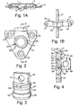
- FIGS 1A and 1B show conventional mountings.
- the first mounting 1 has an elongate body 3 with a mounting portion 5.
- the elongate body 3 is attached to the tent fabric via rivets 7, 9.
- the mounting portion 5 has an aperture 11 extending through it.
- the aperture 11 extends in a direction parallel to the direction of elongation of the mounting 1.
- a tent pole 13 can be slid through aperture 11.
- the mounting 15 again has an elongate body 17 which is attached to the tent fabric via rivets 19, 21.
- the mounting 15 also has a mounting portion 23 which has an aperture 25 extending through it, transverse to the elongate body 7.
- a tent pole 27 can be slid into the aperture 25.
- Figures 2, 3 and 4 show a mounting forming an embodiment of the invention.
- the mounting has a first member 31 which is planar and is designed to be attached flat against the fabric of the tent.
- the first member 31 has a triangular shape and has three rivet holes 33, 35 and 37 at the points of the triangle. In use, the first member will be riveted to the fabric using three rivets through holes 33, 35 and 37.
- a circular aperture 39 is provided in the centre of the first member 31. This aperture 39 is designed to receive the second rotatable member which will be described with reference to Figure 3.
- a stop member 41 is provided around the circumference of aperture 39. This stop member 41 is in the form of a lip 42 which extends approximately 3/4 of the way around the circumference of aperture 39 and prevents second member from rotating through more than 90° as will be described fully hereinafter.
- a clip section 43 shown at the top of the member will be described in detail with reference to Figure 4.
- Figure 3 shows the second member 45.
- the second member has a plate 49 which is integral with a base section 51.
- An aperture 47 extends through the plate 49.
- the aperture 47 can receive a tent pole, such that the tent pole (not shown) can slide through the second member.
- the base section 51 is a circular cylindrical stub.
- the cylinder diameter narrows at its middle to form a neck 52.
- the neck 52 separates the wider upper 54 and lower 56 cylinder portions.
- a lug 58 is formed on the circumferential surface of the upper cylinder portion 54.
- Figure 4 shows a cross section along line III-III of Figure 2 with the second member 45 located in the circular aperture 39 of the first member 31.
- the aperture 39 of the first member extends through the member and narrows at collar 55.
- the second member 45 is located in the first member 31 by snap-fitting, the lower portion 56 of the second member being chamfered and forced through the aperture 39.
- the collar portion 55, which defines the narrowest part of aperture 39, of the first member 31 is received in the narrow neck portion 52 of the second member 45, such that the second member 45 can rotate relative to the first member 31.
- the lip 42 extends around approximately 3/4 of the circumference at the top of the aperture 39, leaving a gap 40 which receives the lug 58.
- the lip 42 extends slightly less than 3/4 of the way around the circumference of the aperture 39 as the actual angle through which the second member can be rotated is defined by the lip 42 and the width of the lip 58. Therefore, to allow the second member to rotate fully through 90°, the lip must extended through slightly less than 270° to compensate for the width of the lug 58.
- the clip section 43 has a cylindrical cavity 57.
- the cavity 57 receives piping 59 which is located on the edge of tent fabric 61.
- the clip section 43 is particularly used when the first member is mounted to a solid surface such as a caravan wall to attach an awning or the like.
- FIG. 5 A tent extension or awning 71 is shown connected at point 73 to the caravan 75.
- the tent has two layers of material provided at its edges, both layers are provided with piping 81 and 85.
- the caravan wall 77 is provided with a cavity 79 for receiving piping 81 at the edge of the first layer of tent fabric 83.
- the piping 85 provided on the second layer of tent fabric is located in the channel 87 of the first member 31.
- the first member 31 is attached directly to the caravan wall.
- the second member 45 is mounted on the first member 31 as shown in Figure 3.
- the tent fabric is attached to the caravan wall 77 via cavity 79 and piping 81, and the first member 31 via cavity 43 and piping 85.
Landscapes
- Engineering & Computer Science (AREA)
- Architecture (AREA)
- Civil Engineering (AREA)
- Structural Engineering (AREA)
- Tents Or Canopies (AREA)
Applications Claiming Priority (2)
| Application Number | Priority Date | Filing Date | Title |
|---|---|---|---|
| GB9817475 | 1998-08-11 | ||
| GB9817475A GB2340533A (en) | 1998-08-11 | 1998-08-11 | Mounting for a tent |
Publications (3)
| Publication Number | Publication Date |
|---|---|
| EP0979912A2 true EP0979912A2 (fr) | 2000-02-16 |
| EP0979912A3 EP0979912A3 (fr) | 2001-05-30 |
| EP0979912B1 EP0979912B1 (fr) | 2003-06-04 |
Family
ID=10837069
Family Applications (1)
| Application Number | Title | Priority Date | Filing Date |
|---|---|---|---|
| EP19990306148 Expired - Lifetime EP0979912B1 (fr) | 1998-08-11 | 1999-08-03 | Elément de montage de tente |
Country Status (4)
| Country | Link |
|---|---|
| EP (1) | EP0979912B1 (fr) |
| DE (1) | DE69908510T2 (fr) |
| ES (1) | ES2199526T3 (fr) |
| GB (1) | GB2340533A (fr) |
Family Cites Families (9)
| Publication number | Priority date | Publication date | Assignee | Title |
|---|---|---|---|---|
| DE1042014B (de) * | 1956-04-10 | 1958-10-30 | Elliott Brothers (London) Limited, London | Schaltung zur Zwischenspeicherung der in magnetischen Registern gespeicherten Signale |
| FR80726E (fr) * | 1961-11-27 | 1963-06-07 | Fixation amovible d'auvent ou de store à un véhicule, en particulier aux caravanes | |
| FR2200869A5 (fr) * | 1972-09-25 | 1974-04-19 | Pollux Sarl | |
| US3863659A (en) * | 1974-03-19 | 1975-02-04 | Robert E Gillis | Shelter structure |
| US3986519A (en) * | 1975-09-18 | 1976-10-19 | Gillis Robert E | External flexed structure with pivotable fitting for an internal membrane |
| US4175305A (en) * | 1977-08-17 | 1979-11-27 | Gillis Robert E | Clip for gripping fabric or the like |
| US4195651A (en) * | 1978-10-10 | 1980-04-01 | American Ecosystems, Inc. | Ground engaging foot member |
| CA1284422C (fr) * | 1986-11-25 | 1991-05-28 | Abram Ewert | Fixation a pression pour articles en tissu |
| DE4403785A1 (de) * | 1993-10-25 | 1995-08-10 | Rud Ketten Rieger & Dietz | Ringschraube |
-
1998
- 1998-08-11 GB GB9817475A patent/GB2340533A/en not_active Withdrawn
-
1999
- 1999-08-03 ES ES99306148T patent/ES2199526T3/es not_active Expired - Lifetime
- 1999-08-03 DE DE1999608510 patent/DE69908510T2/de not_active Expired - Lifetime
- 1999-08-03 EP EP19990306148 patent/EP0979912B1/fr not_active Expired - Lifetime
Also Published As
| Publication number | Publication date |
|---|---|
| ES2199526T3 (es) | 2004-02-16 |
| GB2340533A (en) | 2000-02-23 |
| DE69908510T2 (de) | 2004-05-13 |
| GB9817475D0 (en) | 1998-10-07 |
| EP0979912B1 (fr) | 2003-06-04 |
| DE69908510D1 (de) | 2003-07-10 |
| EP0979912A3 (fr) | 2001-05-30 |
Similar Documents
| Publication | Publication Date | Title |
|---|---|---|
| US4470179A (en) | Fastener-clip | |
| US7309054B2 (en) | Universal clamp | |
| US7744046B1 (en) | Mounting device for electronic fish finder screen | |
| US5615699A (en) | Base bracket for tents and poles | |
| US4686748A (en) | Attachment device | |
| US7097117B2 (en) | Irrigation unit support stake and system | |
| EP0908638A1 (fr) | Dispositif de fixation avec écrou encagé | |
| US20050103816A1 (en) | Grill mounting apparatus for a vehicle | |
| US20080022451A1 (en) | Curtain Rod Assembly | |
| US20050194758A1 (en) | Pivotable suspension element | |
| US20220024735A1 (en) | Systems for winch rope interfaces and recovery rigging mountable to a winch fairlead and/or vehicle bumper | |
| US10081097B1 (en) | Tool for placement of cargo straps and edge protectors | |
| EP0979912A2 (fr) | Elément de montage de tente | |
| US8881669B2 (en) | Wrap preventing flag apparatus | |
| US20020148079A1 (en) | Twist-to-engage coupling | |
| CN100536709C (zh) | 带扣 | |
| US20070069519A1 (en) | Tube clip structure | |
| KR910008160Y1 (ko) | 텐트용 폴(Pole)홀더 | |
| ES2399395T3 (es) | Dispositivo para unir un brazo cargador a un vehículo | |
| KR200371597Y1 (ko) | 전주용 완금 고정장치의 완금지지구 구조 | |
| JP4835200B2 (ja) | 雨樋取付構造 | |
| AU781569B2 (en) | Universal flag clamp | |
| EP0984179A1 (fr) | Accessoire d'accrochage pour un mât, notamment un mât de tente | |
| JP3811860B2 (ja) | 竪樋支持具 | |
| US7461823B2 (en) | Apparatus and method for retaining a recreational vehicle attachment |
Legal Events
| Date | Code | Title | Description |
|---|---|---|---|
| PUAI | Public reference made under article 153(3) epc to a published international application that has entered the european phase |
Free format text: ORIGINAL CODE: 0009012 |
|
| AK | Designated contracting states |
Kind code of ref document: A2 Designated state(s): DE ES FR GB IT |
|
| AX | Request for extension of the european patent |
Free format text: AL;LT;LV;MK;RO;SI |
|
| PUAL | Search report despatched |
Free format text: ORIGINAL CODE: 0009013 |
|
| AK | Designated contracting states |
Kind code of ref document: A3 Designated state(s): AT BE CH CY DE DK ES FI FR GB GR IE IT LI LU MC NL PT SE |
|
| AX | Request for extension of the european patent |
Free format text: AL;LT;LV;MK;RO;SI |
|
| RIC1 | Information provided on ipc code assigned before grant |
Free format text: 7E 04H 15/32 A, 7E 04H 15/08 B, 7E 04H 15/64 B |
|
| 17P | Request for examination filed |
Effective date: 20010614 |
|
| AKX | Designation fees paid |
Free format text: DE ES FR GB IT |
|
| 17Q | First examination report despatched |
Effective date: 20020122 |
|
| GRAH | Despatch of communication of intention to grant a patent |
Free format text: ORIGINAL CODE: EPIDOS IGRA |
|
| GRAH | Despatch of communication of intention to grant a patent |
Free format text: ORIGINAL CODE: EPIDOS IGRA |
|
| GRAA | (expected) grant |
Free format text: ORIGINAL CODE: 0009210 |
|
| AK | Designated contracting states |
Designated state(s): DE ES FR GB IT |
|
| REG | Reference to a national code |
Ref country code: GB Ref legal event code: FG4D |
|
| REF | Corresponds to: |
Ref document number: 69908510 Country of ref document: DE Date of ref document: 20030710 Kind code of ref document: P |
|
| REG | Reference to a national code |
Ref country code: ES Ref legal event code: FG2A Ref document number: 2199526 Country of ref document: ES Kind code of ref document: T3 |
|
| ET | Fr: translation filed | ||
| PLBE | No opposition filed within time limit |
Free format text: ORIGINAL CODE: 0009261 |
|
| STAA | Information on the status of an ep patent application or granted ep patent |
Free format text: STATUS: NO OPPOSITION FILED WITHIN TIME LIMIT |
|
| 26N | No opposition filed |
Effective date: 20040305 |
|
| REG | Reference to a national code |
Ref country code: FR Ref legal event code: CA |
|
| PGFP | Annual fee paid to national office [announced via postgrant information from national office to epo] |
Ref country code: ES Payment date: 20080922 Year of fee payment: 10 |
|
| PGFP | Annual fee paid to national office [announced via postgrant information from national office to epo] |
Ref country code: IT Payment date: 20080827 Year of fee payment: 10 Ref country code: FR Payment date: 20080818 Year of fee payment: 10 |
|
| PGFP | Annual fee paid to national office [announced via postgrant information from national office to epo] |
Ref country code: GB Payment date: 20080813 Year of fee payment: 10 |
|
| GBPC | Gb: european patent ceased through non-payment of renewal fee |
Effective date: 20090803 |
|
| REG | Reference to a national code |
Ref country code: FR Ref legal event code: ST Effective date: 20100430 |
|
| PG25 | Lapsed in a contracting state [announced via postgrant information from national office to epo] |
Ref country code: FR Free format text: LAPSE BECAUSE OF NON-PAYMENT OF DUE FEES Effective date: 20090831 |
|
| REG | Reference to a national code |
Ref country code: ES Ref legal event code: FD2A Effective date: 20090804 |
|
| PG25 | Lapsed in a contracting state [announced via postgrant information from national office to epo] |
Ref country code: GB Free format text: LAPSE BECAUSE OF NON-PAYMENT OF DUE FEES Effective date: 20090803 |
|
| PG25 | Lapsed in a contracting state [announced via postgrant information from national office to epo] |
Ref country code: IT Free format text: LAPSE BECAUSE OF NON-PAYMENT OF DUE FEES Effective date: 20090803 |
|
| PG25 | Lapsed in a contracting state [announced via postgrant information from national office to epo] |
Ref country code: ES Free format text: LAPSE BECAUSE OF NON-PAYMENT OF DUE FEES Effective date: 20090804 |
|
| PGFP | Annual fee paid to national office [announced via postgrant information from national office to epo] |
Ref country code: DE Payment date: 20130731 Year of fee payment: 15 |
|
| REG | Reference to a national code |
Ref country code: DE Ref legal event code: R119 Ref document number: 69908510 Country of ref document: DE |
|
| REG | Reference to a national code |
Ref country code: DE Ref legal event code: R119 Ref document number: 69908510 Country of ref document: DE Effective date: 20150303 |
|
| PG25 | Lapsed in a contracting state [announced via postgrant information from national office to epo] |
Ref country code: DE Free format text: LAPSE BECAUSE OF NON-PAYMENT OF DUE FEES Effective date: 20150303 |