EP0979934B1 - Elektronische Drosselklappensteuerungseinheit - Google Patents
Elektronische Drosselklappensteuerungseinheit Download PDFInfo
- Publication number
- EP0979934B1 EP0979934B1 EP99115754A EP99115754A EP0979934B1 EP 0979934 B1 EP0979934 B1 EP 0979934B1 EP 99115754 A EP99115754 A EP 99115754A EP 99115754 A EP99115754 A EP 99115754A EP 0979934 B1 EP0979934 B1 EP 0979934B1
- Authority
- EP
- European Patent Office
- Prior art keywords
- opening
- throttle valve
- throttle
- value
- predicted
- Prior art date
- Legal status (The legal status is an assumption and is not a legal conclusion. Google has not performed a legal analysis and makes no representation as to the accuracy of the status listed.)
- Expired - Lifetime
Links
- 230000008859 change Effects 0.000 claims description 20
- 238000002485 combustion reaction Methods 0.000 claims description 12
- 230000006870 function Effects 0.000 description 97
- 230000001133 acceleration Effects 0.000 description 37
- 238000000034 method Methods 0.000 description 28
- 238000005070 sampling Methods 0.000 description 21
- 230000010354 integration Effects 0.000 description 18
- 238000010586 diagram Methods 0.000 description 12
- 239000000446 fuel Substances 0.000 description 12
- 230000007246 mechanism Effects 0.000 description 10
- 230000004044 response Effects 0.000 description 9
- 238000002347 injection Methods 0.000 description 6
- 239000007924 injection Substances 0.000 description 6
- 230000008569 process Effects 0.000 description 5
- 239000007789 gas Substances 0.000 description 4
- 230000007704 transition Effects 0.000 description 4
- 239000000498 cooling water Substances 0.000 description 3
- 230000002159 abnormal effect Effects 0.000 description 2
- 230000003197 catalytic effect Effects 0.000 description 2
- 230000000994 depressogenic effect Effects 0.000 description 2
- 238000001514 detection method Methods 0.000 description 2
- 239000000284 extract Substances 0.000 description 2
- 230000002265 prevention Effects 0.000 description 2
- 238000012935 Averaging Methods 0.000 description 1
- QVGXLLKOCUKJST-UHFFFAOYSA-N atomic oxygen Chemical compound [O] QVGXLLKOCUKJST-UHFFFAOYSA-N 0.000 description 1
- 230000001419 dependent effect Effects 0.000 description 1
- 230000004069 differentiation Effects 0.000 description 1
- 230000001747 exhibiting effect Effects 0.000 description 1
- 231100001261 hazardous Toxicity 0.000 description 1
- 230000015654 memory Effects 0.000 description 1
- 238000012544 monitoring process Methods 0.000 description 1
- 229910052760 oxygen Inorganic materials 0.000 description 1
- 239000001301 oxygen Substances 0.000 description 1
- 238000011144 upstream manufacturing Methods 0.000 description 1
Images








Classifications
-
- F—MECHANICAL ENGINEERING; LIGHTING; HEATING; WEAPONS; BLASTING
- F02—COMBUSTION ENGINES; HOT-GAS OR COMBUSTION-PRODUCT ENGINE PLANTS
- F02D—CONTROLLING COMBUSTION ENGINES
- F02D11/00—Arrangements for, or adaptations to, non-automatic engine control initiation means, e.g. operator initiated
- F02D11/06—Arrangements for, or adaptations to, non-automatic engine control initiation means, e.g. operator initiated characterised by non-mechanical control linkages, e.g. fluid control linkages or by control linkages with power drive or assistance
- F02D11/10—Arrangements for, or adaptations to, non-automatic engine control initiation means, e.g. operator initiated characterised by non-mechanical control linkages, e.g. fluid control linkages or by control linkages with power drive or assistance of the electric type
-
- F—MECHANICAL ENGINEERING; LIGHTING; HEATING; WEAPONS; BLASTING
- F02—COMBUSTION ENGINES; HOT-GAS OR COMBUSTION-PRODUCT ENGINE PLANTS
- F02D—CONTROLLING COMBUSTION ENGINES
- F02D11/00—Arrangements for, or adaptations to, non-automatic engine control initiation means, e.g. operator initiated
- F02D11/06—Arrangements for, or adaptations to, non-automatic engine control initiation means, e.g. operator initiated characterised by non-mechanical control linkages, e.g. fluid control linkages or by control linkages with power drive or assistance
- F02D11/10—Arrangements for, or adaptations to, non-automatic engine control initiation means, e.g. operator initiated characterised by non-mechanical control linkages, e.g. fluid control linkages or by control linkages with power drive or assistance of the electric type
- F02D11/105—Arrangements for, or adaptations to, non-automatic engine control initiation means, e.g. operator initiated characterised by non-mechanical control linkages, e.g. fluid control linkages or by control linkages with power drive or assistance of the electric type characterised by the function converting demand to actuation, e.g. a map indicating relations between an accelerator pedal position and throttle valve opening or target engine torque
-
- F—MECHANICAL ENGINEERING; LIGHTING; HEATING; WEAPONS; BLASTING
- F02—COMBUSTION ENGINES; HOT-GAS OR COMBUSTION-PRODUCT ENGINE PLANTS
- F02D—CONTROLLING COMBUSTION ENGINES
- F02D41/00—Electrical control of supply of combustible mixture or its constituents
- F02D41/02—Circuit arrangements for generating control signals
- F02D41/14—Introducing closed-loop corrections
- F02D41/1401—Introducing closed-loop corrections characterised by the control or regulation method
- F02D2041/1409—Introducing closed-loop corrections characterised by the control or regulation method using at least a proportional, integral or derivative controller
-
- F—MECHANICAL ENGINEERING; LIGHTING; HEATING; WEAPONS; BLASTING
- F02—COMBUSTION ENGINES; HOT-GAS OR COMBUSTION-PRODUCT ENGINE PLANTS
- F02D—CONTROLLING COMBUSTION ENGINES
- F02D41/00—Electrical control of supply of combustible mixture or its constituents
- F02D41/02—Circuit arrangements for generating control signals
- F02D41/14—Introducing closed-loop corrections
- F02D41/1401—Introducing closed-loop corrections characterised by the control or regulation method
- F02D2041/1413—Controller structures or design
- F02D2041/1422—Variable gain or coefficients
-
- F—MECHANICAL ENGINEERING; LIGHTING; HEATING; WEAPONS; BLASTING
- F02—COMBUSTION ENGINES; HOT-GAS OR COMBUSTION-PRODUCT ENGINE PLANTS
- F02D—CONTROLLING COMBUSTION ENGINES
- F02D35/00—Controlling engines, dependent on conditions exterior or interior to engines, not otherwise provided for
- F02D35/0007—Controlling engines, dependent on conditions exterior or interior to engines, not otherwise provided for using electrical feedback
Definitions
- the present invention relates to a control unit, and more particularly to a control unit for an electronically controlled throttle valve which is capable of raising response speed of an electronically controlled throttle valve having a structure in which an acceleration pedal and the throttle valve are not mechanically connected to each other.
- control of the number of revolutions of an internal combustion engine mounted on a vehicle has been performed in accordance with an amount of depression of an acceleration pedal disposed in a driver's compartment adjacent to a foot of a driver.
- internal combustion engines have generally incorporated a throttle valve disposed in a suction passage of the engine with the throttle valve connected to the acceleration pedal by a wire.
- the acceleration pedal When the acceleration pedal is depressed, the opening of the throttle valve is enlarged.
- an amount of air admitted into the internal combustion engine is enlarged, leading to an increased consumption of fuel.
- the number of revolutions of the internal combustion engine is enlarged.
- the structure of an electronically controlled throttle valve unit is shown in FIG. 1.
- the electronically controlled throttle valve unit 20 incorporates a throttle lever 16 connected to an acceleration pedal (not shown) by a wire; an accelerator opening sensor 15 contained in the throttle lever 16 for detecting an opening of an accelerator corresponding to an amount of depression of the accelerator pedal; an engine control unit (hereinafter called an "ECU") 10 to which the opening of the accelerator detected by the accelerator opening sensor 15 is input; a throttle motor 4 for opening/closing a throttle valve 3 disposed in a suction passage 2 of the internal combustion engine in accordance with an output of the ECU 10; a throttle opening sensor 5 for detecting an opening of the throttle valve 3; a lever 17 for withdrawal running; a return spring 18 for the throttle valve 3; and a relief spring 19 for the lever 17 for withdrawal running.
- the throttle motor 4 has a built-in electromagnetic clutch.
- the throttle lever 16 when the acceleration pedal is depressed in accordance with the intention of a driver, the amount of depression of the acceleration pedal is transmitted to the throttle lever 16 by the wire. As a result, the throttle lever 16 is rotated.
- the throttle lever 16 includes the accelerator opening sensor 15. In accordance with the angle of rotation of the throttle lever 16, the amount of depression of the acceleration pedal is detected. The amount of depression of the acceleration pedal detected by the accelerator opening sensor 15 is sent to the ECU 10.
- the ECU 10 determines the opening of the throttle valve 3 in accordance with the detected amount of depression of the acceleration pedal so as to rotate the throttle motor 4.
- the opening of the throttle valve 3 is detected by the throttle opening sensor 5 so as to be fed back to the ECU 10.
- the throttle motor 4 must be a motor exhibiting quick response and small power consumption.
- a signal transmitted from the throttle opening sensor 5 for detecting the opening of the throttle valve 3 is used.
- a feedback control of the throttle motor 4 is performed by using proportion (P), integration (I) and differentiation (D) (hereinafter simply called “PID control") to eliminate deviation from the signal transmitted from the accelerator opening sensor 15.
- the ECU 10 determines the opening of the throttle valve 3 in response to a signal representing an opening of the acceleration pedal. Thus, the ECU 10 directly outputs an operating signal to the throttle motor 4. The opening of the throttle valve 3 is detected by the throttle opening sensor 5 so as to be fed back to the ECU 10. Note that the throttle opening sensor 5 may be contained in the throttle motor 4.
- control constants of the PID control including terms P, I and D have been fixed values determined by a tuning operation to satisfy specifications required for all of the running states of the system. Therefore, the conventional control unit for the electronically controlled throttle valve using the PID control cannot provide an optimum value for each running state of the engine. As a result, response and stability of the throttle valve 3 deteriorate.
- Japanese Patent Application Laid-Open No. HEI 8-326561 has been disclosed to overcome the problem of the overshoot and undershoot with respect to the target value of the opening of the throttle valve.
- a method has been suggested with which the PID control of the throttle valve is performed such that a state of the operation of the throttle valve is determined. If the determination is made that the throttle valve is being operated in a state in which the opening is larger than the target opening which is determined in accordance with the amount of depression of the acceleration pedal, it is determined that overshoot of the throttle valve has occurred. Thus, the gain (the differential term D) for use in the PID control is changed.
- an object of the present invention is to provide a control unit for an electronically controlled throttle valve for performing PID control capable of realizing both high-speed response of the electronically controlled throttle valve and prevention of overshoot by raising the velocity at which the throttle valve is opened/closed in accordance with a commanded value for the opening of the throttle valve and by monitoring the opening/closing velocity of the throttle valve to reduce the opening/closing velocity of the throttle valve after a moment at which the opening of the throttle valve has approached the opening based on the commanded value.
- FIG. 2 schematically shows an electronically controlled fuel injection and multiple-cylinder internal combustion engine 1 incorporating the control unit for a throttle valve according to an embodiment of the present invention.
- a suction passage 2 of the internal combustion engine 1 is provided with a throttle valve 3 disposed downstream of an air cleaner (not shown).
- a throttle motor 4 which is an actuator for operating the throttle valve 3 is disposed at an end of a shaft of the throttle valve 3.
- a throttle opening sensor 5 for detecting the opening of the throttle valve 3 is disposed at another end of the foregoing shaft. That is, the throttle valve 3 according to this embodiment is an electronically controlled throttle which is opened/closed by the throttle motor 4.
- a surge tank 6 is disposed in the suction passage 2 at a position downstream of the throttle valve 3.
- a pressure sensor 7 for detecting the pressure of admitted air is disposed in the surge tank 6.
- a fuel injection valve 8 for supplying pressurized fuel from a fuel supply system to a suction port is disposed at a position downstream of the surge tank 6, the fuel injection valve 8 being provided for each cylinder.
- An output of the throttle opening sensor 5 and that of the pressure sensor 7 are supplied to an ECU (Engine Control Unit) 10 including a microcomputer.
- a water-temperature sensor 11 for detecting the temperature of cooling water is disposed in a cooling-water passage 9 of the cylinder block of the internal combustion engine 1.
- the water-temperature sensor 11 generates an analog-voltage electric signal corresponding to the temperature of the cooling water.
- the exhaust-gas passage 12 is provided with a three way catalytic converter (not shown) for simultaneously purifying hazardous components which are HC, CO and NOx contained in exhaust gas.
- An O 2 sensor 13 which is one of air-fuel ratio sensor is disposed in the exhaust-gas passage 12 at the position upstream of the catalytic converter. The O 2 sensor 13 generates an electric signal to correspond to the density of an oxygen component contained in the exhaust gas. Outputs of the water-temperature sensor 11 and the O 2 sensor 13 are supplied to the ECU 10.
- the ECU 10 is furthermore supplied with a signal representing an amount of depression of the acceleration pedal (an accelerator opening signal) supplied from an accelerator opening sensor 15 joined to the accelerator pedal 14 and arranged to detect the amount of depression of the accelerator. Moreover, the ECU 10 is supplied with engine speed Ne of the engine from a crank angle sensor joined to a distributor (not shown).
- the structure is arranged as described above.
- the ECU 10 When a key switch (not shown) is switched on, the ECU 10 is energized so that a program is started.
- the ECU 10 extracts outputs from the foregoing sensors and controls the throttle motor 4 for opening/closing the throttle valve 3 and the fuel injection valve 8 or the other actuators.
- the ECU 10 incorporates an A/D converter for converting analog signals supplied from the various sensors into digital signals.
- the ECU 10 incorporates an input/output interface 101 through which digital signals supplied from the various sensors and signals for operating the various actuators are input/output, a CPU 102 for performing a calculating process, memories, such as a ROM 103 and a RAM 104, and a clock 105.
- the foregoing units are connected to one another through a bus 106. Since the structure of the ECU 10 has been already known, further description is omitted.
- FIG. 4 is a block diagram showing functions of the ECU 10 shown in FIG. 2.
- a commanded-value setting function 110 produces a commanded value at the predetermined time T.
- the commanded value is supplied to a PID control function 111 constituted by a differential operation function 111D, a proportional operation function 111P and an integration operation function 111I.
- the PID control function 111 calculates an opening/closing velocity of the throttle valve.
- the PID control function 111 outputs a target value of the opening of the throttle valve which is determined by the opening/closing velocity of the throttle valve.
- the target value of the opening of the throttle valve is output to a duty output calculating function 112.
- the duty output calculating function 112 calculates a duty ratio of an operating signal for the throttle motor in accordance with the target value of the opening of the throttle valve.
- the duty ratio of an operating signal for the throttle motor is output to the throttle motor 4.
- the throttle motor 4 is rotated so that the opening of the throttle valve is changed.
- the opening of the throttle valve is detected by the throttle opening sensor 5. A detected value is fed back to the PID control function 111.
- the system for controlling the throttle valve has the above-mentioned functions.
- the control system according to the present invention has an acceleration/deceleration prediction calculating function 113 added thereto.
- the acceleration/deceleration prediction calculating function 113 extracts the output of the duty output calculating function 112 and controls the output of the duty output calculating function 112 by feeding back a predetermined signal to an input portion of the duty output calculating function 112.
- the opening of the throttle valve detected by the throttle opening sensor 5 is also input to the acceleration/deceleration prediction calculating function 113.
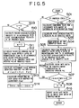
- a first embodiment of the control according to the present invention for use in the control unit having the above-mentioned structure shown in FIG. 4 will now be described with reference to a flow chart shown in FIG. 5.
- step 501 it is determined whether or not the present time is the sampling period T. If the present time is the sampling period T, the operation proceeds to step 502 where a present opening (the amount of depression of the acceleration pedal) detected by the accelerator opening sensor 15 is read as shown in FIGS. 3A and 3B. The read opening is made to be a present commanded value ⁇ CM of the opening of the throttle valve. In step 503, first opening/closing velocity V1 of the throttle valve is calculated in accordance with the magnitude of the commanded value ⁇ CM. Then, the operation proceeds to step 504.
- a present opening the amount of depression of the acceleration pedal
- the first opening/closing velocity V1 indicates an upper limit for a follow-up velocity of the opening of the throttle valve with respect to the commanded value ⁇ CM.
- the follow-up velocity of the opening of the throttle valve with respect to the commanded value ⁇ CM is guarded with the first opening/closing velocity V1.
- the first opening/closing velocity V1 may be determined in accordance with the magnitude of the commanded value ⁇ CM at the time at which the first opening/closing velocity V1 is calculated by forming the same into a map which is previously stored in the ROM 103. Also the first opening/closing velocity V1 of the throttle valve can be obtained by present control.
- the first opening/closing velocity V1 of the throttle valve can be obtained by producing a state equation by using parameters including the commanded value ⁇ CM, the amount of depression of the accelerator pedal, the voltage of a battery and the temperature detected at the time at which the first opening/closing velocity V1 is calculated.
- step 501 If it is determined in step 501 that the present time t1 is not the sampling period T, steps 502 and 503 are not performed. In this case, the operation proceeds to step 504.
- step 504 the opening ⁇ th of the throttle valve 3 is read in accordance with an output denoting the result of detection performed by the throttle opening sensor 5.
- step 505 predicted opening ⁇ e1 of the throttle valve after a lapse of predetermined time Ts (after next sampling cycle Ts) in accordance with the first opening/closing velocity V1 of the throttle valve calculated in step 503 and the present opening ⁇ th of the throttle valve 3.
- the predicted opening ⁇ e1 of the throttle valve is a quantity which is expressed as the difference from the present opening ⁇ th of the throttle valve.
- step 506 an amount of rotations of the throttle motor 4 for operating the throttle valve 3 is calculated as a drive duty ratio DD1 to correspond to the predicted opening ⁇ e1 of the throttle valve calculated in step 505.
- the drive duty ratio DD1 can be calculated in accordance with the map made to correspond to the predicted opening ⁇ e1 of the throttle valve.
- FIGS. 6 and 7 Examples of the foregoing map are shown in FIGS. 6 and 7.
- FIG. 6 shows an example of a map having the X-axis standing for predicted opening (the velocity) and the Y-axis standing for drive duty ratios DD1.
- the drive duty ratio DD1 corresponding to the predicted opening ⁇ e1 can be obtained.
- FIG. 7 shows an example of a map having the X-axis standing for the positions of the throttle valve, the Y-axis standing for the predicted openings of the throttle valve and the Z-axis standing for the drive duty ratios DD1.
- the map shown in FIG. 7 enables the value of the drive duty ratio DD1 corresponding to the predicted opening ⁇ e1 to be obtained in consideration of the present position of the throttle valve (the opening of the throttle valve). Therefore, a further accurate drive duty ratio DD1 can be obtained.
- the foregoing control is performed until the opening ⁇ th is enlarged to a predetermined opening near the commanded value ⁇ CM of the opening of the throttle valve 3.
- the predetermined opening varies depending on the performance of the engine.
- the predetermined opening is required to be, for example, about 85 % of the commanded value ⁇ CM of the opening of the throttle valve. Then, the description will be performed such that the predetermined opening is 85 % of the commanded value ⁇ CM of the opening of the throttle valve.
- step 507 it is determined whether or not the opening ⁇ th of the throttle valve 3 has been enlarged to the predetermined opening near the commanded value ⁇ CM of the opening of the throttle valve, that is, it is determined whether or not the opening ⁇ th of the throttle valve 3 has been enlarged to 85 % of the commanded value ⁇ CM. If ⁇ th ⁇ ⁇ CM ⁇ 0.85 in step 507, the drive duty ratio DD1 obtained by the procedure in step 502 to step 506 is as it is used to rotate the throttle motor 4. Therefore, if ⁇ th ⁇ ⁇ CM ⁇ 0.85 in step 507, the operation proceeds to step 508 where a flag n, to be described later, is made to be 0. Then in step 16, the drive duty ratio DD1 calculated in step 5 is output as the duty ratio for rotating the throttle motor 4. Thus, the foregoing routine is completed.
- step 509 it is determined whether or not ⁇ th ⁇ CM ⁇ 0.85 has been first satisfied in step 507 in accordance with the value of the flag. That is, if ⁇ th ⁇ ⁇ CM ⁇ 0.85 has been first satisfied in step 507, the value of the flag n is zero. Therefore, the process in steps 510 and 511 are performed. When the value of the flag n is zero, the operation proceeds to step 510 where second opening/closing velocity V2 of the throttle valve is calculated in accordance with the first opening/closing velocity V1 of the throttle valve.
- the second opening/closing velocity V2 of the throttle valve is smaller than the first opening/closing velocity V1 of the throttle valve.
- the second opening/closing velocity V2 can be calculated by using the map as shown in FIG. 8 and previously set in accordance with the first opening/closing velocity V1 of the throttle valve.
- the map shown in FIG. 8 is required to be corrected in accordance with the state of the throttle motor, the voltage of the battery mounted on the engine or the atmospheric temperature.
- step 511 the value of the flag n is made to be 1.
- step 512 the value of the flag n has been made to be 1. Therefore, the processes in steps 510 and 511 are not performed. In this case, the operation proceeds to step 512.
- the flag n is provided for causing the second opening/closing velocity V2 of the throttle valve to be calculated in step 510 only when ⁇ th ⁇ ⁇ CM ⁇ 0.85 is first satisfied in step 507.
- step 512 predicted opening ⁇ e2 of the throttle valve after a lapse of the predetermined time Ts is calculated in accordance with the second opening/closing velocity V2 of the throttle valve calculated in step 510 and the present opening ⁇ th of the throttle valve 3 read in step 504.
- step 513 difference ⁇ thdf between the predicted opening ⁇ e1 of the throttle valve calculated in step 505 and the predicted opening ⁇ e2 of the throttle valve calculated in step 512 is calculated.
- step 514 change DD ⁇ of the drive duty ratio DD1 of the throttle motor 4 which operates the throttle valve 3 is calculated to correspond to the difference ⁇ thdf.
- the change DD ⁇ of the drive duty ratio can be calculated by directly using the map caused to correspond to the predicted opening ⁇ e1 of the throttle valve.
- step 515 the drive duty ratio DD1 of the throttle valve calculated in step 506 is corrected with the change DD ⁇ of the drive duty ratio calculated in step 514.
- step 516 the corrected drive duty ratio DD1 of the throttle valve is output as the drive duty ratio of the throttle motor 4.
- the drive duty ratio DD1 which is output in step 516 is the value obtained in step 515 by correcting the drive duty ratio DD1 of the throttle motor 4 calculated in step 506.
- the corrected drive duty ratio DD1 is used to rotate the throttle motor 4.
- FIG. 9 is a time chart for use when the time t1 corresponds to the calculating cycles of the commanded value ⁇ CM and showing change in the commanded value ⁇ CM, the opening of the throttle valve (predicted openings ⁇ e1 and ⁇ e2) and the drive duty ratio DD1 of the throttle motor with time. It is assumed that the opening ⁇ th of the throttle valve is n° and the commanded value ⁇ CM calculated in step 502 is 5°.
- the first opening/closing velocity V1 of the throttle valve is calculated in accordance with the value of the commanded value ⁇ CM which is 5° (step 503). Then the value 5° as the present opening ⁇ th of the throttle valve is read (step 504). Then, the predicted opening ⁇ e1 of the throttle valve after a lapse of the sampling cycle Ts is calculated (step 505). Note that the predicted opening of the throttle valve after a lapse of the sampling cycle Ts is made to be F.
- the corresponding drive duty ratio DD1 of the throttle motor is calculated (step 806).
- the throttle motor is duty-rotated with the foregoing drive duty ratio DD1 (step 516).
- the duty rotation of the throttle motor is continued from time t1 to time t2 for period T1.
- the drive duty ratio DD1 of the throttle motor is accordingly changed to F', A', B', C' and E'.
- the control in the period T1 is the control using the PID control.
- the second opening/closing velocity V2 of the throttle valve is, at time t2, calculated to correspond to the first opening/closing velocity V1 of the throttle valve (step 510). Then, the predicted opening ⁇ e2 of the throttle valve after a lapse of sampling cycle Ts is calculated (step 512). Note that the predicted opening ⁇ e1 of the throttle valve after a lapse of sampling cycle Ts is made to be D" and the predicted opening ⁇ e2 of the throttle valve is made to be D.
- both of D" of the predicted opening ⁇ e1 corresponding to the first opening/closing velocity V1 of the throttle valve and D of the predicted opening ⁇ e2 are calculated.
- the difference ⁇ thdf between the two values is calculated (step 513).
- the change DD ⁇ of the duty ratio corresponding to the difference ⁇ thdf is calculated (step 514).
- the drive duty ratio DD1 of the throttle motor 4 is corrected with the change DD ⁇ of the duty ratio (step 515).
- the throttle motor is rotated with the corrected drive duty ratio DD1 in a period of T2 until time t3 at which the opening ⁇ th of the throttle valve coincides with the commanded value ⁇ CM.
- the period T2 is the period in which an acceleration/deceleration prediction calculation is performed in the PID control according to the present invention.
- the opening/closing velocity of the throttle valve is changed from the first opening/closing velocity V1 to the second opening/closing velocity V2 which is lower than the first opening/closing velocity V1.
- the change from the first opening/closing velocity V1 to the second opening/closing velocity V2 is not limited at the moment when the opening ⁇ th of the throttle valve has been enlarged to 85 % of the commanded value ⁇ CM.
- the timing may arbitrarily be selected in accordance with the performance of the engine.
- the change may be performed when the opening ⁇ th of the throttle valve is made to be full close or near full open.
- the predicted openings ⁇ e1 and ⁇ e2 of the throttle valve can appropriately be determined with respect to the commanded value ⁇ CM of the opening of the throttle valve as indicated with solid line RT.
- the drive duty ratio DD1 of the throttle motor can appropriately be determined as indicated with solid line RD. Therefore, the throttle valve can smoothly be operated without causing overshoot and undershoot.
- the conventional control encounters the fact that the predicted opening ⁇ e1 of the throttle valve is raised with respect to the commanded value ⁇ CM of the opening of the throttle valve even after time t2 as indicated with an alternate long and two short dashes line UT. Therefore, also the drive duty ratio DD1 of the throttle valve is raised as indicated with an alternate long and two short dash line UD. As a result, overshoot and undershoot of the throttle valve take place.
- the example shown in FIG. 9 is structured such that the gain of the PID control is appropriately determined.
- FIG. 10 Another example is shown in FIG. 10 in which the gain of the PID control is enlarged to cause the predicted opening ⁇ e1 of the throttle valve to always be guarded with the first opening/closing velocity V1.
- the predicted opening ⁇ e1 and ⁇ e2 of the throttle valve can appropriately be determined with respect to the commanded value ⁇ CM of the throttle valve as indicated with the solid line RT.
- the drive duty ratio DD1 of the throttle motor can appropriately be determined as indicated with the solid line RD. Therefore, the throttle valve can smoothly be rotated without causing overshoot and undershoot.
- the first and second opening/closing velocities V1 and V2 may be provided with allowances as indicated with dashed lines V1a, V1b and V2a, V2b shown in FIG. 10.
- the predicted opening ⁇ e1 of the throttle valve corresponding to the first opening/closing velocity V1 of the throttle valve is calculated.
- the difference ⁇ thdf between the predicted opening ⁇ e2 corresponding to the second opening/closing velocity V2 of the throttle valve and the predicted opening ⁇ e1 is calculated.
- the difference ⁇ thdf between the predicted opening ⁇ e2 of the throttle valve corresponding the second opening/closing velocity V2 of the throttle valve and the predicted opening ⁇ e1 of the throttle valve is calculated.
- the change DD ⁇ of the duty ratio corresponding to the difference ⁇ thdf is calculated.
- the change DD ⁇ of the duty ratio of the throttle motor which can be obtained from the predicted opening ⁇ e1 of the throttle valve corresponding to the first opening/closing velocity V1 of the throttle valve is corrected with the change DD ⁇ .
- the throttle motor thus, is rotated.
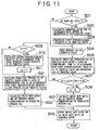
- FIG. 11 is a flow chart of a second embodiment of the present invention based on the foregoing control procedure.
- control procedure shown in FIG. 11 is similar to the control procedure shown in FIG. 5 except for a portion.
- the similar portions are given the same step numbers to those shown in FIG. 5 and the description thereof will be omitted.
- Steps 501 to 505 are the same as those of the procedure shown in FIG. 5.
- step 501 it is determined whether or not the present time is sampling cycle T.
- step 502 the commanded value ⁇ CM of the opening of the throttle valve is calculated in accordance with the present amount of depression of the acceleration pedal.
- step 503 the first opening/closing velocity V1 is calculated.
- step 504 the present opening ⁇ th of the throttle valve 3 is read.
- predicted opening ⁇ e1 of the throttle valve after a lapse of a predetermined time (sampling cycle) Ts is calculated.
- step 507 is performed after step 505 has been completed so that it is determined whether or not the opening ⁇ th of the throttle valve 3 is about 85 % of the commanded value ⁇ CM of the opening of the throttle valve.
- step 601 corresponding to step 506 in the control shown in FIG. 5 is performed. That is, in step 601, the drive duty ratio DD1 corresponding to the predicted opening ⁇ e1 is calculated. In step 516, the drive duty ratio DD1 calculated in step 601 is output as the drive duty ratio of the throttle motor 4. Thus, the foregoing routine is completed.
- step 509 it is determined whether or not ⁇ th ⁇ ⁇ CM ⁇ 0.85 has been first satisfied in step 507.
- the second opening/closing velocity V2 of the throttle valve is calculated in accordance with the first opening/closing velocity V1 of the throttle valve.
- step 511 the value of the flag n is made to be 1.
- step 512 the predicted opening ⁇ e2 of the throttle valve after a lapse of a predetermined time (sampling cycle) Ts is calculated.
- step 602 the drive duty ratio DD1 of the throttle motor corresponding to the predicted opening ⁇ e2 is calculated.
- the operation proceeds to step 516 where the drive duty ratio DD1 of the throttle valve is output as the drive duty ratio of the throttle motor 4.
- the drive duty ratio DD1 output in step 516 is the drive duty ratio DD1 of the throttle motor 4 corresponding to the predicted opening ⁇ e2 of the throttle valve calculated in step 602.
- the foregoing value is the same as the value of the drive duty ratio DD1 corrected in step 515 in the control shown in FIG. 5. Therefore, also this embodiment causes the throttle motor to be rotated similar to the control shown in FIG. 5.
- control of the operation of the throttle valve is performed while predicting the drive duty ratio of the throttle motor. Therefore, prediction of the time taken for the throttle valve to reach a commanded value after the commanded value has been changed can be performed. As a result, the air fuel ratio can accurately be controlled. Therefore, emission of the engine can be reduced. Hitherto, the operation of the throttle valve cannot be detected when the engine side controls the air fuel ratio.
- the present invention enables the operation of the throttle valve to somewhat detected. Therefore, an amount of admitted air can be detected in accordance with the opening of the throttle valve after a lapse of a predetermined time. Therefore, corresponding fuel injection can be performed. As a result, the emission of the engine can be improved.
- the electronically controlled throttle valve unit 30 is arranged to prevent stall of the engine when control has failed and maintain an amount of air required for the engine. To achieve this, a state in which the throttle valve 3 is opened by a predetermined opening is maintained even after the accelerator pedal 14 has been returned.
- the foregoing opening of the throttle valve 3 is called the opener opening.
- the foregoing opening is usually set by an opener opening setting mechanism having springs for urging the throttle valve 3 in the opening direction and the closing direction, respectively.
- FIG. 12A shows an example of the opener opening setting mechanism 40 of the electronically controlled throttle valve unit 30 from which an accelerator cable disposed between the accelerator pedal 14 and the throttle valve 3 has been omitted.
- the opener opening setting mechanism 40 urges the throttle valve 3 in the opening direction and the closing direction.
- FIGS. 12B to 12D show the operation of the opener opening setting mechanism 40. Note that the throttle opening sensor is omitted from FIG. 12A.
- the throttle motor 4 for rotating a rotational shaft 23 of the throttle valve 3 provided for the suction passage 2 is disposed at the end of the rotational shaft 23.
- a flange 22 is secured to another end of the rotational shaft 23.
- a first movable member 31 is provided for a predetermined position of the outer surface of the flange 22.
- a first spring 41 is arranged between the first movable member 31 and a throttle body (not shown) of the electronically controlled throttle valve unit 30. The first spring 41 urges the first movable member 31 in the direction in which the throttle valve 3 is opened.
- a movable ring 25 permitted to rotate around the rotational shaft 23 is fit to the rotational shaft 23 adjacent to the flange 22.
- a second movable member 32 arranged to be engaged to the first movable member 31 owning to the rotation of the movable ring 25 is provided for the outer surface of the movable ring 25.
- a second spring 42 is arranged between the second movable member 32 and the throttle body (not shown) of the electronically controlled throttle valve unit 30. The second spring 42 urges the second movable member 32 in the direction in which the throttle valve 3 is opened. In this embodiment, the urging force of the second spring 42 is set to be larger than that of the first spring 41.
- a stopper 26 for stopping the rotation of the second spring 42 is provided for the throttle body.
- the stopper 26 prevents exertion of the urging force of the second spring 42 on the throttle valve 3, the opening of which is smaller than the opener opening.
- the stopper 26 does not exert the influence on the operation of the first movable member 31.
- FIG. 12C shows the state in which the throttle valve 3 is opened at the opener opening.
- the second movable member 32 urged by the second spring 42 to rotate the throttle valve 3 in the opening direction is brought into contact with the stopper 26.
- the rotation of the second movable member 32 is interrupted. If the rotating force of a throttle motor (not shown) is not added to the rotational shaft 23 of the throttle valve in the foregoing state, the first movable member 31 is pulled by the first spring 41 so as to be brought into contact with the second movable member 32. As described above, the urging force of the first spring 41 is smaller than that of the second spring 42. Therefore, the throttle valve 3 maintains the opener opening in the state in which the rotating force of the throttle motor is not exerted on the rotational shaft 23.
- FIG. 12B shows the state in which the throttle valve 3 has completely closed the suction passage 2.
- the throttle motor is required to be rotated to exert rotating force larger than urging force F1 of the first spring 41 on the rotational shaft 23.
- a stopper (not shown) provided individually stops the rotation of the throttle valve 3 at the completely closed state. Therefore, the opening of the throttle valve 3 is not made to be a negative opening.
- FIG. 12D shows the state in which the throttle valve 3 has been opened at a predetermined opening which is larger than the opener opening.
- Both of the urging force F1 in a direction in which the throttle valve 3 is opened by the first spring 41 and urging force F2 in the direction in which the throttle valve 3 is opened by the second spring 42 are exerted on the first movable member 31 when the opening of the throttle valve 3 is larger than the opener opening.
- the urging force F1 of the first spring 41 is smaller than the urging force F2 of the second spring 42. Therefore, urging force (F2 - F1) obtained by subtracting the urging force F1 of the first spring 41 from the urging force F2 of the second spring 42 is exerted on the first movable member 31.
- urging force (F2 - F1) in the direction in which the throttle valve 3 is closed is exerted on the first movable member 31.
- rotating force larger than the urging force (F2 - F1) may be exerted from the throttle motor to the rotational shaft 23.
- a portion of the throttle motors for operating the electrically controlled throttle valve is able to uniformly generate torque over the full operation range of the engine.
- a portion of the throttle motors cannot perform the above-mentioned operation.
- the motor which is capable of uniformly generating torque over the full operation range of the engine is adapted to the electrically controlled throttle valve, the torque for operating the throttle valve is sometimes insufficient owning to the environment for the operation. Therefore, the throttle valve cannot sometimes be operated in a smooth manner even at an angle except for the angle in the vicinity of the opener opening.
- the next embodiment is arranged to be capable of smoothly opening/closing the throttle valve even if the throttle valve is operated in the opening or closing direction across the opener opening or if the throttle valve cannot smoothly be operated at an opening except for the opener opening.
- This embodiment is structured such that the opener opening setting mechanism 40 (not shown) for setting the opening of the throttle valve 3 is added to the structure shown in FIG. 2, which is disposed at the end of the rotational shaft of the throttle valve 3.
- FIG. 14 is a block diagram showing the functions of the ECU 10 for realizing a third embodiment.
- the commanded-value setting function 110 produces a commanded value at each predetermined time T, as described above.
- the commanded value is supplied to the PID control function 111 incorporating the differential operation function 111D, the proportional operation function 111P and the integration operation function 111I.
- the PID control function 111 calculates the opening/closing velocity of the throttle valve.
- the PID control function 111 outputs a target value of the opening of the throttle valve which is determined by the opening/closing velocity of the throttle valve.
- the target value of the opening of the throttle valve is supplied to the duty output calculating function 112.
- the duty output calculating function 112 calculates a duty ratio of an operating signal for the throttle motor in accordance with the target value of the opening of the throttle valve.
- the duty ratio of the operating signal for the throttle motor 4 is output to the throttle motor 4.
- the throttle motor 4 is rotated so that the opening of the throttle valve is changed.
- the opening of the throttle valve is detected by the throttle opening sensor 5.
- the sign of a value detected by the throttle opening sensor 5 is inverted, and then added to the commanded value by an adding function A1 so as to be fed back to the PID control function 111.
- the corresponding system for the usual throttle valve has the foregoing functions.
- the foregoing control system further incorporates a function (a differentiating function) 113 for calculating the movement velocity of the throttle valve, two switches 114 and 115 which are switched on/off by the function 113 for calculating the movement velocity of the throttle valve, a function 116 for calculating a predicted correcting term of the proportional operation, a function 117 for calculating a predicted correction term of the integration operation, and addition functions A2 and A3 for adding predicted correction terms of the predicted correction term of the proportional operation and the predicted correction term of the integration operation.
- a function (a differentiating function) 113 for calculating the movement velocity of the throttle valve
- two switches 114 and 115 which are switched on/off by the function 113 for calculating the movement velocity of the throttle valve
- a function 116 for calculating a predicted correcting term of the proportional operation
- a function 117 for calculating a predicted correction term of the integration operation
- addition functions A2 and A3 for
- the function 113 for calculating the movement velocity of the throttle valve detects the movement velocity of the throttle valve in accordance with the value detected by the throttle opening sensor 5 in a unit time. When the movement velocity of the throttle valve is lower than a predetermined value, the function 113 for calculating the movement velocity of the throttle valve switches the switches 114, 115 on.
- the function 116 for calculating a predicted correction term of the proportional operation and the function 117 for calculating a predicted correction term of the integration operation calculate the proportional operation and the integration operation, respectively, in accordance with a value detected by the throttle opening sensor 5.
- the predicted correction term calculated by the function 116 for calculating a predicted correction term of the proportional operation is, through the switch 114, output to the addition function A2 disposed between the proportional operation function 111P and the duty output calculating function 112.
- the predicted correction term calculated by the function 117 for calculating a predicted correction term of the integration operation is, through the switch 115, output to the addition function A3 disposed between the integration operation function 111I and the duty output calculating function 112.
- switches 114 and 115 are not mechanical switches and the foregoing switches are flags for operating the predicted correction terms 116 and 117.
- a case of the unit for controlling the electronically controlled throttle valve structured as shown in FIG. 14 will now be considered.
- This case is the case in which the opening/closing velocity of the throttle valve is set and the opening of the throttle valve is caused to follow up the set opening after a commanded value of a predetermined opening, for example, an opening of 5° is output.
- the relationship between the opening of the throttle valve and an actual value detected by the throttle opening sensor (expressed as throttle sensor in the drawing) will now be described in the case were the throttle valve has smoothly followed the opening/closing velocity of the throttle valve.
- the opening/closing velocity of the throttle valve with respect to the commanded value is sometimes the same until the opening of the throttle valve reaches the commanded value. In some cases, the foregoing opening/closing velocity is changed before the opening of the throttle valve reaches the commanded value.
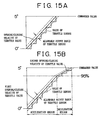
- FIG. 15A shows the case in which the opening/closing velocity of the throttle valve with respect to the commanded value is constant until the opening of the throttle valve reaches the commanded value.
- the opening/closing velocity of a predetermined throttle valve is set as indicated with a thick line.
- the throttle valve is operated to follow up the opening/closing velocity at t.
- the value of the throttle sensor is read at each time Ts.
- the foregoing case is the case in which the throttle valve has smoothly followed up the opening/closing velocity of the throttle valve. Therefore, output values of the throttle sensor follow the opening/closing velocity of the throttle valve and, therefore, the values are changed stepwise.
- an allowable range indicated with dashed lines is provided for the opening/closing velocity of the throttle valve. If the output value of the throttle sensor is deviated from the foregoing range, the predicted correction terms 116 and 117 shown in FIG. 14 are operated.
- FIG. 15B shows the case in which a plurality of opening/closing velocities of the throttle valve with respect to a commanded value exist until the opening of the throttle valve reaches the commanded value.
- a region for accelerating the throttle valve which is 95 % of 5° and a region for decelerating the throttle valve which is 95 % to 100 % are set.
- a first opening/closing velocity of the throttle valve is set in the acceleration region.
- a second opening/closing velocity which is lower than the first opening/closing velocity is set.
- the throttle valve is operated to follow the first and second opening/closing velocity.
- the value of the throttle sensor is read at each time Ts.
- the foregoing case is a case in which the throttle valve has smoothly followed the opening/closing velocity of the throttle valve. Therefore, the output value from the throttle sensor follows the first and second opening/closing velocities and, therefore, the value is changed stepwise. Also in the foregoing case, allowable ranges for the output value from the throttle sensor indicated with dashed lines are provided for the first and second opening/closing velocities. Therefore, also in the foregoing case, if the output value from the throttle sensor is deviated from the foregoing ranges, the predicted correction terms 116 and 117 shown in FIG. 14 are operated.
- the predicted correction terms 116 and 117 shown in FIG. 14 are operated when the deviation between the previous output of the throttle sensor and the present output is smaller than a reference value.
- the reference value is required to be half of the foregoing allowable range.
- FIG. 16 shows the case in which the operations of the predicted correction terms 116 and 117 shown in FIG. 14 which are performed when the output value of the throttle sensor has been deviated from the allowable ranges shown in FIGS. 15A and 15B.
- output difference PE (n - 2) satisfying the foregoing allowable range or larger than the reference value exists between the value of the throttle sensor at time T (n - 3) and that of the throttle sensor at time T (n - 2).
- no output difference exists between the value of the throttle sensor at time T (n - 2) and that of the throttle sensor at time T (n - 1).
- no output difference exists between the value of the throttle sensor at time T (n - 1) and that of the throttle sensor at time T (n).
- the predicted correction terms 116 and 117 shown in FIG. 14 calculate predicted correction terms at time T (n - 1) and time T (n).
- the throttle valve is operated on the assumption that the predicted opening of the throttle valve as indicated with an alternate long and short dash line has been obtained from the throttle sensor.
- the predicted opening of the throttle valve is the same as the output difference PE (n - 2) between the value of the throttle sensor at time T (n - 3) and that of the throttle sensor at time T (n - 2).
- the deviation PE (n - 2) between the opening of the throttle valve at the previous time T (n - 3) and the present opening of the throttle valve is calculated at time T (n - 2).
- the deviation PE (n - 2) is stored as a predicted value of the opening of the throttle valve at the next time T (n - 1). If a fact is detected at time T (n - 1) that no deviation exists between the present and pervious openings of the throttle valve, the detected opening of the throttle valve at time T (n - 1) is made to be a value obtained by adding the deviation PE (n - 2) calculated at the previous time T (n - 2) to the opening of the throttle valve at time T (n - 2).
- FIG. 17 is a time chart showing transition of the commanded value ⁇ CM, that of opening of the throttle valve of each of the present invention and the conventional structure, that of the value of the throttle sensor and that of the integrated value (examples 1 and 2) realized when a commanded value ⁇ CM of an opening ⁇ , for example, 10° has been output at time To. It is assumed that the opening of the throttle valve before time To is 0° (in a completely closed state). In the foregoing case, the opening of the throttle valve passes the opener opening ⁇ op to reach the commanded opening ⁇ after the commanded value ⁇ CM of the opening ⁇ has been output.
- the value of the throttle sensor at time T (n) is made as follows. That is, as indicated with an alternate long and short dash line, the value of the throttle sensor is the predicted value obtained by adding the deviation PE (n - 1) of the value of the throttle sensor at time T (n - 1) to the previous value of the throttle sensor.
- the value of the throttle sensor at time T(n + 1) is made as follows.
- the value of the throttle sensor is a predicted value obtained by adding the deviation PE(n - 1) of the value of the throttle sensor at time T(n - 1) to the previous value of the throttle sensor. That is, the value of the throttle sensor is the value obtained by adding a value which is two times the deviation PE(n - 1) of the value of the throttle sensor at time T(n - 1) to the value of the throttle sensor at time T(n + 1).
- the value of the throttle sensor at time T(n + 2) is made as follows.
- the value of the throttle sensor is a predicted value obtained by adding the deviation PE(n - 1) of the value of the throttle sensor at time T(n - 1) to the previous value of the throttle sensor. That is, the value of the throttle sensor is the value obtained by adding a value which is three times the deviation PE(n - 1) of the value of the throttle sensor at time T(n - 1) to the value of the throttle sensor at time T(n + 2).
- the gain A of the predicted correction term Ya is detected as a point on a plane PA of a two-dimensional map as shown in FIG. 18 in accordance with the position of the throttle sensor and the movement velocity of the throttle valve.
- the predicted correction term Ya at time T(n + 1) can be obtained by making N in the equation (1) to be 2 in accordance with the predicted value of the throttle sensor at time T(n).
- the predicted correction term Ya at time T (n + 2) can be calculated by making N in the equation (1) to be 3 in accordance with the predicted value of the throttle sensor at time T(n).
- the value of the integrating operation corrected with equation (2) is positioned between time T(n) and time T(n + 3) shown in FIG. 17 as indicated with a solid line.
- the value of the predicted correction term Ya is not calculated at time T(n + 3).
- the value of the integrating operation is restored to the original state.
- either of methods may be employed which include the method with which the value of the integration is immediately restored to the original state as shown in example 1 of FIG. 17 and the method with which the value of the integration is gradually restored to the original state as shown in example 2.
- the integrated value is corrected on the basis of a value of the predicted correction term Ya, also the differentiated value may similarly be corrected.
- the PID control according to this embodiment is structured such that when the value detected by the throttle sensor is free from change that is larger than the reference value, the predicted correction term Ya is calculated to correct the value of the proportion and the value of the integration.
- this embodiment is able to change the operation characteristic of the throttle valve 3 at the opener opening ⁇ op. Therefore, the period of stoppage of the throttle valve 3 at the opener opening ⁇ op can be shortened as indicated with a solid line H shown in FIG. 17.
- the conventional and simple PID control undesirably encounters elongation of the period of stoppage of the opening of the throttle valve near the opener opening ⁇ op as indicated with a dashed line shown in FIG. 17. Therefore, the throttle valve 3 cannot smoothly be operated.
- the next predicted opening of the throttle valve is previously calculated in accordance with the previous opening of the throttle valve and the present opening of the throttle valve.
- the predicted opening of the throttle valve calculated previously is employed as the present opening of the throttle valve to correct the rotating force of the motor.
- a comparison may be made between the predicted opening of the throttle valve calculated previously and the present opening of the throttle valve. If the comparison results in a fact that the deviation is larger than reference value M, the rotating force of the motor may be corrected in accordance with the deviation.
- the next predicted opening of the throttle valve is obtained in accordance with the deviation between the present opening of the throttle valve and the previous opening of the throttle valve.
- the next predicted opening of the throttle valve may be calculated by averaging the transition of the opening of the throttle valve which has occurred plural times.
- the example shown in FIG. 17 is arranged to perform control when the engine is accelerated by the opening of the throttle valve is enlarged.
- the control which is performed when the engine is decelerated by reducing the opening of the throttle valve may be structured such that the control for the acceleration process is inverted vertically. Therefore, the description of the foregoing control is omitted.
- step 701 it is determined whether or not the present time is the sampling period T. If the present time is the sampling period T, the operation proceeds to step 702 where a present opening (the amount of depression of the acceleration pedal) detected by the accelerator opening sensor 15 is read as shown in FIGS. 3A and 3B. The read opening is made to be a present commanded value ⁇ CM of the opening of the throttle valve. In step 703, opening/closing velocity V1 of the throttle valve is calculated in accordance with the magnitude of the commanded value ⁇ CM. Then, the operation proceeds to step 704.
- a present opening the amount of depression of the acceleration pedal
- the first opening/closing velocity V1 indicates a reference value for the following velocity of the opening of the throttle valve with respect to the commanded value ⁇ CM.
- the opening/closing velocity V1 is required to be formed into a map so as to be stored in the ROM 103 so as to be determined in accordance with the magnitude of the commanded value ⁇ CM at the time at which the opening/closing velocity V1 is calculated. Also the opening/closing velocity V1 of the throttle valve can be obtained by the present control.
- the opening/closing velocity V1 of the throttle valve can be obtained by producing a state equation by using parameters including the commanded value ⁇ CM, the amount of depression of the accelerator pedal, the voltage of a batter and the temperature detected at the time at which the first opening/closing velocity V1 is calculated. Then the foregoing state equation is solved so that the opening/closing velocity V1 is obtained.
- step 701 If it is determined in step 701 that the present time t1 is not the sampling period T, steps 702 and 703 are not performed. In this case, the operation proceeds to step 704.
- step 704 the previous opening of the throttle valve ⁇ tho is read.
- step 705 the present opening of the throttle valve ⁇ th is read as the present value.
- step 706 the deviation ⁇ th between the previous and present openings of the throttle valve is calculated. Moreover, the movement velocity Vth of the throttle valve is calculated.
- step 707 it is determined whether or not the absolute value of the deviation ⁇ th between the previous and present openings of the throttle valve calculated in step 706 is larger than the reference value K. If l ⁇ thl > K in step 707, the operation proceeds to step 708 where it is determined whether or not the movement velocity Vth of the throttle valve calculated in step 706 is larger than predetermined velocity L. If
- step 709 on opening obtained by adding the deviation ⁇ th between the previous and present openings of the throttle valve calculated in step 706 to the present opening ⁇ the of the throttle valve read in step 706 is made to be the next predicted opening ⁇ th of the throttle valve. Moreover, the present predicted opening ⁇ th of the throttle valve read in step 705 is stored as the previous opening ⁇ tho of the throttle valve. Then, the number N of times at which the fact has been detected that the deviation between the previous and present values detected by the throttle sensor has exceeded the allowable range or the same is smaller than the reference value K is made to be zero. Then, the operation proceeds to step 710. In step 710, the drive duty ratio of the throttle motor is calculated for the usual PID control so as to be output. Thus, the foregoing routine is completed.
- step 707 If it is determined in step 707 that
- step 711 one is added to the number N of times at which the fact has been detected that the deviation between the previous detected value and the present detected value obtained by the throttle sensor has been made to be larger than the allowable range or a fact has been detected that the deviation has been smaller that the reference value K. Then, the operation proceeds to step 712. In step 712, the predicted opening ⁇ the of the throttle valve calculated in the previous routine is read.
- step 713 the number N calculated in step 711 and the predicted opening ⁇ the of the throttle valve read in step 712 are used to calculate the predicted correction term Ya for the PID control in accordance with the foregoing equation (1).
- step 714 the predicted correction term Ya is subjected to the PID control in which the foregoing equation (2) is considered so that the drive duty ratio for the throttle motor is calculated and output. Thus, the foregoing routine is completed.
- the foregoing control is structured such that the next predicted opening of the throttle valve is previously calculated in accordance with the previous opening of the throttle valve and the present opening of the throttle valve. If the deviation between the previous opening of the throttle valve and the present opening of the throttle valve is not larger than the reference value K, the predicted opening of the throttle valve calculated previously is employed as the present opening of the throttle valve to correct the rotating force of the motor. Then, the procedure will now be described with reference to FIG. 20.
- the procedure is structured such that the predicted opening of the throttle valve calculated previously and the present opening of the throttle valve are compared with each other. If the comparison results in that the deviation between the two values is not smaller than the reference value M, the rotating force of the motor is corrected in accordance with the deviation.
- Steps 801 to 803 are the same as steps 701 to 703 shown in FIG. 19. Only when the present time is the sampling cycle T, the present amount of depression of the acceleration pedal is read to make the amount as the commanded value ⁇ CM of the present opening of the throttle valve. In accordance with the magnitude of the commanded value ⁇ CM, the opening/closing velocity V1 of the throttle valve is calculated. Then, the operation proceeds to step 804.
- step 804 the pervious opening ⁇ tho of the throttle valve and the predicted opening ⁇ th of the throttle valve calculated previously are read.
- step 805 the present opening ⁇ th of the throttle valve is read as the present value.
- step 806 the deviation ⁇ th between the previous and present openings of the throttle valve is calculated.
- the movement velocity Vth of the throttle valve is calculated.
- step 807 it is determined whether or not the absolute value
- step 809 an opening obtained by adding the deviation ⁇ th between the previous and present openings of the throttle valve to the present opening ⁇ th of the throttle valve is made to be a next predicted opening ⁇ the of the throttle valve. Moreover, the present opening ⁇ th of the throttle valve is stored as the previous opening ⁇ tho of the throttle valve. The number N of the abnormal conditions is made to be zero. Then, a usual PID control is performed in step 810 so that the drive duty ratio for the throttle motor is calculated and output. Thus, the foregoing routine is completed.
- step 807 If it is determined in step 807 that
- step 813 the PID control is performed such that the predicted correction term Ya is considered with the equation (2) so that the drive duty ratio of the throttle motor is calculated and output.
- the foregoing routine is completed.
- FIG. 21 is a block diagram showing functions of the ECU 10 shown in FIG. 2 to realize a fourth embodiment.
- the following arrangements are the same as those shown in FIG. 14.
- the structure of the PID control function 111 of the ECU 10 incorporates the differential operation function 111D, the proportional operation function 111P and integration operation function 111I, the structure of the duty output calculating function 112, and the structure that the opening of the throttle valve which is operated by the throttle motor 4 is detected by the throttle opening sensor 5 so as to be fed back to the PID control function 111. Therefore, illustration of the same portions will be omitted.
- the foregoing usual control system for the throttle valve is further including a function 121 for storing opening ⁇ th of the throttle valve, a function 122 for calculating deviation ⁇ th between the previous and present openings of the throttle valve, a function 123 for calculating predicted opening ⁇ the of the throttle valve and a switch 124.
- the function 121 for storing opening ⁇ th of the throttle valve stores the opening ⁇ th of the throttle valve detected by the throttle opening sensor 5 at each cycle Ts, the opening ⁇ th being stored together with detection time.
- the function 122 for calculating deviation ⁇ th between the previous and present openings of the throttle valve calculates the deviation ⁇ th between the previous opening ⁇ tho stored in the function 121 for storing opening ⁇ th of the throttle valve and the present opening ⁇ th of the throttle valve so as to compare the deviation ⁇ th with the reference value M (refer to the first embodiment).
- the function 123 for calculating predicted opening ⁇ the of the throttle valve predicts the opening ⁇ the after a lapse of the cycle Ts.
- the predicted opening ⁇ the of the throttle valve is stored.
- the function 122 for calculating deviation ⁇ th between the previous and present openings of the throttle valve connects the switch 124 to the throttle opening sensor 5 when the deviation ⁇ th between the previous and present openings of the throttle valve is larger than the reference value M.
- the switch 124 is connected to the function 123 for calculating predicted opening ⁇ the of the throttle valve.
- FIG. 22 is a block diagram showing functions of the ECU 10 shown in FIG. 2 to realize a fifth embodiment.
- the following arrangements are the same as those shown in FIG. 14.
- the structure of the PID control function 111 of the ECU 10 incorporates the differential operation function 111D, the proportional operation function 111P and integration operation function 111I, the structure of the duty output calculating function 112, and the structure that the opening of the throttle valve which is operated by the throttle motor 4 is detected by the throttle opening sensor 5 so as to be fed back to the PID control function 111. Therefore, the same portions are omitted from illustration.
- the foregoing usual control system for the throttle valve further includes a gain-constant changing switch 118, a gain-constant changing function 119 and a function 120 for calculating the deviation of the opening of the throttle valve.
- the gain-constant changing function 119 calculates the opening/closing velocity of the throttle valve when the gain-constant changing switch 118 is switched on.
- the gain-constant changing function 119 changes the gains of the differential operation function 111D, the proportional operation function 111P and the integration operation function 111I.
- the gain-constant changing switch 118 is switched on/off in accordance with the output of the function 120 for calculating the deviation of the opening of the throttle valve.
- the function 120 for calculating the deviation of the opening of the throttle valve calculates the deviation ⁇ th between the present opening ⁇ th of the throttle valve and the previous opening ⁇ tho of the throttle valve by the cycle Ts to monitor the value of the deviation.
- the function 120 for calculating the deviation of the opening of the throttle valve determines that the opening of the throttle valve is smoothly changed so that the state of the gain-constant changing switch 118 which is switched off is maintained. Then, the deviation ⁇ th is stored as the predicted opening ⁇ the of a next opening of the throttle valve.
- the function 120 for calculating the deviation of the opening of the throttle valve determines that the opening of the throttle valve is not smoothly moved.
- the function 120 for calculating the deviation of the opening of the throttle valve switches the gain-constant changing switch 118 on.
- the gains of the differential operation function 111D, the proportional operation function 111P and the integration operation function 111I are changed.
- the gain-constant changing switch 118 is not a mechanical switch and the switch is a flag for operating the gain-constant changing function 119.
- the PID control according to the fifth embodiment when the deviation ⁇ th between the previous and present openings of the throttle valve is not larger than the reference value K, the operation characteristic of the throttle valve 3 can be changed. Therefore, the opening of the throttle valve 3 can smoothly be changed. Therefore, if the opening of the throttle valve passes the opener opening ⁇ op, the force for operating the throttle valve can greatly be changed. As a result, the throttle valve can smoothly be operated in the vicinity of the opener opening.
- a first opening/closing velocity is set in accordance with the set commanded value, a present opening of the throttle valve (3) is read at each of second cycles shorter than the first predetermined cycles, the motor (4) is rotated to open/close the throttle valve (3) to follow a first predicted opening of the throttle valve (3) until the opening of the throttle valve (3) is smaller than the commanded value by a predetermined quantity, and the motor (4) is caused to open/close the throttle valve (3) to follow a second predicted opening of the throttle valve which is smaller than the first predicted opening of the throttle valve (3) after the cycle when the opening of the throttle valve (3) has been made smaller than the commanded value by a predetermined quantity.
Landscapes
- Engineering & Computer Science (AREA)
- Chemical & Material Sciences (AREA)
- Combustion & Propulsion (AREA)
- Mechanical Engineering (AREA)
- General Engineering & Computer Science (AREA)
- Electrical Control Of Air Or Fuel Supplied To Internal-Combustion Engine (AREA)
- Control Of Throttle Valves Provided In The Intake System Or In The Exhaust System (AREA)
Claims (5)
- Steuervorrichtung einer Brennkraftmaschine (1) mit:einem Beschleunigeröffnungssensor (15) zum Erfassen eines Beschleunigeröffnungswerts entsprechend einem Niederdrückbetrag eines Beschleunigerpedals (14),einem Drosselventilöffnungssensor (5) zum Erfassen eines Drosselöffnungswerts entsprechend einer Öffnung (θth) eines Drosselventils (3), das in einem Ansaugdurchgang (2) des Verbrennungsmotors (1) angeordnet ist,einem Drosselmotor (4) als Stellglied zum Öffnen und Schließen des Drosselventils (3) gemäß dem Beschleunigeröffnungswert und dem Drosselöffnungswert, undeiner elektronischen Steuereinheit (10), wobei die elektronische Steuereinheit (10) aufweisteine Anweisungswerteinstelleinrichtung (110) zum Einstellen eines Anweisungswerts (θCM) der Öffnung des Drosselventils (3) gemäß dem Beschleunigeröffnungswert bei vorbestimmten ersten Zyklen (T) und eine Steuervariableneinstelleinrichtung (111, 112, 113) zum Einstellen einer Steuervariablen und zum Abgeben der Steuervariablen an den Drosselmotor (4) als Betriebssignal für den Drosselmotor (4),dadurch gekennzeichnet, dass
die Steuervariableneinstelleinrichtung (111, 112, 113) eine erste Öffnungs-/Schließgeschwindigkeit (V1) des Drosselventils (3) gemäß dem Anweisungswert (θCM) berechnet und eine zweite Öffnungs-/Schließgeschwindigkeit (V2) des Drosselventils (3) gemäß der ersten Öffnungs-/Schließgeschwindigkeit (V1) berechnet, wobei die zweite Öffnungs-/Schließgeschwindigkeit (V2) kleiner als die erste Öffnungs-/Schließgeschwindigkeit (V1) ist und
wobei die Steuervariableneinstelleinrichtung (111, 112, 122) die Steuervariable derart einstellt, dass der Drosselmotor (4) das Drosselventil (3) gemäß der ersten Öffnungs-/Schließgeschwindigkeit (V1) öffnet, bis die Differenz zwischen einer vorliegenden Öffnung (θth) des Drosselventils (3) und dem Anweisungswert (θCM) des Drosselventils (3) geringer als ein vorbestimmter Wert ist, und das Drosselventil (3) darauf gemäß der zweiten Öffnungs-/Schließgeschwindigkeit (V2) öffnet, bis die Öffnung (θth) des Drosselventils (3) den Anweisungswert (θCM) erreicht. - Steuervorrichtung gemäß Anspruch 1, wobei die Steuervariableneinstelleinrichtung (111, 112, 113) einen Drosselöffnungswert, der durch den Drosselventilöffnungssensor (5) erfasst wird, als vorliegende Öffnung (θth) des Drosselventils (3) bei zweiten Zyklen (Ts) einliest, die kürzer als die ersten Zyklen (T) sind, eine erste vorhergesagte Öffnung (θe1) des Drosselventils (3) nach jedem zweiten Zyklus (Ts) gemäß der ersten Öffnungs-/Schließgeschwindigkeit (V1) berechnet, bis die vorliegende Öffnung (θth) des Drosselventils (3) eine vorbestimmte Öffnung erreicht, die kleiner als der Anweisungswert (θCM) um den vorbestimmten Wert ist, den Drosselmotor (4) anweist, das Drosselventil (3) zu öffnen/schließen, um der ersten vorhergesagten Öffnung (θe1) des Drosselventils (3) zu folgen, eine zweite vorhergesagte Öffnung (θe2) des Drosselventils (3) gemäß der zweiten Öffnungs-/Schließgeschwindigkeit (V2) berechnet, wenn die vorliegende Öffnung (θth) des Drosselventils (3) zumindest so groß wie die vorbestimmte Öffnung ist, und den Drosselmotor (4) anweist, das Drosselventil (3) zu öffnen/schließen, um der zweiten vorhergesagten Öffnung (θe2) des Drosselventils (3) zu folgen.
- Steuervorrichtung gemäß Anspruch 2, wobei die Steuervariableneinstelleinrichtung (111, 112, 113) ein Einschaltdauerverhältnis (DD1) der elektrischen Energie, die dem Drosselmotor (4) zugeführt wird, gemäß den ersten und zweiten vorhergesagten Öffnungen (θe1, θe2) des Drosselventils (3) berechnet und den Drosselmotor (4) anweist, sich bei dem berechneten Einschaltdauerverhältnis (DD1) zu drehen.
- Steuervorrichtung gemäß Anspruch 1, wobei die Steuervariableneinstelleinrichtung (111, 112, 113) einen Drosselöffnungswert, der durch den Drosselventilöffnungssensor (5) erfasst wird, als vorliegende Öffnung (θth) des Drosselventils (3) bei zweiten Zyklen (Ts) einliest, die kürzer als die ersten Zyklen (T) sind, eine erste vorhergesagte Öffnung (θe1) des Drosselventils (3) nach jedem zweiten Zyklus (Ts) gemäß der ersten Öffnungs-/Schließgeschwindigkeit (V1) berechnet, bis die vorliegende Öffnung (θth) des Drosselventils (3) eine vorbestimmte Öffnung erreicht, kleiner als der Anweisungswert (θCM) um den vorbestimmten Wert ist, den Drosselmotor (4) anweist, das Drosselventil (3) zu öffnen/schließen, um der ersten vorhergesagten Öffnung (θe1) des Drosselventils (3) zu folgen, und eine zweite vorhergesagte Öffnung (θe2) des Drosselventils (3) gemäß der zweiten Öffnungs-/Schließgeschwindigkeit (V2) berechnet, wenn die vorliegende Öffnung (θth) des Drosselventils (3) zumindest so groß wie die vorbestimmte Öffnung ist, wobei die Steuervariableneinstelleinrichtung (111, 112, 113) ferner eine Einrichtung zum Korrigieren der Steuervariablen, mit der das Drosselventil (3) geöffnet/geschlossen wird, gemäß einer Differenz (θthdf) zwischen der ersten vorhergesagten Öffnung (θe1) des Drosselventils (3) und der zweiten vorhergesagten Öffnung (θe2) des Drosselventils (3) aufweist, wobei die Einrichtung zum Korrigieren den Drosselmotor (4) anweist, sich gemäß der Differenz (θthdf) zwischen den ersten und zweiten vorhergesagten Öffnungen (θe1, θe2) zu drehen.
- Steuereinheit gemäß Anspruch 4, wobei die Steuervariableneinstelleinrichtung (111, 112, 113) ein Einschaltdauerverhältnis (DD1) der elektrischen Energie, die dem Drosselmotor (4) zugeführt wird, gemäß der ersten vorhergesagten Öffnung (θe1) berechnet und den Drosselmotor (4) anweist, sich gemäß der Differenz zwischen dem berechneten Einschaltdauerverhältnis (DD1) und einer Änderung (DDΔ) des Einschaltdauerverhältnisses gemäß der Differenz zwischen der ersten und der zweiten vorhergesagten Öffnung (θe1, θe2) des Drosselventils (3) zu drehen.
Priority Applications (1)
| Application Number | Priority Date | Filing Date | Title |
|---|---|---|---|
| EP06101480A EP1659278A2 (de) | 1998-08-10 | 1999-08-10 | Elektronische Drosselklappensteuerungseinheit |
Applications Claiming Priority (4)
| Application Number | Priority Date | Filing Date | Title |
|---|---|---|---|
| JP22603498A JP3744219B2 (ja) | 1998-08-10 | 1998-08-10 | 電子制御スロットル弁の制御装置 |
| JP22603498 | 1998-08-10 | ||
| JP34174098A JP3518377B2 (ja) | 1998-12-01 | 1998-12-01 | 電子制御スロットル弁の制御装置 |
| JP34174098 | 1998-12-01 |
Related Child Applications (1)
| Application Number | Title | Priority Date | Filing Date |
|---|---|---|---|
| EP06101480A Division EP1659278A2 (de) | 1998-08-10 | 1999-08-10 | Elektronische Drosselklappensteuerungseinheit |
Publications (3)
| Publication Number | Publication Date |
|---|---|
| EP0979934A2 EP0979934A2 (de) | 2000-02-16 |
| EP0979934A3 EP0979934A3 (de) | 2002-06-19 |
| EP0979934B1 true EP0979934B1 (de) | 2006-06-14 |
Family
ID=26526957
Family Applications (2)
| Application Number | Title | Priority Date | Filing Date |
|---|---|---|---|
| EP06101480A Withdrawn EP1659278A2 (de) | 1998-08-10 | 1999-08-10 | Elektronische Drosselklappensteuerungseinheit |
| EP99115754A Expired - Lifetime EP0979934B1 (de) | 1998-08-10 | 1999-08-10 | Elektronische Drosselklappensteuerungseinheit |
Family Applications Before (1)
| Application Number | Title | Priority Date | Filing Date |
|---|---|---|---|
| EP06101480A Withdrawn EP1659278A2 (de) | 1998-08-10 | 1999-08-10 | Elektronische Drosselklappensteuerungseinheit |
Country Status (3)
| Country | Link |
|---|---|
| US (4) | US6293249B1 (de) |
| EP (2) | EP1659278A2 (de) |
| DE (1) | DE69931858T2 (de) |
Families Citing this family (24)
| Publication number | Priority date | Publication date | Assignee | Title |
|---|---|---|---|---|
| US6378493B1 (en) * | 2000-08-02 | 2002-04-30 | Visteon Global Technologies, Inc. | Throttle position control system |
| US20030009240A1 (en) * | 2001-04-20 | 2003-01-09 | Honda Giken Kogyo Kabushiki Kaisha | Control system for plant |
| US6636783B2 (en) * | 2001-06-05 | 2003-10-21 | Honda Giken Kogyo Kabushiki Kaisha | Control system for throttle valve actuating device |
| JP2003193889A (ja) * | 2001-12-27 | 2003-07-09 | Denso Corp | 多気筒内燃機関の吸気制御装置 |
| US6675771B2 (en) * | 2001-12-28 | 2004-01-13 | Visteon Global Technologies, Inc. | Repeatability in control systems that utilize discretized feedback |
| JP3906717B2 (ja) * | 2002-03-19 | 2007-04-18 | トヨタ自動車株式会社 | アクセル開度設定装置およびこれを備える自動車 |
| JP3883917B2 (ja) * | 2002-07-11 | 2007-02-21 | 本田技研工業株式会社 | スロットル弁駆動装置の制御装置 |
| DE10308497A1 (de) * | 2003-02-26 | 2004-09-09 | Robert Bosch Gmbh | Verfahren und Vorrichtung zur Detektion der Betätigung eines Bedienelementes |
| JP4196345B2 (ja) * | 2004-02-18 | 2008-12-17 | 株式会社デンソー | バルブ開閉制御装置 |
| JP4391275B2 (ja) * | 2004-03-09 | 2009-12-24 | 三菱電機株式会社 | 多気筒エンジンの運転制御装置 |
| US7086379B2 (en) * | 2004-07-07 | 2006-08-08 | Buell Motorcycle Company | Power control device and method for a motorcycle |
| JP4356664B2 (ja) * | 2005-08-22 | 2009-11-04 | トヨタ自動車株式会社 | 内燃機関の制御装置 |
| DE102005052033A1 (de) * | 2005-10-31 | 2007-05-03 | Robert Bosch Gmbh | Verfahren und Vorrichtung zum Betreiben einer Brennkraftmaschine |
| JP4743057B2 (ja) * | 2006-09-12 | 2011-08-10 | トヨタ自動車株式会社 | 内燃機関のスロットル開度制御装置 |
| JP4654213B2 (ja) | 2007-03-30 | 2011-03-16 | 本田技研工業株式会社 | 駆動量制御装置 |
| US20080319630A1 (en) * | 2007-06-22 | 2008-12-25 | Esau Aguinaga | Adaptive air intake manifold valve actuator (IMVA) |
| US20090007884A1 (en) * | 2007-07-02 | 2009-01-08 | Bunne Jonathan M | Dual throttle assembly with electronic override |
| JP5279570B2 (ja) * | 2009-03-24 | 2013-09-04 | 本田技研工業株式会社 | エンジンのスロットル制御装置 |
| JP5566635B2 (ja) * | 2009-07-08 | 2014-08-06 | 株式会社デンソー | 回転機の制御装置 |
| US8321059B2 (en) | 2009-08-28 | 2012-11-27 | Fisher Controls International, Llc | Apparatus, methods and articles of manufacture to calibrate valve-mounted instruments |
| JP5987877B2 (ja) * | 2013-10-04 | 2016-09-07 | 株式会社デンソー | 電子スロットル |
| CN104481707B (zh) * | 2014-12-01 | 2017-02-22 | 南京奥联汽车电子技术有限公司 | 电子节气门的末端控制时点预测方法及电子节气门系统 |
| CN108138660B (zh) * | 2015-09-25 | 2020-12-18 | 日产自动车株式会社 | 阀控制装置 |
| CN114893308B (zh) * | 2022-05-25 | 2023-06-06 | 徐州徐工挖掘机械有限公司 | 一种挖掘机油门控制方法 |
Family Cites Families (12)
| Publication number | Priority date | Publication date | Assignee | Title |
|---|---|---|---|---|
| JP2559480B2 (ja) * | 1988-11-07 | 1996-12-04 | 株式会社日立製作所 | 電子式弁開度制御装置 |
| US5406920A (en) * | 1992-12-21 | 1995-04-18 | Honda Giken Kogyo Kabushiki Kaisha | Apparatus for controlling the position of control member |
| DE19513370B4 (de) * | 1995-04-08 | 2008-06-12 | Robert Bosch Gmbh | Verfahren und Vorrichtung zur Steuerung der Leistung einer Brennkraftmaschine |
| JP3460383B2 (ja) | 1995-05-31 | 2003-10-27 | 株式会社デンソー | 内燃機関のスロットル制御装置 |
| GB9601479D0 (en) * | 1996-01-25 | 1996-03-27 | Rover Group | A powertrain control system |
| JP3422165B2 (ja) | 1996-03-06 | 2003-06-30 | トヨタ自動車株式会社 | 車両の制御装置 |
| DE19610210B4 (de) * | 1996-03-15 | 2011-12-08 | Robert Bosch Gmbh | Verfahren zur Lageregelung eines Stellelements einer Brennkraftmaschine |
| US5749343A (en) * | 1996-10-07 | 1998-05-12 | General Motors Corporation | Adaptive electronic throttle control |
| JP3770675B2 (ja) * | 1996-12-19 | 2006-04-26 | トヨタ自動車株式会社 | スロットル制御装置 |
| DE19703685C2 (de) * | 1997-01-31 | 2003-06-18 | Siemens Ag | Verfahren und Einrichtung zum Steuern einer Brennkraftmaschine |
| JP3458935B2 (ja) * | 1997-02-20 | 2003-10-20 | 株式会社デンソー | 内燃機関の電子スロットル制御装置 |
| JP3710073B2 (ja) * | 1997-03-31 | 2005-10-26 | 三菱自動車工業株式会社 | 吸気絞り弁制御装置 |
-
1999
- 1999-08-06 US US09/369,634 patent/US6293249B1/en not_active Expired - Fee Related
- 1999-08-10 EP EP06101480A patent/EP1659278A2/de not_active Withdrawn
- 1999-08-10 EP EP99115754A patent/EP0979934B1/de not_active Expired - Lifetime
- 1999-08-10 DE DE69931858T patent/DE69931858T2/de not_active Expired - Lifetime
-
2001
- 2001-07-30 US US09/916,575 patent/US6502548B2/en not_active Expired - Fee Related
- 2001-07-30 US US09/916,441 patent/US6561162B2/en not_active Expired - Fee Related
- 2001-07-30 US US09/916,574 patent/US6494181B2/en not_active Expired - Fee Related
Also Published As
| Publication number | Publication date |
|---|---|
| US20020134352A1 (en) | 2002-09-26 |
| US20010039940A1 (en) | 2001-11-15 |
| EP1659278A2 (de) | 2006-05-24 |
| US20020139348A1 (en) | 2002-10-03 |
| US6502548B2 (en) | 2003-01-07 |
| US6561162B2 (en) | 2003-05-13 |
| DE69931858D1 (de) | 2006-07-27 |
| EP0979934A2 (de) | 2000-02-16 |
| US6293249B1 (en) | 2001-09-25 |
| EP0979934A3 (de) | 2002-06-19 |
| US6494181B2 (en) | 2002-12-17 |
| DE69931858T2 (de) | 2006-12-07 |
Similar Documents
| Publication | Publication Date | Title |
|---|---|---|
| US6293249B1 (en) | Unit for controlling electronically controlled throttle valve | |
| KR100238367B1 (ko) | 공기량선행 연료공급량추종 제어방식의 내연기관 제어장치 | |
| EP0189190B1 (de) | Steuerungssystem für das Drosselventil einer Innenbrennkraftmaschine | |
| KR880002075B1 (ko) | 스파아크 점화 내연기관용 전자(電子)조절식 연료 분사장치 | |
| KR900003858B1 (ko) | 차량용 엔진의 제어장치 | |
| US5611309A (en) | Throttle valve control system for internal combustion engines | |
| US7305295B2 (en) | Throttle limiting for an internal combustion engine | |
| US4727838A (en) | Apparatus for controlling internal combustion engine | |
| US4729356A (en) | Control systems for vehicle engines | |
| US5307777A (en) | Throttle opening control system for automotive engine | |
| JP3710073B2 (ja) | 吸気絞り弁制御装置 | |
| US4474151A (en) | Engine revolution speed control device | |
| EP1323564B1 (de) | Steuerungssystem eines Hybridfahrzeugs | |
| GB2117936A (en) | Automatic control of idling speed | |
| US5499952A (en) | Method and arrangement for controlling the power of a drive unit of a motor vehicle | |
| EP0962640B1 (de) | Steuerapparat für die Steuerung eines Verbrennungsmotors | |
| JP3518377B2 (ja) | 電子制御スロットル弁の制御装置 | |
| JP3744219B2 (ja) | 電子制御スロットル弁の制御装置 | |
| JP3294894B2 (ja) | 車両の退避走行装置 | |
| JP2566144B2 (ja) | 内燃機関のスロットル弁制御装置 | |
| JP3658931B2 (ja) | 内燃機関の制御装置 | |
| JP3646545B2 (ja) | 電子制御スロットル弁の制御装置 | |
| EP4549720A1 (de) | Elektronisches drosselsteuerungsverfahren und elektronische drosselsteuerungsvorrichtung | |
| JP2956445B2 (ja) | 機関の吸気制御装置 | |
| JPS6181533A (ja) | 内燃エンジンの減速状態判別装置およびこれを用いた減速時の空燃比制御装置 |
Legal Events
| Date | Code | Title | Description |
|---|---|---|---|
| PUAI | Public reference made under article 153(3) epc to a published international application that has entered the european phase |
Free format text: ORIGINAL CODE: 0009012 |
|
| 17P | Request for examination filed |
Effective date: 19990810 |
|
| AK | Designated contracting states |
Kind code of ref document: A2 Designated state(s): AT BE CH CY DE DK ES FI FR GB GR IE IT LI LU MC NL PT SE |
|
| AX | Request for extension of the european patent |
Free format text: AL;LT;LV;MK;RO;SI |
|
| PUAL | Search report despatched |
Free format text: ORIGINAL CODE: 0009013 |
|
| AK | Designated contracting states |
Kind code of ref document: A3 Designated state(s): AT BE CH CY DE DK ES FI FR GB GR IE IT LI LU MC NL PT SE |
|
| AX | Request for extension of the european patent |
Free format text: AL;LT;LV;MK;RO;SI |
|
| AKX | Designation fees paid |
Designated state(s): DE FR GB |
|
| 17Q | First examination report despatched |
Effective date: 20050118 |
|
| GRAP | Despatch of communication of intention to grant a patent |
Free format text: ORIGINAL CODE: EPIDOSNIGR1 |
|
| GRAS | Grant fee paid |
Free format text: ORIGINAL CODE: EPIDOSNIGR3 |
|
| GRAA | (expected) grant |
Free format text: ORIGINAL CODE: 0009210 |
|
| AK | Designated contracting states |
Kind code of ref document: B1 Designated state(s): DE FR GB |
|
| REG | Reference to a national code |
Ref country code: GB Ref legal event code: FG4D |
|
| REF | Corresponds to: |
Ref document number: 69931858 Country of ref document: DE Date of ref document: 20060727 Kind code of ref document: P |
|
| ET | Fr: translation filed | ||
| PLBE | No opposition filed within time limit |
Free format text: ORIGINAL CODE: 0009261 |
|
| STAA | Information on the status of an ep patent application or granted ep patent |
Free format text: STATUS: NO OPPOSITION FILED WITHIN TIME LIMIT |
|
| 26N | No opposition filed |
Effective date: 20070315 |
|
| REG | Reference to a national code |
Ref country code: GB Ref legal event code: 746 Effective date: 20090616 |
|
| PGFP | Annual fee paid to national office [announced via postgrant information from national office to epo] |
Ref country code: GB Payment date: 20120808 Year of fee payment: 14 |
|
| PGFP | Annual fee paid to national office [announced via postgrant information from national office to epo] |
Ref country code: FR Payment date: 20120823 Year of fee payment: 14 Ref country code: DE Payment date: 20120808 Year of fee payment: 14 |
|
| GBPC | Gb: european patent ceased through non-payment of renewal fee |
Effective date: 20130810 |
|
| PG25 | Lapsed in a contracting state [announced via postgrant information from national office to epo] |
Ref country code: DE Free format text: LAPSE BECAUSE OF NON-PAYMENT OF DUE FEES Effective date: 20140301 |
|
| REG | Reference to a national code |
Ref country code: DE Ref legal event code: R119 Ref document number: 69931858 Country of ref document: DE Effective date: 20140301 |
|
| REG | Reference to a national code |
Ref country code: FR Ref legal event code: ST Effective date: 20140430 |
|
| PG25 | Lapsed in a contracting state [announced via postgrant information from national office to epo] |
Ref country code: GB Free format text: LAPSE BECAUSE OF NON-PAYMENT OF DUE FEES Effective date: 20130810 |
|
| PG25 | Lapsed in a contracting state [announced via postgrant information from national office to epo] |
Ref country code: FR Free format text: LAPSE BECAUSE OF NON-PAYMENT OF DUE FEES Effective date: 20130902 |