EP0979943A2 - Linearkompressor - Google Patents
Linearkompressor Download PDFInfo
- Publication number
- EP0979943A2 EP0979943A2 EP99115774A EP99115774A EP0979943A2 EP 0979943 A2 EP0979943 A2 EP 0979943A2 EP 99115774 A EP99115774 A EP 99115774A EP 99115774 A EP99115774 A EP 99115774A EP 0979943 A2 EP0979943 A2 EP 0979943A2
- Authority
- EP
- European Patent Office
- Prior art keywords
- piston
- cylinder
- holding member
- cylindrical holding
- fixed
- Prior art date
- Legal status (The legal status is an assumption and is not a legal conclusion. Google has not performed a legal analysis and makes no representation as to the accuracy of the status listed.)
- Withdrawn
Links
Images


Classifications
-
- F—MECHANICAL ENGINEERING; LIGHTING; HEATING; WEAPONS; BLASTING
- F04—POSITIVE - DISPLACEMENT MACHINES FOR LIQUIDS; PUMPS FOR LIQUIDS OR ELASTIC FLUIDS
- F04B—POSITIVE-DISPLACEMENT MACHINES FOR LIQUIDS; PUMPS
- F04B35/00—Piston pumps specially adapted for elastic fluids and characterised by the driving means to their working members, or by combination with, or adaptation to, specific driving engines or motors, not otherwise provided for
- F04B35/04—Piston pumps specially adapted for elastic fluids and characterised by the driving means to their working members, or by combination with, or adaptation to, specific driving engines or motors, not otherwise provided for the means being electric
- F04B35/045—Piston pumps specially adapted for elastic fluids and characterised by the driving means to their working members, or by combination with, or adaptation to, specific driving engines or motors, not otherwise provided for the means being electric using solenoids
Definitions
- the present invention relates to a linear compressor to which little load in a direction perpendicular to a direction of reciprocating motion of a piston is applied, and more particularly, to a linear compressor in which a linear motor is disposed around an outer periphery of a piston, and it is possible to easily mount the linear motor with high precision.
- HCFC-based refrigerant such as R22 which is utilized in an air conditioner and is a stable compound destroys ozone layer.
- HFC-based refrigerants are utilized as alternative refrigerants of HCFC, but these HFC-based refrigerants have the nature for facilitating the global warming. Therefore, there is a tendency to start employing HC-based refrigerants which do not destroy the ozone layer and largely affect the global warming.
- the HC-based refrigerants are flammable, it is necessary to prevent explosion or ignition so as to ensure the safety, and it is required to reduce the amount of use of the refrigerant to the utmost.
- HC-based refrigerants do not have lubricity and are prone to be solved into lubricants. Therefore, when HC-based refrigerants are used, oil free or oil poor compressor is required, and a linear compressor in which little load is applied in a direction perpendicular to an axis of a piston.
- the movable member is a permanent magnet
- a linear compressor comprising: a cylinder supported in a vessel by a supporting mechanism; a piston concentric with the cylinder and movably supported along an axial direction of the cylinder, and a linear motor for forming a magnetic path by a movable member fixed to the piston and a stationary member fixed to the cylinder to generate a thrust force; the linear motor being disposed around an outer periphery of the piston, wherein the piston is provided with a flange having a side surface formed concentrically with an axial of the piston, the movable member is held by a cylindrical holding member, and the cylindrical holding member is fixed such that the cylindrical holding member is in contact with the side surface of the flange.
- the cylindrical holding member can also be provided concentrically with the piston. Since the cylindrical holding member holds the movable member, the movable member is disposed concentrically with the piston, and can be positioned precisely. Further, the mounting operation of the movable member is also easy. Furthermore, the overall length of the movable member and the piston constituting the moving member can be shortened as compared with a structure in which the piston and the linear motor are juxtaposed in the moving direction, even if the piston is slightly inclined, little influence is exerted on the gap of the movable member, which contributes to enhancement of efficiency of the compressor.
- a linear compressor comprising: a cylinder supported in a vessel by a supporting mechanism; a piston concentric with the cylinder and movably supported along an axial direction of the cylinder, and a linear motor for forming a magnetic path by a movable member fixed to the piston and a stationary member fixed to the cylinder to generate a thrust force; the linear motor being disposed around an outer periphery of the piston, wherein the piston is provided with a flange which has a side surface formed concentrically with an axial of the piston and an end surface formed perpendicular to the axis of the piston, the movable member is held by a cylindrical holding member, and the cylindrical holding member is fixed such that the cylindrical holding member is in contact with the side surface and the end surface of the flange.
- the cylindrical holding member is disposed concentrically with the piston, and the movable member held by the cylindrical holding member is disposed concentrically with the piston and positioned precisely. Further, the mounting operation of the movable member is also easy. Furthermore, the overall length of the movable member and the piston constituting the moving member can be shortened as compared with a structure in which the piston and the linear motor are juxtaposed in the moving direction, even if the piston is slightly inclined, little influence is exerted on the gap of the movable member, which contributes to enhancement of efficiency of the compressor.
- the cylinder is provided with a flange portion, the flange portion is formed concentrically with an axis of the cylinder, the stationary member constituting the linear motor is formed cylindrically, and the stationary member is fixed to the flange portion.
- the stationary member can be disposed concentrically with the cylinder, the positional relation between the movable member and the stationary member disposed concentrically with the piston can be maintained precisely, and the gap between the movable member and the stationary member can be reduced. Therefore, the efficiency of the compressor can be enhanced.
- the movable member is a permanent magnet
- the stationary member is an outer yoke and a coil.
- the stationary member is concentrically fixed to the cylinder side and the permanent magnet is concentrically held on the piston side, the positional precision therebetween is enhanced. Further, since the coil is the stationary member, it is easy to carry out wiring for energizing the coil.
- an outer peripheral surface of the cylinder is formed concentrically with an axis of the cylinder, the stationary member constituting the linear motor is formed cylindrically, and the stationary member is held by the cylinder such that the stationary member is in contact with the outer peripheral surface.
- the movable member is concentric with the stationary member, and it is possible to easily reduce the size and the gap, and to enhance the efficiency of the compressor.
- the movable member is a permanent magnet, and the stationary member in an inner yoke.
- both the permanent magnet and the inner yoke can be disposed concentrically with each other, and since the inner yoke is not disposed at the movable side, the weight of the movable member side can be reduced.
- a linear compressor comprising: a cylinder supported in a vessel by a supporting mechanism; a piston concentric with the cylinder and movably supported along an axial direction of the cylinder, and a linear motor for forming a magnetic path by a permanent magnet fixed to the piston and a coil fixed to the cylinder to generate a thrust force; the linear motor being disposed around an outer periphery of the piston, wherein the permanent magnet is sandwiched and fixed between a cylindrical holding member fixed to the piston and a cylindrical body concentric with the cylindrical holding member.
- the permanent magnet is provided around an outer periphery of the cylindrical holding member, and the cylindrical body is provided around an outer periphery of the permanent magnet.
- the cylindrical holding member or the cylindrical body is made of metal material, and the cylindrical holding member or the cylindrical body is provided with a slit.
- the linear compressor broadly comprises a cylinder 10, a piston 20, a movable member 40 as well as stationary member 50 both constituting a linear motor , a discharge mechanism 60, a spring mechanism 70, a vessel 80, a supporting mechanism 90 and the like.
- the cylinder 10 is integrally provided with a flange portion 11, a boss 12 extending leftward in the drawings (forward) from the flange portion 11, and a cylindrical member 13 for holding the piston 20.
- a space 14 is formed which forms a compressing chamber in which a piston body 28 is disposed.
- a front end of the space 14 is opened.
- a suction port 15 provided at the flange portion 11 side is in communication with the space 14.
- a cylinder bore 16 formed in the cylindrical member 13 is in communication with the space 14, and a rear end of the cylindrical member 13 is opened.
- a thin ring body 17 made of metal material is fitted into the cylinder bore 16.
- the cylinder 10 is made of aluminum material, and the ring body 17 is provided for reducing the mechanical loss.
- the piston 20 comprises rod 22 forming an inner hole 21, and a piston body 28.
- the piston 20 is made of aluminum material.
- the piston 20 comprises the rod 22 and a thin steel liner 23 fitted around the outer periphery of the piston body 28.
- the piston 20 is provided at its rear end with a flange 24, and at its front end with the piston body 28. Since the piston 20 is light in weight as described above, the spring stiffness of the spring mechanism 70 may be low, stress generated when the piston 20 or the like is operated is small, and the durability is enhanced.
- the flange 24 comprises a side surface 24B which centrally forms a hole 24A to which the piston 20 is fitted and which is concentric with the axis of the piston 20.
- the flange 24 also comprises an end surface 24C formed perpendicular to the axis of the piston 20 and adjacent to the side surface 24B, and a connecting shaft 25 which is connected to the spring mechanism 70.
- a ring-like pushing plate 26 which abuts against the end surface 24C is connected to the flange 24 through a bolt 27.
- the piston body 28 comprises an opening/closing valve 29 provided at the opening side of the front end of the piston 20, and a stopper member 31 for movably supporting the opening/closing valve 29 along the axial direction and for forming a stopper portion 30 which restrains the moving amount.
- a tapered surface 32 is formed at the opening side of the front end of the piston body 28.
- a plurality of through holes 33 through which sucked refrigerant passes are formed, and the through holes 33 are in communication with the suction port 15.
- a shaft portion of the stopper member 31 is fitted into the inner hole 21 of the piston 20 and the stopper member 31 is fixed to a tip end of the rod 22.
- the opening/closing valve 29 includes a tapered portion 34 which abuts against the tapered surface 32 of the piston body 28, and comprises a cone member formed at its front end with a flat surface 35, and the opening/closing valve 29 is movably supported at the tip end of the piston 20.
- the opening/closing valve 29 is formed with a step surface which abuts against the stopper portion 30 through an appropriate distance.
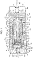
- the opening/closing valve 29 can move along the axial direction of the piston 20 by the above-mentioned distance as shown in Figs.5 (a) and (b), and when the piston 20 is moved in a direction for compressing the refrigerant, the tapered portion 34 of the opening/closing valve 29 abuts against the tapered surface 32 of the piston body 28 to close the through hole 33.
- the rod 22, the piston body 28 and the flange 24 are separately formed as shown in Fig.1, the rod 22 and the piston body 28, or the rod 22 and the flange 24 may be integrally formed.
- the linear motor comprises the movable member 40 and the stationary member 50.
- the movable member 40 comprises a cylindrical holding member 41, a permanent magnet 42 and a cylindrical body 43.
- the stationary member 50 comprises an inner yoke 51, an outer yoke 52 and a coil 53.
- Fig.2 is an enlarged sectional view of an essential portion for explaining the movable member 40 and the stationary member 50.
- All of the cylindrical holding member 41, the permanent magnet 42 and the cylindrical body 43 of the movable member 40 are cylindrical in shape, and are disposed concentrically with the piston 20.
- the cylindrical holding member 41 is thin, and is disposed in a state in which its rear end is in contact with the side surface 24B of the flange 24.
- the cylindrical holding member 41 is fitted to the flange 24 or fixed by fixing means which is not shown. With the above arrangement, the cylindrical holding member 41 is disposed concentrically with the piston 20.
- the permanent magnet 42 is disposed such that it is in contact with the cylindrical holding member 41.
- the cylindrical body 43 is disposed such that it is in contact with the permanent magnet 42.
- the permanent magnet 42 is sandwiched between the cylindrical holding member 41 and the cylindrical body 43.
- the stationary member 50 comprises the inner yoke 51, the outer yoke 52 and the coil 53.
- the inner yoke 51 is cylindrical in shape, and in the present embodiment, the inner yoke 51 is in contact with the cylindrical member 13 of the cylinder 10, and is fixed to the flange portion 11. A fine gap is formed between the outer periphery of the inner yoke 51 and the cylindrical holding member 41.
- the inner yoke 51 is disposed concentrically with the cylinder 10 and the piston 20.
- the outer yoke 52 is also cylindrical in shape, and is disposed such that a fine gap is formed between the outer yoke 52 and the outer periphery of the cylindrical body 43.
- the outer yoke 52 is fixed to the flange portion 11 of the cylinder 10. With the above arrangement, the movable member 40 and the stationary member 50 are held concentrically with each other with high precision.
- the stationary member 50 and the movable member 40 constituting the linear motor are disposed around outer peripheries of the cylinder 10 and the piston 20, respectively, and the piston 20 and the linear motor are not juxtaposed in the moving direction. Therefore, the overall length of the piston 20 and the movable member 40 which become moving members can be shortened as compared with a case in which the piston 20 and the linear motor are juxtaposed in the moving direction, and even if the piston 20 is inclined slightly, the fine gap between the stationary member 50 and the movable member 40 is maintained stably.
- the coil 53 is provided in the outer yoke 52, and is disposed outside the movable member 40.
- the movable member 40 can be reduced in weight.
- the movable member 40 and the stationary member 50 are held concentrically with each other with high precision, the movable member 40 is reduced in weight and therefore, the moving motion can be carried out smoothly. Further, since the permanent magnet 42 is sandwiched and fixed between the cylindrical holding member 41 and the cylindrical body 43, adhesive or setscrew is not used at all. Therefore, mounting operation is facilitated, and the permanent magnet 42 can be held for a long term with high precision.
- Fig.3 shows another embodiment of the cylindrical holding member.
- This cylindrical holding member 41A comprises a flange surface 44 which is integrally formed on the rear end of the cylindrical holding member 41 shown in Fig.2.
- the flange surface 44 is disposed in a direction perpendicular to the axis of the piston 20.
- This cylindrical holding member 41A is held by the side surface 24B and the end surface 24C of the flange 24. That is, like the cylindrical holding member 41, the cylindrical holding member 41A is fitted to the side surface 24B, the flange surface 44 abuts against the end surface 24C, the pushing plate abuts against the flange surface 44, the bolt 27 is fastened, thereby holding the cylindrical holding member 41A strongly by the flange 24 with high precision.
- other constituent elements are the same as those shown in Fig.2.
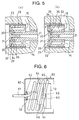
- Fig.4 shows detailed structure of the cylindrical holding member 41.
- the cylindrical holding member 41 is a thin cylindrical body, and the permanent magnet 42 is provided around the cylindrical holding member 41.
- the cylindrical holding member 41 is formed with a large number of slits 45 along the axial direction of the piston 20.
- the cylindrical holding member 41 can prevent eddy current from being generated by these slits 45. It is also effective that the same slits are formed in the cylindrical body 43.
- a discharge valve supporting body 61 is fixed to a front end of the cylinder 10, and a discharge hole 62 is formed in its central portion.
- a discharge valve 63 is provided in the discharge hole 62.
- a muffler 64 is fixed to the valve supporting body 61.
- a base end of a coiled discharge pipe 65 is connected to a discharge port 66 of the muffler 64, and a front end of the coiled discharge pipe 65 is connected to a discharge pipe 67.
- the coiled discharge pipe 65 comprises a pipe which is coiled, and portions thereof are wound around outer peripheral space of the cylinder 10 and the muffler 64.
- the spring mechanism 70 comprises flat spring plates 71 and 72 disposed at rear sides. As shown in Fig.1, the spring plates 71 and 72 are disposed at rear sides of the cylinder 10 and the piston 20 such as to be astride the cylinder 10 and the piston 20.
- the vessel 80 is a cylindrical container comprising a rear end plate 81, a front end plate 82 and a cylindrical barrel body 83 fixed between the rear end plate 81 and the front end plate 82, and a space 84 is formed inside the vessel 80. Constituent elements of the linear compressor are accommodated in the space 84.
- the rear end plate 81 is provided with a suction pipe 85
- the front end plate 82 is provided with a discharge pipe 67.
- the supporting mechanism 90 comprises a rear coil spring 91 and a front coil spring 92.
- the rear coil spring 91 is disposed between an astride plate 93 and the rear end plate 81 of the vessel 80
- the front coil spring 92 is disposed between the muffler 64 and the front end plate 82 of the vessel 80.
- the rear coil spring 91 and the front coil spring 92 are for preventing the vibration transmitted to the cylinder 10 from being transmitted to the vessel 80.
- the refrigerant is introduced into the vessel 80 from the suction pipe 85.
- the refrigerant introduced into the vessel 80 is introduced into the space 14 of the cylinder 10 from the suction port 15 of the cylinder 10.
- the refrigerant is introduced into a suction compressing chamber 68 from a gap generated between the tapered portion 34 of the opening/closing valve 29 and the tapered surface 32 of the piston body 28.
- the refrigerant in the suction compressing chamber 68 is compressed by the advancing motion of the piston 20.
- the compressed refrigerant opens the discharge valve 63, and enters into the muffler 64 through the discharge hole 62 of the discharge valve supporting body 61 where the refrigerant is dispersed and noise thereof is reduced, and the refrigerant is introduced from the discharge port 66 into the coiled discharge pipe 65, and is discharged out from the discharge pipe 67.
- the vibration of the cylinder 10 generated in association with the reciprocating motion of the piston 20 is suppressed by the rear and front coil springs 91 and 92.
- the linear motor is disposed around the outer periphery of the piston 20, and the piston 20 and the linear motor are not juxtaposed in the moving direction. Therefore, the overall length of the moving portion comprising the movable member 40 and the piston 20 is shortened as compared with a case in which the piston 20 and the linear motor are juxtaposed in the moving direction. Therefore, even if the piston 20 is inclined slightly, little influence is exerted on the inclination of the movable member 40. Further, since the movable member 40 is held concentrically with the piston 20, the movable member 40 can smoothly move together with the movement of the piston 20 while keeping the concentric relation therewith. On the other hand, stationary member 50 is fixedly held at the cylinder 10 side, the fine gap between the movable member 40 and the stationary member 50 is little varied, and the piston 20 can move smoothly and efficiently.
- the permanent magnet 42 of the movable member 40 is sandwiched and fixed between the cylindrical holding members 41, 41A and the cylindrical body 43 without using the adhesive or screw, the permanent magnet 42 can easily be mounted, and is always maintained stably. Further, by providing the slits 45 in the cylindrical holding member 42 and the cylindrical body 43, the generation of eddy current is reduced, and the performance is prevented from being lowered.
- linear compressor is as shown in Fig.1, detailed structure thereof should not be limited to the illustrated structure.
- the mounting precision of the piston of the movable member of the linear motor can be enhanced, and the gap between the stationary member and the movable member can always be maintained stably. Therefore, reciprocating motions of the piston and the suction mechanism are smoothly and stably be carried out, and the compression efficiency can be enhanced. Further, the permanent magnet can easily be mounted to the movable member with high precision, and the mounting operation is facilitated.
Landscapes
- Engineering & Computer Science (AREA)
- Mechanical Engineering (AREA)
- General Engineering & Computer Science (AREA)
- Compressors, Vaccum Pumps And Other Relevant Systems (AREA)
- Linear Motors (AREA)
Applications Claiming Priority (2)
| Application Number | Priority Date | Filing Date | Title |
|---|---|---|---|
| JP23949998 | 1998-08-11 | ||
| JP23949998A JP3499447B2 (ja) | 1998-08-11 | 1998-08-11 | リニア圧縮機 |
Publications (2)
| Publication Number | Publication Date |
|---|---|
| EP0979943A2 true EP0979943A2 (de) | 2000-02-16 |
| EP0979943A3 EP0979943A3 (de) | 2001-01-17 |
Family
ID=17045701
Family Applications (1)
| Application Number | Title | Priority Date | Filing Date |
|---|---|---|---|
| EP99115774A Withdrawn EP0979943A3 (de) | 1998-08-11 | 1999-08-10 | Linearkompressor |
Country Status (3)
| Country | Link |
|---|---|
| US (1) | US6250895B1 (de) |
| EP (1) | EP0979943A3 (de) |
| JP (1) | JP3499447B2 (de) |
Cited By (5)
| Publication number | Priority date | Publication date | Assignee | Title |
|---|---|---|---|---|
| EP1167765A3 (de) * | 2000-06-19 | 2003-07-23 | Matsushita Electric Industrial Co., Ltd. | Linearkompressor |
| EP1724466A1 (de) * | 2005-05-06 | 2006-11-22 | Lg Electronics Inc. | Linearverdichter |
| CN103671013A (zh) * | 2013-11-21 | 2014-03-26 | 中国科学院上海技术物理研究所 | 采用短线圈轴向充磁的对置式动圈直线压缩机及制造方法 |
| US9605666B2 (en) | 2000-10-17 | 2017-03-28 | Fisher & Paykel Appliances Limited | Linear compressor |
| EP3699426A1 (de) * | 2019-02-20 | 2020-08-26 | Sumitomo Heavy Industries, Ltd. | Linearverdichter für einen kryokühler |
Families Citing this family (14)
| Publication number | Priority date | Publication date | Assignee | Title |
|---|---|---|---|---|
| US6687122B2 (en) | 2001-08-30 | 2004-02-03 | Sun Microsystems, Inc. | Multiple compressor refrigeration heat sink module for cooling electronic components |
| US6637231B1 (en) | 2002-06-28 | 2003-10-28 | Sun Microsystems, Inc. | Field replaceable packaged refrigeration heat sink module for cooling electronic components |
| KR100511325B1 (ko) * | 2002-12-20 | 2005-08-31 | 엘지전자 주식회사 | 왕복동식 압축기를 구비한 냉동장치 |
| US6741469B1 (en) | 2003-02-07 | 2004-05-25 | Sun Microsystems, Inc. | Refrigeration cooling assisted MEMS-based micro-channel cooling system |
| CN100375838C (zh) * | 2003-05-20 | 2008-03-19 | 乐金电子(天津)电器有限公司 | 活塞式压缩机的压缩装置及其制作方法 |
| US7032400B2 (en) | 2004-03-29 | 2006-04-25 | Hussmann Corporation | Refrigeration unit having a linear compressor |
| JP4770183B2 (ja) * | 2005-01-28 | 2011-09-14 | アイシン精機株式会社 | リニア圧縮機 |
| BRPI0601645B1 (pt) * | 2006-04-18 | 2018-06-05 | Whirlpool S.A. | Compressor linear |
| JP5391706B2 (ja) * | 2009-01-29 | 2014-01-15 | アイシン精機株式会社 | リニア式電磁駆動装置 |
| JP6403529B2 (ja) * | 2014-10-07 | 2018-10-10 | 住友重機械工業株式会社 | 可動体支持構造、リニア圧縮機、及び極低温冷凍機 |
| CN110492714B (zh) * | 2019-08-06 | 2024-09-03 | 包头江馨微电机科技有限公司 | 一种高效散热的音圈电机 |
| JP7762910B2 (ja) * | 2022-02-17 | 2025-10-31 | カヤバ株式会社 | 筒型リニアモータ |
| US12381463B2 (en) * | 2023-02-06 | 2025-08-05 | Attollo Engineering, LLC | Adjustable system to minimize magnetic motor side loads |
| IL318564A (en) * | 2024-01-25 | 2025-08-01 | Attollo Eng Llc | Cut-off bearing for linear compressor |
Citations (3)
| Publication number | Priority date | Publication date | Assignee | Title |
|---|---|---|---|---|
| JPH0434760A (ja) | 1990-05-31 | 1992-02-05 | Sanyo Electric Co Ltd | 回転型のディスクオートチェンジャー装置 |
| JPH08144954A (ja) | 1994-11-17 | 1996-06-04 | Sanyo Electric Co Ltd | ガス圧縮機 |
| US5525845A (en) | 1994-03-21 | 1996-06-11 | Sunpower, Inc. | Fluid bearing with compliant linkage for centering reciprocating bodies |
Family Cites Families (9)
| Publication number | Priority date | Publication date | Assignee | Title |
|---|---|---|---|---|
| NL6617991A (de) | 1966-12-22 | 1968-06-24 | ||
| NL6704284A (de) * | 1967-03-23 | 1968-09-24 | ||
| CH501405A (fr) * | 1968-12-13 | 1971-01-15 | Inst Rech Diffusion Ind | Appareil pour l'obtention d'un jet pulsé pour soins corporels |
| US3910729A (en) * | 1973-06-25 | 1975-10-07 | Air Prod & Chem | Compressor |
| US4644851A (en) | 1984-02-03 | 1987-02-24 | Helix Technology Corporation | Linear motor compressor with clearance seals and gas bearings |
| US5146124A (en) | 1987-10-08 | 1992-09-08 | Helix Technology Corporation | Linear drive motor with flexible coupling |
| IL109267A (en) * | 1993-04-13 | 1998-02-22 | Hughes Aircraft Co | Linear compressor including reciprocating piston and machined double-helix piston spring |
| AU681825B2 (en) * | 1995-05-31 | 1997-09-04 | Sawafuji Electric Co., Ltd. | Vibrating compressor |
| KR100224186B1 (ko) * | 1996-01-16 | 1999-10-15 | 윤종용 | 선형 압축기 |
-
1998
- 1998-08-11 JP JP23949998A patent/JP3499447B2/ja not_active Expired - Fee Related
-
1999
- 1999-08-09 US US09/370,166 patent/US6250895B1/en not_active Expired - Fee Related
- 1999-08-10 EP EP99115774A patent/EP0979943A3/de not_active Withdrawn
Patent Citations (3)
| Publication number | Priority date | Publication date | Assignee | Title |
|---|---|---|---|---|
| JPH0434760A (ja) | 1990-05-31 | 1992-02-05 | Sanyo Electric Co Ltd | 回転型のディスクオートチェンジャー装置 |
| US5525845A (en) | 1994-03-21 | 1996-06-11 | Sunpower, Inc. | Fluid bearing with compliant linkage for centering reciprocating bodies |
| JPH08144954A (ja) | 1994-11-17 | 1996-06-04 | Sanyo Electric Co Ltd | ガス圧縮機 |
Cited By (7)
| Publication number | Priority date | Publication date | Assignee | Title |
|---|---|---|---|---|
| EP1167765A3 (de) * | 2000-06-19 | 2003-07-23 | Matsushita Electric Industrial Co., Ltd. | Linearkompressor |
| US9605666B2 (en) | 2000-10-17 | 2017-03-28 | Fisher & Paykel Appliances Limited | Linear compressor |
| EP1724466A1 (de) * | 2005-05-06 | 2006-11-22 | Lg Electronics Inc. | Linearverdichter |
| US7626289B2 (en) | 2005-05-06 | 2009-12-01 | Lg Electronics Inc. | Linear compressor |
| CN103671013A (zh) * | 2013-11-21 | 2014-03-26 | 中国科学院上海技术物理研究所 | 采用短线圈轴向充磁的对置式动圈直线压缩机及制造方法 |
| CN103671013B (zh) * | 2013-11-21 | 2016-08-24 | 中国科学院上海技术物理研究所 | 采用短线圈轴向充磁的对置式动圈直线压缩机及制造方法 |
| EP3699426A1 (de) * | 2019-02-20 | 2020-08-26 | Sumitomo Heavy Industries, Ltd. | Linearverdichter für einen kryokühler |
Also Published As
| Publication number | Publication date |
|---|---|
| JP2000054957A (ja) | 2000-02-22 |
| JP3499447B2 (ja) | 2004-02-23 |
| US6250895B1 (en) | 2001-06-26 |
| EP0979943A3 (de) | 2001-01-17 |
Similar Documents
| Publication | Publication Date | Title |
|---|---|---|
| US6250895B1 (en) | Linear compressor | |
| EP1503079B1 (de) | Linearkompressor | |
| US6328544B1 (en) | Linear compressor | |
| EP1433955B1 (de) | Linearkompressor | |
| US6506032B2 (en) | Linear compressor | |
| JP3586233B2 (ja) | 往復動式圧縮機のバルブ締結構造 | |
| AU2010269080A1 (en) | Linea compressor | |
| US10876524B2 (en) | Linear compressor | |
| US20090252623A1 (en) | Reciprocating motor and a reciprocating compressor having the same | |
| US6729861B2 (en) | Reciprocating compressor with support springs placed between support members for radial compactness | |
| KR20030096371A (ko) | 선형 모터 및 이 모터를 포함하는 선형 압축기 | |
| CN100416098C (zh) | 往复式压缩机的汽缸支承结构 | |
| JP4055877B2 (ja) | 潤滑油供給装置を有するリニア圧縮機 | |
| JPH09152215A (ja) | リニアモータ式圧縮機 | |
| JP2004190527A (ja) | リニア圧縮機 | |
| JP2000120535A (ja) | リニア圧縮機 | |
| US20070041854A1 (en) | Linear compressor, particularly refrigerant compressor | |
| US20100223936A1 (en) | Linear Compressor with Carbon Fibre Reinforced Spring | |
| JP2003148341A (ja) | リニアモーター式駆動部のリード線取付け構造 | |
| JP2000249054A (ja) | ガス圧縮機 | |
| JP2004019489A (ja) | リニア圧縮機 | |
| CN115750269A (zh) | 一种直线压缩机及制冷机 | |
| AU2006202840B2 (en) | Linear Compressor | |
| JP2006118455A (ja) | 電動モータを駆動源とし、その出力を用いて流体の圧縮を行う圧縮機構を備えた、駆動源及び圧縮機構を備えた圧縮機 | |
| JP2004011495A (ja) | リニア圧縮機 |
Legal Events
| Date | Code | Title | Description |
|---|---|---|---|
| PUAI | Public reference made under article 153(3) epc to a published international application that has entered the european phase |
Free format text: ORIGINAL CODE: 0009012 |
|
| AK | Designated contracting states |
Kind code of ref document: A2 Designated state(s): DE FR |
|
| AX | Request for extension of the european patent |
Free format text: AL;LT;LV;MK;RO;SI |
|
| PUAL | Search report despatched |
Free format text: ORIGINAL CODE: 0009013 |
|
| AK | Designated contracting states |
Kind code of ref document: A3 Designated state(s): AT BE CH CY DE DK ES FI FR GB GR IE IT LI LU MC NL PT SE |
|
| AX | Request for extension of the european patent |
Free format text: AL;LT;LV;MK;RO;SI |
|
| 17P | Request for examination filed |
Effective date: 20010222 |
|
| AKX | Designation fees paid |
Free format text: DE FR |
|
| 17Q | First examination report despatched |
Effective date: 20050316 |
|
| GRAP | Despatch of communication of intention to grant a patent |
Free format text: ORIGINAL CODE: EPIDOSNIGR1 |
|
| STAA | Information on the status of an ep patent application or granted ep patent |
Free format text: STATUS: THE APPLICATION IS DEEMED TO BE WITHDRAWN |
|
| 18D | Application deemed to be withdrawn |
Effective date: 20070814 |