EP0979948B1 - Blattanordnung eines Deckenlüfters - Google Patents
Blattanordnung eines Deckenlüfters Download PDFInfo
- Publication number
- EP0979948B1 EP0979948B1 EP98306361A EP98306361A EP0979948B1 EP 0979948 B1 EP0979948 B1 EP 0979948B1 EP 98306361 A EP98306361 A EP 98306361A EP 98306361 A EP98306361 A EP 98306361A EP 0979948 B1 EP0979948 B1 EP 0979948B1
- Authority
- EP
- European Patent Office
- Prior art keywords
- surface wall
- engaging
- blade assembly
- fan
- mounting
- Prior art date
- Legal status (The legal status is an assumption and is not a legal conclusion. Google has not performed a legal analysis and makes no representation as to the accuracy of the status listed.)
- Expired - Lifetime
Links
- 230000008878 coupling Effects 0.000 claims description 12
- 238000010168 coupling process Methods 0.000 claims description 12
- 238000005859 coupling reaction Methods 0.000 claims description 12
- 230000002093 peripheral effect Effects 0.000 claims description 10
- 238000010276 construction Methods 0.000 description 2
- 230000000717 retained effect Effects 0.000 description 2
- 230000037431 insertion Effects 0.000 description 1
- 238000003780 insertion Methods 0.000 description 1
- 238000002955 isolation Methods 0.000 description 1
- 230000014759 maintenance of location Effects 0.000 description 1
- 239000007769 metal material Substances 0.000 description 1
- 239000000725 suspension Substances 0.000 description 1
Images


Classifications
-
- F—MECHANICAL ENGINEERING; LIGHTING; HEATING; WEAPONS; BLASTING
- F04—POSITIVE - DISPLACEMENT MACHINES FOR LIQUIDS; PUMPS FOR LIQUIDS OR ELASTIC FLUIDS
- F04D—NON-POSITIVE-DISPLACEMENT PUMPS
- F04D25/00—Pumping installations or systems
- F04D25/02—Units comprising pumps and their driving means
- F04D25/08—Units comprising pumps and their driving means the working fluid being air, e.g. for ventilation
- F04D25/088—Ceiling fans
-
- F—MECHANICAL ENGINEERING; LIGHTING; HEATING; WEAPONS; BLASTING
- F04—POSITIVE - DISPLACEMENT MACHINES FOR LIQUIDS; PUMPS FOR LIQUIDS OR ELASTIC FLUIDS
- F04D—NON-POSITIVE-DISPLACEMENT PUMPS
- F04D29/00—Details, component parts, or accessories
- F04D29/26—Rotors specially for elastic fluids
- F04D29/32—Rotors specially for elastic fluids for axial flow pumps
- F04D29/34—Blade mountings
Definitions
- This invention relates to a fan blade assembly of a ceiling fan for mounting on a rotor of a ceiling fan, more particularly to a fan blade assembly which can retain a blade member on a mounting arm effectively and firmly.
- a conventional fan blade assembly is shown to include a mounting arm 10 with one end 11 secured on a rotor (not shown) and the other end formed as a plate-like blade mounting end 13 which has a plurality of through holes 133 and a plurality of engaging posts 131 extending downwardly from the blade mounting end 13 adjacent to the through holes 133.
- a blade member 20 is formed with a plurality of mounting holes 21, each confined by an inner peripheral wall with a constricted portion to divide the mounting hole 21 into a notch portion 211 and a bore portion 212.
- each engaging post 131 can be pressed into the bore portion 212 of the respective mounting hole 21, and can then be moved into the notch portion 211 via the constricted portion such that a retaining portion 132 thereof rests on a bottom side of the blade member 20.
- a cap member 30 has a plurality of resilient engaging plugs 31 with retaining portions 312. Each engaging plug 31 is inserted into and is fitted snugly in the bore portion 212 of the respective mounting hole 21 such that the retaining portion 312 passes through the through hole 133 for retention on the mounting end 13.
- the blade member 20 can be mounted on the mounting arm 10.
- the mounting arm 10 and the cap member 30 are made of metal material and are not produced with high precision, it is difficult to assemble the engaging plugs 31 into the mounting holes 21 and the through holes 133. In addition, a clearance will be caused in each mounting hole 21 between the engaging post 131 and the respective engaging plug 31, thereby resulting in unsteady engagement of the blade member 20 on the mounting arm 10.
- a vibration isolation suspension system for attaching fan blades to the blade supporting arms in a ceiling fan is known from document US-A- 5 304 037.
- the object of the present invention is to provide a fan blade assembly which can retain a blade member on a mounting arm effectively and firmly.
- a fan blade assembly includes a mounting arm with a mounting end which is formed with a plurality of engaging posts.
- a blade member has a plurality of mounting holes, each having a larger bore portion and a smaller notch portion divided by a constricted portion.
- a plurality of elastomeric coupling members are sleeved securely on the engaging posts, and have shanks and radial outward peripheral flanges. Each coupling member is fitted snugly in the notch portion by passing the shank thereinto after the peripheral flange has been brought to pass through the bore portion to rest on one side of the blade member.
- a cap member has a plurality of engaging plugs.
- each engaging plug is inserted into and is fitted snugly in the bore portion of the respective mounting hole in such a manner that a guiding portion thereof will gradually be brought to abut against the constricted portion.
- each engaging plug is further split to form a resilient portion for facilitating insertion of the engaging plug into the bore portion of the respective mounting hole.
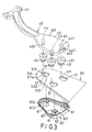
- the first preferred embodiment of a fan blade assembly is shown to comprise a mounting arm 40 which has a connecting end portion 41 adapted for coupling with a rotor of a ceiling fan (not shown), and a plate-like blade mounting end portion 43 with first and second surface walls 431,432 and a plurality of engaging posts 44 protruding downwardly from the second surface wall 432 in a longitudinal direction.
- Each engaging post 44 includes an upper section 441, a lower section 443, and a narrow neck section 442 formed between the upper and lower sections 441,443.
- a blade member 50 has a connecting end which has a third surface wall 501 confronting the second surface wall 432, and an opposite fourth surface wall 502.
- the connecting end further has a plurality of mounting holes 51, each of which is confined by an inner peripheral wall 511 with a constricted portion 511a to divide the mounting hole 51 into a notch portion 513 and a bore portion 512 of a dimension larger than that of the notch portion 513.
- a plurality of elastomeric coupling members 45 are mounted to the connecting end of the blade member 50.
- Each coupling member 45 has a through hole 453 so that the corresponding one of the engaging posts 44 is inserted into and is retainingly engaged in the through hole 453 in such a manner that the lower section 443 hooks on a bottom side of the coupling member 45.
- each coupling member 45 includes a head 451 and a shank 452 which extends downwardly from the head 451 and which has a radial outward peripheral flange 452a.
- a cap member 60 has an upper fifth surface wall 601 which confronts the fourth surface wall 502 and which has a plurality of annular engaging plugs 61 extending upwardly in the longitudinal direction from the fifth surface wall 502.
- Each engaging plug 61 is formed with a distal engaging portion 612, and a proximate engaging portion 613 proximate to the fifth wall surface 601 and provided with an inclined guiding portion 611.
- the engaging plug 61 is split to form a resilient portion 62 at a position opposite to the guiding portion 611.
- the resilient portion 62 has a radially and outwardly extending retaining portion 621 on a top end thereof so as to hook on the third surface wall 501 immediately after the engaging plug 61 has been press-fitted in the bore portion 512 of the respective mounting hole 51 against a biasing action of the retaining portion 621.
- the coupling members 45 are fitted snugly in the notch portions 513, respectively, by passing the shanks 452 thereinto after the peripheral flanges 452a have been brought to pass downwardly through the bore portion 512 to rest on the fourth surface wall 502 of the blade member 50. Subsequently, the engaging plugs 61 are brought to be inserted upwardly into and fitted snugly in the bore portions 512, respectively, so that the guiding portions 611 abut gradually against the constricted portions 511a.
- each engaging plug 61 can be inserted easily into the bore portion 512 of the respective mounting hole 51 due to the provision of the resilient portion 62.
- the engaging plug 61 and the coupling member 45 can be engaged together tightly, thereby preventing the creation of a clearance therebetween in the respective mounting hole 51.
- the blade member 50 can be retained securely on the mounting arm 40.
- the noise due to vibrations when the ceiling fan rotates can be eliminated by virtue of the coupling members 45.
- cap member 60 can be decorated to enhance the aesthetic appeal of the ceiling fan.
- the second preferred embodiment of the fan blade assembly is shown to have a construction similar to that of the first preferred embodiment, except that the first surface wall 431' of the mounting arm 40' is under the second surface wall 432'. That is, the engaging posts 44' extend upwardly from the second surface wall 432'. Likewise, the engaging plugs 61' of the cap member 60'extend downwardly from the fifth surface wall 601' so as to retain the cap member 60' above the blade mounting end portion 43' in a manner similar to that mentioned hereinabove.
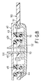
- Figs. 7 and 8 show the third preferred embodiment of this invention, wherein, in addition to the components of the first preferred embodiment, the cap member 70 further has a resilient dog member 72 which extends upwardly in the longitudinal direction from the fifth surface wall 701 among the engaging plugs 71.
- the dog member 72 has a length longer than that of the engaging plugs 71, and a hook end portion 721 so as to hook on the first surface wall 431 immediately after the dog member 72 passes snugly though a through hole 52 in the blade member 50 and a through hole 46 in the blade mounting end portion 43 against a biasing action of the hook end portion 721. As such, the blade member 50 is firmly retained on the mounting arm 40.
- the cap member 80 of the fourth preferred embodiment has a dog member 82 to replace one of the engaging plugs 81. Since the dog member 82 is similar to the dog member 72 in Fig. 7, a detailed description of the construction thereof will be omitted herein.
- the blade mounting end portion 43 is formed with a through hole 47 near one of the engaging posts 44 so that the hook end portion 821 of the dog member 82 can pass through the bore portion 512 of one of the mounting holes 51 and the through hole 47 to hook on the first surface wall 431.
Landscapes
- Engineering & Computer Science (AREA)
- Mechanical Engineering (AREA)
- General Engineering & Computer Science (AREA)
- Structures Of Non-Positive Displacement Pumps (AREA)
Claims (3)
- Eine Blattanordnung eines Lüfters, welche geeignet ist, auf einem Rotor eines Deckenlüfters montiert zu werden, wobei die besagte Blattanordnung eines Lüfters einen Halte- bzw. Tragarm (40, 40') aufweist, welcher einen plattenartigen Endbereich (43, 43') zum Halten bzw. Tragen eines Blatts aufweist mit einer ersten Oberflächenwand (431, 431'), einer zweiten Oberflächenwand (432, 432') und einer Mehrzahl von Eingriffssäulen bzw. zapfen (44, 44'), welche von der besagten zweiten Oberflächenwand (432, 432') in einer Längsrichtung vorstehen;
ein Blattteil (50), welches ein Verbindungsende hat, welches eine dritte Oberflächenwand (501) hat, welche der besagten zweiten Oberflächenwand (432, 432') gegenüber liegt bzw. ihr zugewandt ist und eine vierte Oberflächenwand (502) entgegengesetzt zu der besagten dritten Oberflächenwand (501); und
ein Abdeckkappenteil (60, 60', 70, 80) mit einer fünften Oberflächenwand (601, 601', 701), welche der besagten vierten Oberflächenwand (502) gegenüberliegt bzw. ihr zugewandt ist;
weiter dadurch gekennzeichnet, dass:das besagte Verbindungsende weiter eine Mehrzahl von inneren Umfangswänden (511) aufweist, welche jeweils eine Mehrzahl von Befestigungslöchern (51) umgrenzen, wobei jede der besagten inneren Umfangswände (511) einen eingeschnürten bzw. verengten Bereich (511a) aufweist, um ein entsprechendes der besagten Befestigungslöcher (51) in einen Einschnittbereich (513) und einen Bohrungsbereich (512) von einer größeren Abmessung bzw. Dimension als derjenigen des besagten Einschnittsbereichs (513) zu unterteilen;eine Mehrzahl von elastomerischen Kupplungsteilen (45, 45'), von denen jedes ein Durchgangsloch (453) aufweist, welches durch es hindurch gebildet ist, derart, dass eine entsprechende der besagten Eingriffssäulen bzw. -zapfen (44) in das besagte Durchgangsloch (453) eingesetzt ist und haltend mit ihm in Eingriff ist, wobei die besagten Kupplungsteile (45) einen Schaft (452) und einen radialen äußeren Umfangsflansch (452a) aufweisen, welcher von dem Schaft (452) vorragt und eng bzw. bündig in dem besagten Einschnittsbereich (513) anliegt, indem der besagte Schaft (452) hineingeführt wird, nachdem der besagte Umfangsflansch (452a) dazu gebracht wurde, dass er durch den besagten Bohrungsbereich (512) verläuft, und auf der besagten vierten Oberflächenwand (502) des besagten Blattteils (50) ruht; unddass das besagte Abdeckkappenteil (60, 60', 70, 80) weiterhin eine Mehrzahl von ringförmigen Eingriffszapfen bzw. -dübeln (61, 61', 71, 81) aufweist, von denen sich jeder in der Längsrichtung von der besagten fünften Oberflächenwand (601, 601', 701) erstreckt, um einen entfernten bzw. distalen Eingriffsbereich (612) zu bilden und einen nahen Eingriffsbereich (613) zu bilden, welcher nahe der besagten fünften Oberflächenwand (601, 601', 701) liegt, wobei der entfernte bzw. distale Eingriffsbereich (612) einen Führungsbereich (611) an einer solchen Position aufweist, dass wenn der besagte Eingriffszapfen bzw. - dübel (61, 61', 71, 81) in den besagten Bohrungsbereich (512) von einem jeweiligen der besagten Befestigungslöcher (51) eingeführt wird und darin eng bzw. bündig sitzt, der besagte Führüngsbereich (611) graduell gegen den besagten verengten bzw. eingeschnürten Bereich (511a) anstößt bzw. angrenzt. - Die Blattanordnung eines Lüfters wie in Anspruch 1 beansprucht, dadurch gekennzeichnet, dass jeder der besagten Eingriffszapfen bzw. -dübel (61, 61'. 71, 81) gespalten ist, um einen federnden Bereich (62) mit einem sich radial und nach außen erstreckenden rückhaltenden Bereich (621) zu bilden, welcher an der besagten dritten Oberflächenwand (501) des besagten Blattteils (50) einhakt, unmittelbar nachdem jeder der besagten Eingriffszapfen bzw. -dübel (61, 61', 71, 81) unter Presspassung bzw. Presssitz in den besagten Bohrungsbereich (512) des jeweiligen der besagten Montage- oder Befestigungslöcher (51) gegen eine Vorspannungswirkung des besagten Rückhaltebereichs (621) eingedrückt worden ist.
- Die Blattanordnung eines Lüfters, wie in Anspruch 1 oder 2 beansprucht, weiterhin gekennzeichnet durch ein federndes Klauenteil (72, 82), welches auf dem besagten Abdeckkappenteil (70, 80) gebildet ist und sich in der Längsrichtung von der besagten fünften Oberflächenwand (701) erstreckt, wobei das Klauenteil (72, 82) eine Länge länger als diejenige der besagten Eingriffszapfen bzw. -dübel (71, 81) besitzt und einen hakenförmigen Endbereich (721, 821) besitzt, welcher an der besagten ersten Oberflächenwand (431) einhakt, unmittelbar nachdem das besagte Klauenteil (72, 82) dazu gebracht ist, dass es eng anliegend bzw. eng passend durch das besagte Blattteil (50) verläuft und der Endbereich (43) zur Befestigung des Blatts gegen eine vorspannende Wirkung des besagten Hakenendbereichs (721, 821) gedrückt ist.
Priority Applications (4)
| Application Number | Priority Date | Filing Date | Title |
|---|---|---|---|
| EP98306361A EP0979948B1 (de) | 1998-08-10 | 1998-08-10 | Blattanordnung eines Deckenlüfters |
| DE69816071T DE69816071T2 (de) | 1998-08-10 | 1998-08-10 | Blattanordnung eines Deckenlüfters |
| US09/176,727 US6039540A (en) | 1998-08-10 | 1998-10-21 | Fan blade assembly of a ceiling fan |
| CA002274160A CA2274160A1 (en) | 1998-08-10 | 1999-06-10 | Fan blade assembly of a ceiling fan |
Applications Claiming Priority (3)
| Application Number | Priority Date | Filing Date | Title |
|---|---|---|---|
| EP98306361A EP0979948B1 (de) | 1998-08-10 | 1998-08-10 | Blattanordnung eines Deckenlüfters |
| US09/176,727 US6039540A (en) | 1998-08-10 | 1998-10-21 | Fan blade assembly of a ceiling fan |
| CA002274160A CA2274160A1 (en) | 1998-08-10 | 1999-06-10 | Fan blade assembly of a ceiling fan |
Publications (2)
| Publication Number | Publication Date |
|---|---|
| EP0979948A1 EP0979948A1 (de) | 2000-02-16 |
| EP0979948B1 true EP0979948B1 (de) | 2003-07-02 |
Family
ID=32329379
Family Applications (1)
| Application Number | Title | Priority Date | Filing Date |
|---|---|---|---|
| EP98306361A Expired - Lifetime EP0979948B1 (de) | 1998-08-10 | 1998-08-10 | Blattanordnung eines Deckenlüfters |
Country Status (4)
| Country | Link |
|---|---|
| US (1) | US6039540A (de) |
| EP (1) | EP0979948B1 (de) |
| CA (1) | CA2274160A1 (de) |
| DE (1) | DE69816071T2 (de) |
Families Citing this family (43)
| Publication number | Priority date | Publication date | Assignee | Title |
|---|---|---|---|---|
| US6210117B1 (en) | 1999-09-03 | 2001-04-03 | King Of Fans, Inc. | Device for connecting a fan blade to a rotor of a ceiling fan motor |
| US6352411B1 (en) | 1997-05-05 | 2002-03-05 | King Of Fans, Inc. | Quick install blade arms for ceiling fans |
| US7281899B1 (en) | 1997-05-05 | 2007-10-16 | King Of Frans, Inc. | Quick assembly blades for ceiling fans |
| US6666652B2 (en) * | 1997-05-05 | 2003-12-23 | King Of Fans, Inc. | Slide in, hook and fold out ceiling fan blades |
| US6309183B1 (en) * | 1997-05-05 | 2001-10-30 | King Of Fans, Inc. | Blade arm |
| US6688850B2 (en) | 1997-05-05 | 2004-02-10 | King Of Fans, Inc. | Hook and fold ceiling fan blades |
| US6872053B2 (en) * | 1997-05-05 | 2005-03-29 | King Of Fans | Quick install blade arms for ceiling fans |
| US6010306A (en) | 1997-05-05 | 2000-01-04 | King Of Fans, Inc. | Quick assembly blades for ceiling fans |
| US5951197A (en) | 1998-11-17 | 1999-09-14 | Wu; San-Chi | Connecting device for connecting a fan blade to a rotor of a motor of a ceiling fan |
| CN2412115Y (zh) * | 1999-11-12 | 2000-12-27 | 蚬壳电器工业(集团)有限公司 | 吊扇扇叶的固定机构 |
| US6213716B1 (en) | 1999-11-19 | 2001-04-10 | King Of Fans, Inc. | Folding fan |
| US6585488B1 (en) * | 2000-02-25 | 2003-07-01 | King Of Fans, Inc. | Ceiling fan blade isolation system |
| US6508629B2 (en) * | 2001-03-06 | 2003-01-21 | Angelo Fan Brace Licensing, L.L.C. | Connector for attaching a ceiling fan blade to a fan blade holder |
| US6652236B2 (en) | 2001-11-29 | 2003-11-25 | Hoo Cheung Group Ltd. | Fan blade assembly and method of assembling |
| US6821091B2 (en) | 2002-06-05 | 2004-11-23 | Litex Industries Inc. | Securing device |
| US6863499B2 (en) * | 2002-07-12 | 2005-03-08 | Hunter Fan Company | Quick connect blade iron system |
| US6840739B2 (en) * | 2003-02-04 | 2005-01-11 | Hunter Fan Company | Ceiling fan |
| US6932576B2 (en) * | 2003-04-01 | 2005-08-23 | Hunter Fan Company | Quick connect ceiling fan blade |
| US6902374B2 (en) * | 2003-04-15 | 2005-06-07 | Hunter Fan Company | Ceiling fan |
| US6902375B2 (en) * | 2003-05-01 | 2005-06-07 | Hunter Fan Company | Quick connect ceiling fan blade |
| CA2527504A1 (en) * | 2003-06-03 | 2005-04-07 | King Of Fans, Inc. | Slide in hook and fold out ceiling fan blades |
| FR2866930B1 (fr) * | 2004-03-01 | 2008-02-15 | Leroy Somer Moteurs | Ventilateur comportant au moins une pale fixee par bride et contre-bride |
| US7223078B1 (en) | 2004-11-18 | 2007-05-29 | Litex Industries, Limited, Having A General Partner Of Libco International, Llc | Rotary plate fastener for ceiling fan blades |
| US20060140770A1 (en) * | 2004-12-28 | 2006-06-29 | Pan Air Electric Co., Ltd. | Fan blade mounting structure for ceiling fan |
| US7527478B2 (en) * | 2006-05-19 | 2009-05-05 | Hunter Fan Company | Fan blade mounting system |
| US8047795B2 (en) * | 2007-01-18 | 2011-11-01 | Hunter Fan Company | Fan blade mounting system |
| US8356979B2 (en) * | 2008-10-28 | 2013-01-22 | Hunter Fan Company | Fan blade mounting system |
| US8727732B2 (en) * | 2009-11-18 | 2014-05-20 | Hunter Fan Company | Fan blade mounting system |
| CN102062122B (zh) * | 2009-11-18 | 2015-11-25 | 亨特风扇公司 | 风扇叶片安装系统 |
| US20110158812A1 (en) * | 2009-12-31 | 2011-06-30 | New Century Electrical Manufacturing (Zhongshan) Co., Ltd. | Kind of fan blade can be easily assembled and disassembled |
| US9039377B2 (en) | 2010-08-09 | 2015-05-26 | Lowe's Companies, Inc. | Fan assemblies and methods for assembling same |
| USD707346S1 (en) * | 2012-10-25 | 2014-06-17 | Air Cool Industrial Co., Ltd. | Fan blade iron |
| USD707809S1 (en) * | 2012-11-16 | 2014-06-24 | Air Cool Industrial Co., Ltd. | Fan blade iron |
| US9651058B1 (en) | 2013-07-05 | 2017-05-16 | Litex Industries, Limited | T-shaped fan blade arm attachment |
| WO2015179781A1 (en) | 2014-05-23 | 2015-11-26 | Chien Luen Industries Co., Ltd., Inc. | Slide on flush mount bracket with captive fasteners |
| USD787038S1 (en) * | 2015-08-27 | 2017-05-16 | Hunter Fan Company | Blade iron arm for a ceiling fan |
| USD872250S1 (en) * | 2017-11-03 | 2020-01-07 | Hunter Fan Company | Ceiling fan |
| CN108266394A (zh) * | 2018-03-03 | 2018-07-10 | 尹传亮 | 一种隐形的吊扇灯 |
| US11732724B2 (en) * | 2019-12-23 | 2023-08-22 | Hunter Fan Company | Ceiling fan blade and grommet |
| CN113669298A (zh) * | 2021-09-22 | 2021-11-19 | 新盛世机电制品(中山)有限公司 | 一种便于叶叉与叶片快速安装的连接结构 |
| US11959490B2 (en) | 2022-03-29 | 2024-04-16 | Hunter Fan Company | Ceiling fan with a blade connection assembly |
| US11939989B2 (en) * | 2022-04-06 | 2024-03-26 | Hunter Fan Company | Ceiling fan, blade, and blade connector |
| WO2025250458A1 (en) * | 2024-05-25 | 2025-12-04 | Delta T, Llc | Blade retention system for fan and related methods |
Family Cites Families (7)
| Publication number | Priority date | Publication date | Assignee | Title |
|---|---|---|---|---|
| GB2288853B (en) * | 1992-01-29 | 1996-05-08 | Hunter Fan Co | Ceiling fan |
| US5304037A (en) * | 1993-04-14 | 1994-04-19 | Hunter Fan Company | Ceiling fan blade vibration isolation system |
| US5464323A (en) * | 1994-03-02 | 1995-11-07 | Hunter Fan Company | Vibration isolation system for fan blade |
| US5899663A (en) * | 1996-08-07 | 1999-05-04 | Hunter Fan Company | Modular ceiling fan assembly and system |
| US5722814A (en) * | 1997-04-03 | 1998-03-03 | Yu; Chai-Chi | Fan blade mounting device having a decorative member provided thereon |
| US5944486A (en) * | 1997-04-24 | 1999-08-31 | Hodgkins, Jr.; Donald P. | Interchangeable fan blade system |
| US5951197A (en) * | 1998-11-17 | 1999-09-14 | Wu; San-Chi | Connecting device for connecting a fan blade to a rotor of a motor of a ceiling fan |
-
1998
- 1998-08-10 DE DE69816071T patent/DE69816071T2/de not_active Expired - Fee Related
- 1998-08-10 EP EP98306361A patent/EP0979948B1/de not_active Expired - Lifetime
- 1998-10-21 US US09/176,727 patent/US6039540A/en not_active Expired - Lifetime
-
1999
- 1999-06-10 CA CA002274160A patent/CA2274160A1/en not_active Abandoned
Also Published As
| Publication number | Publication date |
|---|---|
| DE69816071T2 (de) | 2004-04-22 |
| EP0979948A1 (de) | 2000-02-16 |
| US6039540A (en) | 2000-03-21 |
| DE69816071D1 (de) | 2003-08-07 |
| CA2274160A1 (en) | 2000-12-10 |
Similar Documents
| Publication | Publication Date | Title |
|---|---|---|
| EP0979948B1 (de) | Blattanordnung eines Deckenlüfters | |
| CA2274156C (en) | Connecting device for connecting a fan blade to a rotor of a motor of a ceiling fan | |
| US6688826B2 (en) | Captive fastener system and retention member | |
| US5954449A (en) | Connecting device for connecting a fan blade to a rotor of a motor of a ceiling fan | |
| KR20200087094A (ko) | 트리형 체결구 제거 조립체 및 그 방법 | |
| EP0979949A1 (de) | Blattanordnung eines Deckenlüfters | |
| JPS6035632Y2 (ja) | 杭引抜具 | |
| JPH0129724Y2 (de) | ||
| JPH0416012Y2 (de) | ||
| JPH032004Y2 (de) | ||
| KR200330464Y1 (ko) | 앵커 조립체 | |
| JPH11280726A (ja) | 抜け止めクリップ | |
| JP2515100Y2 (ja) | ホイールキャップ | |
| JP2002070827A (ja) | プッシュナット | |
| JP2026509529A (ja) | 取付け機構 | |
| JPH0135925Y2 (de) | ||
| JP3930270B2 (ja) | 枠材の組み付け方法および組み付け締結構造 | |
| KR100357419B1 (ko) | 제한된 공간에서의 부품설치방법 및 그 구조 | |
| JPH0223919U (de) | ||
| JPH0712136A (ja) | 円筒ブッシュ組立体 | |
| KR960005194Y1 (ko) | 필기구의 클립부착장치 | |
| JPH0140303Y2 (de) | ||
| JPS5927193Y2 (ja) | カ−テンランナ− | |
| JPH1151024A (ja) | 締結部材 | |
| KR19990037609U (ko) | 걸림장치 |
Legal Events
| Date | Code | Title | Description |
|---|---|---|---|
| PUAI | Public reference made under article 153(3) epc to a published international application that has entered the european phase |
Free format text: ORIGINAL CODE: 0009012 |
|
| AK | Designated contracting states |
Kind code of ref document: A1 Designated state(s): DE FR GB IT NL |
|
| AX | Request for extension of the european patent |
Free format text: AL;LT;LV;MK;RO;SI |
|
| 17P | Request for examination filed |
Effective date: 20000713 |
|
| AKX | Designation fees paid |
Free format text: DE FR GB IT NL |
|
| RBV | Designated contracting states (corrected) |
Designated state(s): DE FR GB IT NL |
|
| GRAH | Despatch of communication of intention to grant a patent |
Free format text: ORIGINAL CODE: EPIDOS IGRA |
|
| GRAH | Despatch of communication of intention to grant a patent |
Free format text: ORIGINAL CODE: EPIDOS IGRA |
|
| GRAA | (expected) grant |
Free format text: ORIGINAL CODE: 0009210 |
|
| AK | Designated contracting states |
Designated state(s): DE FR GB IT NL |
|
| REG | Reference to a national code |
Ref country code: GB Ref legal event code: FG4D |
|
| REF | Corresponds to: |
Ref document number: 69816071 Country of ref document: DE Date of ref document: 20030807 Kind code of ref document: P |
|
| ET | Fr: translation filed | ||
| PLBE | No opposition filed within time limit |
Free format text: ORIGINAL CODE: 0009261 |
|
| STAA | Information on the status of an ep patent application or granted ep patent |
Free format text: STATUS: NO OPPOSITION FILED WITHIN TIME LIMIT |
|
| 26N | No opposition filed |
Effective date: 20040405 |
|
| PGFP | Annual fee paid to national office [announced via postgrant information from national office to epo] |
Ref country code: GB Payment date: 20040804 Year of fee payment: 7 |
|
| PGFP | Annual fee paid to national office [announced via postgrant information from national office to epo] |
Ref country code: FR Payment date: 20040819 Year of fee payment: 7 |
|
| PGFP | Annual fee paid to national office [announced via postgrant information from national office to epo] |
Ref country code: NL Payment date: 20040831 Year of fee payment: 7 |
|
| PGFP | Annual fee paid to national office [announced via postgrant information from national office to epo] |
Ref country code: DE Payment date: 20040930 Year of fee payment: 7 |
|
| PG25 | Lapsed in a contracting state [announced via postgrant information from national office to epo] |
Ref country code: IT Free format text: LAPSE BECAUSE OF NON-PAYMENT OF DUE FEES;WARNING: LAPSES OF ITALIAN PATENTS WITH EFFECTIVE DATE BEFORE 2007 MAY HAVE OCCURRED AT ANY TIME BEFORE 2007. THE CORRECT EFFECTIVE DATE MAY BE DIFFERENT FROM THE ONE RECORDED. Effective date: 20050810 Ref country code: GB Free format text: LAPSE BECAUSE OF NON-PAYMENT OF DUE FEES Effective date: 20050810 |
|
| PG25 | Lapsed in a contracting state [announced via postgrant information from national office to epo] |
Ref country code: NL Free format text: LAPSE BECAUSE OF NON-PAYMENT OF DUE FEES Effective date: 20060301 Ref country code: DE Free format text: LAPSE BECAUSE OF NON-PAYMENT OF DUE FEES Effective date: 20060301 |
|
| GBPC | Gb: european patent ceased through non-payment of renewal fee |
Effective date: 20050810 |
|
| PG25 | Lapsed in a contracting state [announced via postgrant information from national office to epo] |
Ref country code: FR Free format text: LAPSE BECAUSE OF NON-PAYMENT OF DUE FEES Effective date: 20060428 |
|
| NLV4 | Nl: lapsed or anulled due to non-payment of the annual fee |
Effective date: 20060301 |
|
| REG | Reference to a national code |
Ref country code: FR Ref legal event code: ST Effective date: 20060428 |