EP0979986A2 - Pistole, deren Gehaüse aus Kunststoff besteht - Google Patents
Pistole, deren Gehaüse aus Kunststoff besteht Download PDFInfo
- Publication number
- EP0979986A2 EP0979986A2 EP99890257A EP99890257A EP0979986A2 EP 0979986 A2 EP0979986 A2 EP 0979986A2 EP 99890257 A EP99890257 A EP 99890257A EP 99890257 A EP99890257 A EP 99890257A EP 0979986 A2 EP0979986 A2 EP 0979986A2
- Authority
- EP
- European Patent Office
- Prior art keywords
- housing
- barrel
- multifunction
- parts
- trigger mechanism
- Prior art date
- Legal status (The legal status is an assumption and is not a legal conclusion. Google has not performed a legal analysis and makes no representation as to the accuracy of the status listed.)
- Granted
Links
- 229920003023 plastic Polymers 0.000 title claims abstract description 12
- 239000004033 plastic Substances 0.000 title claims abstract description 12
- 239000002184 metal Substances 0.000 claims description 6
- 238000005516 engineering process Methods 0.000 description 2
- 238000013459 approach Methods 0.000 description 1
- 238000010276 construction Methods 0.000 description 1
- 238000002347 injection Methods 0.000 description 1
- 239000007924 injection Substances 0.000 description 1
- 238000001746 injection moulding Methods 0.000 description 1
- 238000005495 investment casting Methods 0.000 description 1
- 238000004519 manufacturing process Methods 0.000 description 1
- 239000000463 material Substances 0.000 description 1
- 238000003466 welding Methods 0.000 description 1
Images

Classifications
-
- F—MECHANICAL ENGINEERING; LIGHTING; HEATING; WEAPONS; BLASTING
- F41—WEAPONS
- F41A—FUNCTIONAL FEATURES OR DETAILS COMMON TO BOTH SMALLARMS AND ORDNANCE, e.g. CANNONS; MOUNTINGS FOR SMALLARMS OR ORDNANCE
- F41A3/00—Breech mechanisms, e.g. locks
- F41A3/64—Mounting of breech-blocks; Accessories for breech-blocks or breech-block mountings
- F41A3/66—Breech housings or frames; Receivers
Definitions
- the invention relates to a pistol consisting of a plastic housing, a a barrel and a breech containing longitudinally with respect to the housing guided carriage and a trigger mechanism. So are Guns of various systems affected.
- Such a pistol is known from practice, GLOCK model 17.
- the carriage guides are single molded parts.
- the manufacture of such Plastic parts are expensive and complicated, the metal parts have to be dimensionally accurate and corrected for shrinkage in the injection mold.
- the bearings for the parts of the trigger mechanism and the control parts for locking the barrel Inserted individually into the housing in modules, resulting in further dimensional deviations to each other and to the slide guides.
- the entire housing must be replaced.
- the individual parts in the housing because poor accessibility inside which are difficult to install. This Disadvantage occurs regardless of the choice of material.
- this is achieved in that a single one in the housing Metal existing multifunctional part is used removably, on which the Guides for the carriage are formed and in which the elements of the trigger mechanism stored or guided.
- the multifunctional part can be easily manufactured and processed with high precision be equipped with all moving parts and only then in the housing used. It can be removed again for repair purposes. On Mondays and repair, all parts are easily accessible. This makes the position of the functionally essential Parts determined much more precisely to each other and also by expansion differences much less affected. Overall, higher precision lower costs achieved.
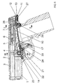
- the gun shown in Fig. 1, 2 and 3 consists of a plastic housing 1 and a on this in the weft direction sliding carriage 2, the one run 3 with control approaches 4, a closure 5, a striker 6 with striker flag 7 and guides 8 includes.
- a tap can also be provided his.
- the entire housing 1 is made of plastic.
- a metallic multifunctional part 10 for this he has behind an extension 11 which in a corresponding recess 13 in the Rear wall 12 engages.
- two such extensions 11 are provided side by side.
- a dismantling lever shaft 14 (FIG. 3) is inserted in bores 15 of the multifunction part 10 and in holes 16 in the side parts of the plastic housing 1.
- the extensions 11 and the disassembling shaft 14 hold the multifunction part in the housing 1.
- the multi-function part 10 can after pulling the disassembly lever shaft 14 and Pulling the extensions 11 out of the recesses 13 removed from the housing 1 become.
- a locking catch lever can also be used 17 be stored.
- a tongue 20 is mounted in a bearing pin 21 which is in the multifunction part 10 plugged.
- the spring of a trigger safeguard 22 is supported on a pin 23.
- Another moving part (such as another fuse) in another pin 24.
- These pins 23,24,25 are also fixed in the multifunction part.
- another guide 27 is formed for a stud lever 26. Consequently are all moving parts of the trigger device with the multifunction part 10 connected. As a result, all these parts can first be attached to the multifunction part 10 and the complete unit is only inserted into the housing 1 at the end.
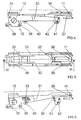
- the multifunction part 10 is shown without accessories. It exists from a right and left side part 30,31, which are interconnected via a first bridge 32, a second bridge 33, which are also control means for locking of barrel 3, and behind by a third bridge 36.
- the side parts 30,31 each carry a front guide 34 and a rear guide on their upper edges 35 for the carriage 2, which engages in this with its guides 8.
- the two extensions 11 are formed at the rear.
- the front Part of the multifunction part 10 is the bore 15 for the disassembly lever shaft 14.
- various holes are provided in both side parts 30.31 a bore 38 for the bearing pin 21, a bore 39 for the pin 23, a bore 40 for the further pin 24 in the front part, as well as in the rear part Bore 41 for the pivot pin 25 and a bore 42 for another part the trigger mechanism.
- the holes 41, 42 and the guide 27 relate to in the training shown a trigger device according to the AT-GM application 477/98.
- the multifunction part 10 can be manufactured in various ways, from milled in full, from investment casting, by welding individual parts or even as a stamped sheet metal part.
Landscapes
- Engineering & Computer Science (AREA)
- General Engineering & Computer Science (AREA)
- Toys (AREA)
- Coating Apparatus (AREA)
Abstract
Description
Claims (4)
- Pistole bestehend aus einem Gehäuse aus Kunststoff, einem einen Lauf und einen Verschluß enthaltenden bezüglich des Gehäuses in Längsrichtung geführten Laufschlitten und einem Abzugsmechanismus, dadurch gekennzeichnet, daß in das Gehäuse (1) ein einziger aus Metall bestehender Multifunktionsteil (10) herausnehmbar eingesetzt ist, an dem die Führungen (34,35) für den Laufschlitten (2) ausgebildet sind und in dem die Elemente (20,22,26) des Abzugsmechanismus gelagert bzw geführt sind.
- Pistole nach Anspruch 1 mit einer quer im Gehäuse gelagerten Zerleghebelwelle (14), dadurch gekennzeichnet, daß der Multifunktionsteil (10) eine Bohrung (15) aufweist, die die Zerleghebelwelle (14) aufnimmt und so die Verbindung zwischen Gehäuse (1) und Multifunktionsteil (10) herstellt.
- Pistole nach Anspruch 1, dadurch gekennzeichnet, daß in der Rückwand (12) des Gehäuses (1) eine Ausnehmung (13) für einen Fortsatz (11) des Multifunktionsteiles (10) vorgesehen ist.
- Pistole nach Anspruch 1 mit einem im Laufschlitten verriegelbaren Lauf, dadurch gekennzeichnet, daß am Multifunktionsteil (10) die Steuermittel (33) für die Verriegelung ausgebildet sind.
Priority Applications (2)
| Application Number | Priority Date | Filing Date | Title |
|---|---|---|---|
| AT99890257T ATE254752T1 (de) | 1998-08-13 | 1999-08-04 | Pistole, deren gehaüse aus kunststoff besteht |
| DE29924790U DE29924790U1 (de) | 1998-08-13 | 1999-08-04 | Pistole, deren Gehäuse aus Kunststoff besteht |
Applications Claiming Priority (2)
| Application Number | Priority Date | Filing Date | Title |
|---|---|---|---|
| AT0053298U AT3456U1 (de) | 1998-08-13 | 1998-08-13 | Pistole, deren gehäuse aus kunststoff besteht |
| AT53298U | 1998-08-13 |
Publications (4)
| Publication Number | Publication Date |
|---|---|
| EP0979986A2 true EP0979986A2 (de) | 2000-02-16 |
| EP0979986A3 EP0979986A3 (de) | 2000-10-11 |
| EP0979986B1 EP0979986B1 (de) | 2003-11-19 |
| EP0979986B2 EP0979986B2 (de) | 2007-07-04 |
Family
ID=3493124
Family Applications (1)
| Application Number | Title | Priority Date | Filing Date |
|---|---|---|---|
| EP99890257A Expired - Lifetime EP0979986B2 (de) | 1998-08-13 | 1999-08-04 | Pistole, deren Gehaüse aus Kunststoff besteht |
Country Status (6)
| Country | Link |
|---|---|
| US (1) | US6260301B1 (de) |
| EP (1) | EP0979986B2 (de) |
| AT (1) | AT3456U1 (de) |
| BR (1) | BR9903590A (de) |
| CZ (1) | CZ293580B6 (de) |
| DE (1) | DE59907781D1 (de) |
Cited By (5)
| Publication number | Priority date | Publication date | Assignee | Title |
|---|---|---|---|---|
| EP1031811A3 (de) * | 1999-02-23 | 2000-10-11 | SIG Arms International AG | Pistole mit einer demontierbaren Struktureinheit |
| EP1870660A1 (de) | 2006-06-23 | 2007-12-26 | S.A.T. Swiss Arms Technology AG | Griffstück für eine Handfeuerwaffe |
| AT513144A4 (de) * | 2013-01-09 | 2014-02-15 | Steyr Mannlicher Gmbh | Feuerwaffe und Gehäuse hiefür |
| EP3809091A1 (de) * | 2019-10-14 | 2021-04-21 | FN Herstal SA | Pistole mit optimierter chassisverankerung |
| WO2021073962A1 (fr) * | 2019-10-14 | 2021-04-22 | Fn Herstal S.A. | Pistolet avec ancrage de chassis optimise |
Families Citing this family (23)
| Publication number | Priority date | Publication date | Assignee | Title |
|---|---|---|---|---|
| US6571500B2 (en) * | 2000-11-15 | 2003-06-03 | Terence J. Keenan | Dry-fire training pistol |
| US6401379B1 (en) * | 2000-11-28 | 2002-06-11 | Kook-Jin Moon | Handgun having a polymer frame |
| DE10108710B4 (de) * | 2001-02-23 | 2011-01-20 | Umarex Sportwaffen Gmbh & Co Kg | Handfeuerwaffe |
| DE10326842B3 (de) * | 2003-06-14 | 2004-12-16 | S.A.T. Swiss Arms Technology Ag | Verschluss für eine Faustfeuerwaffe |
| US7694449B1 (en) * | 2004-02-25 | 2010-04-13 | Pontillo Ii James V | Plastic pistols |
| US20090071053A1 (en) * | 2007-08-30 | 2009-03-19 | Thomele Adrian J O | Modular Firearm System with Interchangeable Grip and Slide Assemblies and an Improved Firing Pin Safety for Firearm |
| AT10398U1 (de) * | 2007-12-21 | 2009-02-15 | Caracal Internat L L C | Waffe, insbesondere handfeuerwaffe |
| RU2439459C1 (ru) * | 2010-04-29 | 2012-01-10 | ООО Производственно-коммерческое предприятие "Агентство коммерческой безопасности, специзделия" (ООО ПКП "АКБС") | Пистолет под патрон травматического действия |
| AT510442B1 (de) | 2011-08-24 | 2012-04-15 | Wilhelm Bubits | Pistole mit verriegelung durch verriegelungskörper |
| US8528243B1 (en) * | 2012-07-10 | 2013-09-10 | Gaston Glock | Pistols and methods of manufacture |
| AT516033B1 (de) * | 2015-02-09 | 2016-02-15 | Wilhelm Bubits | Pistole mit Verriegelungsblock |
| US10317159B2 (en) | 2015-12-28 | 2019-06-11 | Sturm, Ruger & Company, Inc. | Variable barrel camming system for firearm |
| US10119777B2 (en) | 2016-01-18 | 2018-11-06 | ZEV Technologies, Inc. | Modular handgun |
| US10254059B1 (en) | 2017-10-02 | 2019-04-09 | Franklin Armory Holdings, Inc. | Pistol with frame insert |
| US12480740B2 (en) | 2017-12-27 | 2025-11-25 | Magpul Industries Corp. | Two-part folding trigger for a folding firearm |
| WO2019133450A1 (en) | 2017-12-27 | 2019-07-04 | Magpul Industries Corp. | Foldable firearm |
| US12117255B1 (en) | 2018-07-10 | 2024-10-15 | James J. Rofkahr, Jr. | Trigger energy absorption apparatus and method |
| US11385010B1 (en) | 2018-07-10 | 2022-07-12 | James J. Rofkahr, Jr. | Trigger energy absorption apparatus and method |
| US10775122B1 (en) | 2018-07-10 | 2020-09-15 | James J. Rofkahr, Jr. | Trigger energy absorption apparatus and method |
| RU2740108C1 (ru) * | 2020-09-08 | 2021-01-11 | Общество с ограниченной ответственностью Производственно-коммерческое предприятие "АКБС" | Пистолет |
| USD1069016S1 (en) | 2021-06-02 | 2025-04-01 | Magpul Industries Corp. | Folding gun |
| USD1085314S1 (en) | 2021-12-20 | 2025-07-22 | Magpul Industries Corp. | Folding gun |
| US12455126B2 (en) | 2023-12-11 | 2025-10-28 | Icarus Precision Llc | Modular frame and chassis system for a firearm |
Family Cites Families (6)
| Publication number | Priority date | Publication date | Assignee | Title |
|---|---|---|---|---|
| EP0025343A3 (de) * | 1979-09-07 | 1981-09-23 | Anthony Charles Blackshaw | Konstruktionskonzept einer Handfeuerwaffe |
| US4601124A (en) * | 1983-01-31 | 1986-07-22 | Sturm, Ruger & Company, Inc. | Apparatus for increasing the rigidity of a rifle action receiver |
| DE3714464A1 (de) * | 1987-04-30 | 1988-11-10 | Hans Ulrich Dipl Ing Baun | Grosskaliber-pistole (faustfeuerwaffe) fuer das sportliche und "praktische" pistolenschiessen |
| US5293708A (en) * | 1992-07-08 | 1994-03-15 | Strayer Sandy L | Frame/handgrip assembly for autoloading handgun |
| DE9304489U1 (de) * | 1993-03-24 | 1993-08-12 | Heckler & Koch Gmbh, 78727 Oberndorf | Sturmgewehr |
| US5669169A (en) * | 1996-04-16 | 1997-09-23 | Fn Manufacturing, Inc. | Handgun having metallic rails within a polymeric frame |
-
1998
- 1998-08-13 AT AT0053298U patent/AT3456U1/de not_active IP Right Cessation
-
1999
- 1999-08-04 EP EP99890257A patent/EP0979986B2/de not_active Expired - Lifetime
- 1999-08-04 DE DE59907781T patent/DE59907781D1/de not_active Expired - Lifetime
- 1999-08-04 CZ CZ19992777A patent/CZ293580B6/cs not_active IP Right Cessation
- 1999-08-13 US US09/373,671 patent/US6260301B1/en not_active Expired - Lifetime
- 1999-08-13 BR BR9903590-1A patent/BR9903590A/pt not_active IP Right Cessation
Non-Patent Citations (1)
| Title |
|---|
| None |
Cited By (8)
| Publication number | Priority date | Publication date | Assignee | Title |
|---|---|---|---|---|
| EP1031811A3 (de) * | 1999-02-23 | 2000-10-11 | SIG Arms International AG | Pistole mit einer demontierbaren Struktureinheit |
| US6234059B1 (en) | 1999-02-23 | 2001-05-22 | Sig Arms International Ag | Pistol including a removable structural unit |
| EP1870660A1 (de) | 2006-06-23 | 2007-12-26 | S.A.T. Swiss Arms Technology AG | Griffstück für eine Handfeuerwaffe |
| AT513144A4 (de) * | 2013-01-09 | 2014-02-15 | Steyr Mannlicher Gmbh | Feuerwaffe und Gehäuse hiefür |
| AT513144B1 (de) * | 2013-01-09 | 2014-02-15 | Steyr Mannlicher Gmbh | Feuerwaffe und Gehäuse hiefür |
| EP3809091A1 (de) * | 2019-10-14 | 2021-04-21 | FN Herstal SA | Pistole mit optimierter chassisverankerung |
| WO2021073962A1 (fr) * | 2019-10-14 | 2021-04-22 | Fn Herstal S.A. | Pistolet avec ancrage de chassis optimise |
| US11959716B2 (en) | 2019-10-14 | 2024-04-16 | Fn Herstal S.A. | Pistol with optimized chassis anchoring |
Also Published As
| Publication number | Publication date |
|---|---|
| AT3456U1 (de) | 2000-03-27 |
| EP0979986A3 (de) | 2000-10-11 |
| CZ293580B6 (cs) | 2004-06-16 |
| DE59907781D1 (de) | 2003-12-24 |
| CZ9902777A3 (cs) | 2000-10-11 |
| BR9903590A (pt) | 2000-09-05 |
| EP0979986B2 (de) | 2007-07-04 |
| EP0979986B1 (de) | 2003-11-19 |
| US6260301B1 (en) | 2001-07-17 |
Similar Documents
| Publication | Publication Date | Title |
|---|---|---|
| EP0979986B1 (de) | Pistole, deren Gehaüse aus Kunststoff besteht | |
| EP3256807B1 (de) | Pistole mit verriegelungsblock | |
| EP0460362B1 (de) | Laufwechselsystem für eine rückstossarme Feuerwaffe,insbesondere für Pistolen,Maschinenpistolen | |
| DE10349160B3 (de) | Waffenbauteil mit Hohlkörperprofil | |
| DE102010009488B3 (de) | Waffengehäuse, Waffe mit einem Waffengehäuse sowie Verfahren zum Zusammensetzen eines Waffengehäuses | |
| EP3892954B1 (de) | Befestigungsvorrichtung für waffenzubehör | |
| EP2047206A1 (de) | Scharnieranordnung für eine waffe, visieranordnung und waffe | |
| AT507219B1 (de) | Pistole | |
| DE19819684B4 (de) | Klinkenzug an Formungswerkzeugen | |
| DE102007059376A1 (de) | Modulares Fußhebelwerk | |
| EP1559984B1 (de) | Handfeuerwaffe | |
| DE102004050963B4 (de) | Klappbare Schulterstütze und Handfeuerwaffe mit einer solchen Schulterstütze | |
| DE102004029205B3 (de) | Handfeuerwaffe und starre Schulterstütze hierfür | |
| DE29924790U1 (de) | Pistole, deren Gehäuse aus Kunststoff besteht | |
| EP3892953B1 (de) | Schliessfederaufnahme für schlitten einer modularen handfeuerwaffe | |
| EP1471325B1 (de) | Vorderschaft aus Kunststoff | |
| EP0607463A1 (de) | Faustfeuerwaffe | |
| DE2023545C3 (de) | Automatische Handfeuerwaffe mit lösbar befestigter, aus Abzugskasten und Griffstück bestehender Baugruppe | |
| DE202009014584U1 (de) | Montagevorrichtung für ein Zielfernrohr an einer Schusswaffe | |
| DE202022105949U1 (de) | Fahrradlichtanordnung | |
| DE3426229A1 (de) | Verschluss fuer schusswaffen, insbesondere kipplaufwaffen | |
| DE202016100700U1 (de) | Kipplaufwaffe | |
| AT18355U1 (de) | Pistole mit Trägerplatte für eine Rotpunktvisierung und Trägerplatte für eine solche | |
| DE3607303A1 (de) | Einsteckmagazin | |
| DE102012000526A1 (de) | Jagd- oder Sportwaffe mit Wechsellauf |
Legal Events
| Date | Code | Title | Description |
|---|---|---|---|
| PUAI | Public reference made under article 153(3) epc to a published international application that has entered the european phase |
Free format text: ORIGINAL CODE: 0009012 |
|
| AK | Designated contracting states |
Kind code of ref document: A2 Designated state(s): AT BE DE ES FR IT |
|
| AX | Request for extension of the european patent |
Free format text: AL;LT;LV;MK;RO;SI |
|
| PUAL | Search report despatched |
Free format text: ORIGINAL CODE: 0009013 |
|
| AK | Designated contracting states |
Kind code of ref document: A3 Designated state(s): AT BE CH CY DE DK ES FI FR GB GR IE IT LI LU MC NL PT SE |
|
| AX | Request for extension of the european patent |
Free format text: AL;LT;LV;MK;RO;SI |
|
| RIC1 | Information provided on ipc code assigned before grant |
Free format text: 7F 41A 3/66 A, 7F 41C 3/00 B, 7F 41A 11/00 B, 7F 41A 17/36 B, 7F 41A 5/04 B |
|
| 17P | Request for examination filed |
Effective date: 20001228 |
|
| AKX | Designation fees paid |
Free format text: AT BE DE ES FR IT |
|
| RAP1 | Party data changed (applicant data changed or rights of an application transferred) |
Owner name: STEYR MANNLICHER GMBH & CO. KG |
|
| GRAH | Despatch of communication of intention to grant a patent |
Free format text: ORIGINAL CODE: EPIDOS IGRA |
|
| GRAH | Despatch of communication of intention to grant a patent |
Free format text: ORIGINAL CODE: EPIDOS IGRA |
|
| GRAA | (expected) grant |
Free format text: ORIGINAL CODE: 0009210 |
|
| RAP1 | Party data changed (applicant data changed or rights of an application transferred) |
Owner name: STEYR MANNLICHER HOLDING GMBH |
|
| AK | Designated contracting states |
Kind code of ref document: B1 Designated state(s): AT BE DE ES FR IT |
|
| PG25 | Lapsed in a contracting state [announced via postgrant information from national office to epo] |
Ref country code: FR Free format text: LAPSE BECAUSE OF FAILURE TO SUBMIT A TRANSLATION OF THE DESCRIPTION OR TO PAY THE FEE WITHIN THE PRESCRIBED TIME-LIMIT Effective date: 20031119 |
|
| REF | Corresponds to: |
Ref document number: 59907781 Country of ref document: DE Date of ref document: 20031224 Kind code of ref document: P |
|
| PG25 | Lapsed in a contracting state [announced via postgrant information from national office to epo] |
Ref country code: ES Free format text: LAPSE BECAUSE OF FAILURE TO SUBMIT A TRANSLATION OF THE DESCRIPTION OR TO PAY THE FEE WITHIN THE PRESCRIBED TIME-LIMIT Effective date: 20040302 |
|
| PLBI | Opposition filed |
Free format text: ORIGINAL CODE: 0009260 |
|
| PLBQ | Unpublished change to opponent data |
Free format text: ORIGINAL CODE: EPIDOS OPPO |
|
| PLBQ | Unpublished change to opponent data |
Free format text: ORIGINAL CODE: EPIDOS OPPO |
|
| PLBI | Opposition filed |
Free format text: ORIGINAL CODE: 0009260 |
|
| PLAX | Notice of opposition and request to file observation + time limit sent |
Free format text: ORIGINAL CODE: EPIDOSNOBS2 |
|
| 26 | Opposition filed |
Opponent name: CARL WALTHER GMBH Effective date: 20040816 |
|
| 26 | Opposition filed |
Opponent name: J.P. SAUER & SOHN GMBH GEGR. 1751 Effective date: 20040818 Opponent name: CARL WALTHER GMBH Effective date: 20040816 |
|
| EN | Fr: translation not filed | ||
| PLAX | Notice of opposition and request to file observation + time limit sent |
Free format text: ORIGINAL CODE: EPIDOSNOBS2 |
|
| PLBB | Reply of patent proprietor to notice(s) of opposition received |
Free format text: ORIGINAL CODE: EPIDOSNOBS3 |
|
| RAP2 | Party data changed (patent owner data changed or rights of a patent transferred) |
Owner name: CURA INVESTHOLDING GMBH |
|
| PUAH | Patent maintained in amended form |
Free format text: ORIGINAL CODE: 0009272 |
|
| STAA | Information on the status of an ep patent application or granted ep patent |
Free format text: STATUS: PATENT MAINTAINED AS AMENDED |
|
| 27A | Patent maintained in amended form |
Effective date: 20070704 |
|
| AK | Designated contracting states |
Kind code of ref document: B2 Designated state(s): AT BE DE ES FR IT |
|
| REG | Reference to a national code |
Ref country code: ES Ref legal event code: FD2A Effective date: 20040805 |
|
| EN | Fr: translation not filed | ||
| BECN | Be: change of holder's name |
Owner name: STEYR MANNLICHER G.M.B.H. Effective date: 20131218 |
|
| REG | Reference to a national code |
Ref country code: DE Ref legal event code: R082 Ref document number: 59907781 Country of ref document: DE Representative=s name: V. FUENER EBBINGHAUS FINCK HANO, DE Effective date: 20131128 Ref country code: DE Ref legal event code: R081 Ref document number: 59907781 Country of ref document: DE Owner name: STEYR MANNLICHER GMBH, AT Free format text: FORMER OWNER: STEYR MANNLICHER HOLDING GMBH, KLEINRAMING, AT Effective date: 20131128 |
|
| PGFP | Annual fee paid to national office [announced via postgrant information from national office to epo] |
Ref country code: DE Payment date: 20180823 Year of fee payment: 20 Ref country code: IT Payment date: 20180830 Year of fee payment: 20 |
|
| PGFP | Annual fee paid to national office [announced via postgrant information from national office to epo] |
Ref country code: AT Payment date: 20180822 Year of fee payment: 20 Ref country code: BE Payment date: 20180821 Year of fee payment: 20 |
|
| REG | Reference to a national code |
Ref country code: DE Ref legal event code: R071 Ref document number: 59907781 Country of ref document: DE |
|
| REG | Reference to a national code |
Ref country code: AT Ref legal event code: MK07 Ref document number: 254752 Country of ref document: AT Kind code of ref document: T Effective date: 20190804 |
|
| REG | Reference to a national code |
Ref country code: BE Ref legal event code: MK Effective date: 20190804 |