EP0979987B1 - Méthode pour déterminer une route d'un point de départ à un point d'arrivée - Google Patents
Méthode pour déterminer une route d'un point de départ à un point d'arrivée Download PDFInfo
- Publication number
- EP0979987B1 EP0979987B1 EP99111285A EP99111285A EP0979987B1 EP 0979987 B1 EP0979987 B1 EP 0979987B1 EP 99111285 A EP99111285 A EP 99111285A EP 99111285 A EP99111285 A EP 99111285A EP 0979987 B1 EP0979987 B1 EP 0979987B1
- Authority
- EP
- European Patent Office
- Prior art keywords
- edge
- route
- traffic
- value
- resistance
- Prior art date
- Legal status (The legal status is an assumption and is not a legal conclusion. Google has not performed a legal analysis and makes no representation as to the accuracy of the status listed.)
- Expired - Lifetime
Links
- 238000000034 method Methods 0.000 title claims description 49
- 238000005457 optimization Methods 0.000 claims description 46
- 238000004364 calculation method Methods 0.000 claims description 15
- 206010039203 Road traffic accident Diseases 0.000 claims description 2
- 239000003344 environmental pollutant Substances 0.000 claims description 2
- 230000000704 physical effect Effects 0.000 claims description 2
- 231100000719 pollutant Toxicity 0.000 claims description 2
- 230000007423 decrease Effects 0.000 claims 1
- 235000011449 Rosa Nutrition 0.000 description 49
- 229920001817 Agar Polymers 0.000 description 9
- 238000012360 testing method Methods 0.000 description 4
- 241001136792 Alle Species 0.000 description 2
- 238000001514 detection method Methods 0.000 description 2
- 238000009825 accumulation Methods 0.000 description 1
- 230000015572 biosynthetic process Effects 0.000 description 1
- 238000005352 clarification Methods 0.000 description 1
- 238000010276 construction Methods 0.000 description 1
- 230000003247 decreasing effect Effects 0.000 description 1
- 230000001419 dependent effect Effects 0.000 description 1
- 238000011161 development Methods 0.000 description 1
- 230000018109 developmental process Effects 0.000 description 1
- 230000000694 effects Effects 0.000 description 1
- 230000007717 exclusion Effects 0.000 description 1
- 230000006870 function Effects 0.000 description 1
- 230000033001 locomotion Effects 0.000 description 1
- 238000013507 mapping Methods 0.000 description 1
- 238000012913 prioritisation Methods 0.000 description 1
- 238000012545 processing Methods 0.000 description 1
- 238000010845 search algorithm Methods 0.000 description 1
- 238000012876 topography Methods 0.000 description 1
- 238000004804 winding Methods 0.000 description 1
Images


Classifications
-
- G—PHYSICS
- G01—MEASURING; TESTING
- G01C—MEASURING DISTANCES, LEVELS OR BEARINGS; SURVEYING; NAVIGATION; GYROSCOPIC INSTRUMENTS; PHOTOGRAMMETRY OR VIDEOGRAMMETRY
- G01C21/00—Navigation; Navigational instruments not provided for in groups G01C1/00 - G01C19/00
- G01C21/26—Navigation; Navigational instruments not provided for in groups G01C1/00 - G01C19/00 specially adapted for navigation in a road network
- G01C21/34—Route searching; Route guidance
- G01C21/3453—Special cost functions, i.e. other than distance or default speed limit of road segments
- G01C21/3492—Special cost functions, i.e. other than distance or default speed limit of road segments employing speed data or traffic data, e.g. real-time or historical
-
- G—PHYSICS
- G01—MEASURING; TESTING
- G01C—MEASURING DISTANCES, LEVELS OR BEARINGS; SURVEYING; NAVIGATION; GYROSCOPIC INSTRUMENTS; PHOTOGRAMMETRY OR VIDEOGRAMMETRY
- G01C21/00—Navigation; Navigational instruments not provided for in groups G01C1/00 - G01C19/00
- G01C21/26—Navigation; Navigational instruments not provided for in groups G01C1/00 - G01C19/00 specially adapted for navigation in a road network
- G01C21/34—Route searching; Route guidance
- G01C21/3453—Special cost functions, i.e. other than distance or default speed limit of road segments
Definitions
- the invention relates to a method for determining a route from a starting point to a destination point on a route network, in particular a road network, which is shown as directed edges and nodes in a memory, wherein each edge is assigned a track resistance, the route being a series of Edges is determined such that the sum of all the track resistances is minimal, according to the preamble of claim 1.
- corresponding navigation data for example based on maps, maps or road maps, are stored in the navigation system, for example on a CD-ROM.
- the navigation device uses, for example, GPS (Global Positioning System) to determine a current location and calculate corresponding navigation instructions, which lead to a predetermined destination.
- the navigation data preferably contain data about roads and paths for motor vehicles.
- Corresponding algorithms for route calculation are used in the navigation systems, which calculate an optimum route for the journey from the starting point to the destination point together with the stored navigation data from the specification of a starting point and a destination point.
- Such algorithms for route calculation are based, for example Sogn. Best-of-breed algorithms according to Ford, Moore, which are known from graph theory and have been adapted to the special requirements for use in self-sufficient vehicle navigation systems. See the document US-A-4,984,168 ,
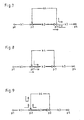
- the road network for mathematical processing is represented by a route search algorithm as a graph with edges k and node p, the edges representing corresponding roads and the nodes corresponding mesh points of the roads.
- edges k 1 , k 2 , k 3 and k 4 and four nodes p 1 , p 2 , p 3 and p 4 are provided. Since the traffic flow is directed in real traffic, an edge k must also be represented as a directed vector.
- the edges k are also resistances, Sogn. Distance resistances, assigned, which represents a measure of an effort to drive from one node in the network to another. For example, the edge length is used as a line resistance.
- a travel time on an edge may be considered as their respective road resistance.
- a cost function is provided, which allows a weighted mixed costing of various properties, such as edge length, travel time on an edge or width (expansion state) of an edge.
- the respective nodes are optionally assigned a resistor that reflects costs of driving maneuvers (straight off, left / right, turn, turn, etc.).
- all best-path algorithms determine a route between a start edge and a target edge in the directed graph with the property that the sum of all path resistances of the edges of the determined route and possibly the considered node resistances is minimal.
- Such best-path algorithms work backward iteratively for route calculation and visit all edges in the graph and evaluate them for the best way to the destination edge.
- a resistance-favorable path to edges listed in the list is searched backwards, which in the previous iteration step were optimized.
- the method returns from each edge in the graph an optimal route to the target edge.
- Route table created. Such a table would exemplify the in Fig. 1 The graphs shown below look like this.
- the table shows the resistance up to the target edge and the trailing edge following in the target direction.
- the resistance is set to "infinity" (symbol ⁇ ) and the trailing edge to "undefined” (symbol -).
- a positive sign in the resistance and successor column stands for the consideration of the respective edge in its direction of the arrow, whereas a negative sign stands for the consideration of the respective edge opposite to the direction of the arrow.
- the target edge in the route table is initialized to zero resistance (see above).
- the edge k 3 should serve here.
- the result for a destination initialization is the following appearance for the stored route table. route table edge + Wderstand + Successor edge -Resistance -Nach plausiblekante k 1 ⁇ - ⁇ - k 2 ⁇ - ⁇ - k 3 0 - 0 - k 4 ⁇ - ⁇ -
- the target edge k 3 is entered in a list of the already optimized edges stored in the navigation device, so that a list of the already optimized edges according to the following list 1 results.
- a second list is provided for storing the edges to be checked in the next optimization step, which is empty at the beginning of the method, according to list 1 below.
- List 2 list of edges to be checked in the next step
- resistance denotes the resistance entered in the route table and "line resistance” in the graph (cf. Fig. 1 ) of the respective edge associated track resistance. If this resistance optimization condition is met, the resistance of the incoming edge in the route table is replaced by the new, smaller value, and the actual edge as the trailing edge entered and the optimized Ankommer edge added to the list 2. If all edges from list 1 have been processed as described, list 1 and list 2 are swapped, and then list 2 is emptied. The procedure terminates when list 1 is found empty.
- step 1 the following contents result for list 2 and the route table: List 2 (list of edges to be checked in the next step) + k 2 -k 4 edge + resistance + Successor edge -Resistance -Nach discountedkante k 1 ⁇ - ⁇ - k 2 10 + k 3 ⁇ - k 3 0 - 0 - k 4 ⁇ - 30 + k 3
- Step 2 starts with a new list 1 with the following content: List 1 (list of already optimized edges) + k 2 -k 4
- step 2.1 all incoming edges of the edge + k 2 are checked for the resistance optimization condition as well as in Fig. 3 illustrated, and there are the following contents of the route table and list 2: List 2 (list of edges to be checked in the next step) + k 1 + k 4 -k 2 edge + resistance + Successor edge -Resistance -Nach discountedkante k 1 20 + k 2 ⁇ - k 2 10 + k 3 20 + k 2 k 3 0 - 0 - k 4 40 + k 2 30 + k 3
- a subsequent step 2.2 all incoming edge edges -k 4 are checked for the resistance optimization condition, as well as in FIG Fig. 4 illustrated, and there are the following contents of the route table and list 2: List 2 (list of edges to be checked in the next step) + k 1 + k 4 -k 2 edge + resistance + Successor edge -Resistance -Nach discountedkante k 1 20 + k 2 ⁇ - k 2 10 + k 3 20 + k 2 k 3 0 - 0 - k 4 40 + k 2 30 + k 3
- the next step 3 starts with a list 1 with the following content: List 1 (list of already optimized edges) + k 1 + k 4 -k 2
- the edge + k 1 receives the trailing edge + k 2 , the edge + k 2 the trailing edge + k 3, and the edge + k 3 no trailing edge, ie target reached.
- This determined route is in Fig. 5 illustrated with a dashed arrow.
- each edge additionally at least one traffic route type route value is assigned, in the determination of the route from one edge to the next edge primarily the traffic route type route value is minimized and only in the event that this traffic route way value of an edge to the next neither increased nor decreased at this point, a minimization of Strekkenwiderstandes is performed.
- the traffic route type route value indicates the sum of all routes on which this edge has a predetermined traffic route type, such as a highway, a country road, a ferry, a pass road, and / or a tunnel and / or the like.
- a predetermined traffic route type such as a highway, a country road, a ferry, a pass road, and / or a tunnel and / or the like.
- the sum of all traffic route type route values of the calculated route directly indicates the length of the unwanted route sections remaining in the calculated route. If this is displayed to the user, for example, after the route calculation, the latter can check for himself to what extent the criteria he has specified for sections to be avoided or his route options be respected.
- a further advantageous embodiment of the traffic route type route value is the recording of frequencies, such as, for example, the number of traffic accidents, the number of speed traps or traffic lights that are possibly associated with an edge.
- the traffic route type route value also serves to record other physical properties, such as pollutant emissions, which are assigned to an edge in order to avoid areas that are prone to smog during route selection.
- the properties assigned to an edge for detection in the traffic route type route value are optionally imported directly by means of traffic telematics, for example, by a service provider online, for example via GSM, into a navigation device.
- a polygon is transmitted that marks an area on the digital map within which all edges are assigned a predetermined property.
- the consideration of at least one traffic route type route value in the route calculation is selectively activated or deactivated by a user.
- the route calculation is carried out, for example, iteratively starting from the destination edge.
- each edge is additionally a r outing o ptions-relevant S trek PROPORTION, hereinafter referred to briefly as "ROSA value” or "Verpourswegeart path value,” assigned.
- ROSA value indicates, for example, in meters the length of predetermined traffic routes on this edge, such as highway, main road, country road, state highway, municipal road, tunnel, underpass, pass road, dangerous route, winding road, accident prone route, route with construction site, route with predetermined speed limit , Bridge, jam-prone route and / or town crossing or the like.
- This ROSA value is managed for each edge in and against its arrow direction (+ ROSA, -ROSA).
- the traffic route types are available to a user, for example, as route options that can be freely selected or activated / deactivated.
- the ROSA value of a calculated route thus indicates the sum of all lengths to be avoided up to the destination edge. For example, if the route options "shallow ferries" and “shallow freeway" are enabled and an edge has a ROSA value of 1000m, then this means that 1000m of that edge must be traveled on ferry and / or highway routes to the desired destination reach.
- An essential core of the invention is that the method calculates a route having a minimum ROSA value compared to all other alternative routes.
- the method according to the invention additionally manages two columns for the ROSA values of respective edges in and against the arrow direction in the route table.
- “resistance” or “traffic route type value” or “ROSA value” designates a value entered in the route table
- “ distance resistance” or “traffic route type value” or “value” ROSA route nwert” denotes a value assigned to an edge in the map of the route network as edges and nodes.
- the ROSA values of all edges are set to infinity (symbol ⁇ ).
- the target edge receives the pink and zero resistance values.
- the target edge is again + k 3 , which is entered as the starting point of the iterative route calculation in a first list for already optimized edges.
- List 1 list of already optimized edges + k 3
- an additional optimization check of the ROSA value of the respectively examined incoming edges is carried out before the optimization test of the resistor with the following optimization condition: PINK - value ⁇ Ankommer - edge > PINK - distance value ⁇ Ankommer - edge + PINK - value ⁇ is - edge
- the ROSA route value of an incoming edge is determined from the sum of all route sections or traffic route types which are predetermined on this edge as to be avoided. It should be pointed out explicitly that in the present case the terms "PINK VALUE” or “PINK route value” and “traffic route type value” or “traffic route type route value” are to be regarded as synonymous.
- the incoming edge is optimized regardless of whether its resistance to the target increases or not.
- the ROSA value of the incoming edge in the route table is replaced by the new, lower value
- the resistance of the incoming edge is updated in the route table, as the trailing edge
- the actual edge is entered in the route table and the optimized ankommer Edge is added to the second list.
- a check is made of the resistance optimization condition when PINK - value ⁇ Ankommer - edge PINK - distance value ⁇ Ankommer - edge + PINK - value ⁇ is - edge or the incoming edge is discarded as not optimizable, and it continues with the next incoming edge to be checked if PINK - value ⁇ Ankommer - edge ⁇ PINK - distance value ⁇ Ankommer - edge + PINK - value ⁇ is - edge
- Step 1 is based on the following first list: List 1 (list of already optimized edges) + k 3
- step 1 List 2 (list of edges to be checked in the next step) + k 2 -k 4 edge + resistance + ROSA + Successor edge -Resistance -PINK -Nachdecierkante k 1 ⁇ ⁇ - ⁇ ⁇ - k 2 10 10 + k 3 ⁇ ⁇ - k 3 0 0 - 0 - k 4 ⁇ ⁇ - 30 0 + k 3
- Step 2 starts with a list 1 with the following content: List 1 (list of already optimized edges) + k 2 -k 4
- the effect of the ROSA optimization check becomes particularly clear: the incoming edge + k 1 resulted in the example of Fig. 1 to 5 over the successor + k 2 to the goal. Since, however, when guiding over + k 4 to the target, the ROSA value drops from 10 to 0, the edge -k 4 is noted as a successor in the route table due to the fulfilled ROSA optimization condition. With in other words, the highway is avoided as desired, although the resistance to the destination increases from 20 to 40.
- the ROSA optimization condition is also satisfied for the remaining incoming edges -k 2 and + k 4 .
- step 3 The method is then continued in an analogous manner with step 3, 4, etc., until at the beginning of an iteration step the first list is empty.
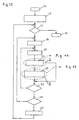
- FIGS. 10 to 12 illustrate in respective flow charts the inventive method.
- the method starts with step 10 and in step 12, an initialization takes place, wherein the target edge is included in a first list and a second list is emptied. Further, the route table is initialized. In the following step 14 it is checked whether the first list is empty. If this is the case, the method ends in step 16. Otherwise, in step 18, the next edge is retrieved from the first list and determined as an actual edge.
- step 20 an unexamined arrival edge of the actual edge determined in step 18 is selected, and in step 22, a ROSA optimization is performed, which is detailed Fig. 11 is apparent.
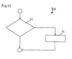
- the ROSA optimization condition becomes PINK - value ⁇ Ankommer - edge > PINK - distance value ⁇ Ankommer - edge + PINK - value ⁇ is - edge checked. If this is satisfied, the currently checked incoming edge is entered in the second list in step 26, and the ROSA value and the resistance value of this incoming edge are updated in the route table and finally, the actual edge is entered as the successor edge of the incoming edge. Thereafter, the method continues with the step 36 explained below.
- step 36 If the result is negative, the method continues in step 36, otherwise in step 34 the incoming edge is entered in the second list, the ROSA value and the resistance value in the route table are updated and the actual edge is entered as the successor. Thereafter, the method proceeds to step 36, in which it is checked whether all the incoming edges belonging to the current actual edge have already been processed. If this is not the case, the method branches to step 20, otherwise step 38 continues, in which it is checked whether all edges from the first list have been checked. If not, the process branches to step 18, otherwise in step 40 the first and second lists are swapped and the new second list cleared and returned to step 14.
- a separate detection takes place in separate counters or ROSA values. For example, if you enter your own ROSA values for motorway, toll and ferry length components of the route, Thus, the order of the then necessary three consecutive ROSA optimization checks determines the priority of the categories to be avoided. In this case, the prioritization, ie the sequence of the ROSA optimization checks, is predefined or predeterminable by the user.
Landscapes
- Engineering & Computer Science (AREA)
- Radar, Positioning & Navigation (AREA)
- Remote Sensing (AREA)
- Automation & Control Theory (AREA)
- Physics & Mathematics (AREA)
- General Physics & Mathematics (AREA)
- Navigation (AREA)
Claims (9)
- Procédé pour déterminer un trajet à partir d'un point de départ vers un point de destination dans un réseau de voies de circulation notamment un réseau routier enregistré dans une mémoire sous la forme de segments dirigés (k1-K4) et de noeuds (p1-p4),
une résistance de trajet étant associée à chaque segment,
le trajet se détermine sous la forme d'une série de segments de façon que la somme de toutes les résistances de trajet soit minimale,
caractérisé en ce qu'
à chaque segment, on associe en plus au moins une valeur de segment de type de trajet,
et pour la détermination du trajet, pour passer d'un segment au segment suivant, on minimise principalement la valeur de trajet de type de voie de circulation, et
uniquement au cas où cette valeur de trajet de type de voie de circulation d'un segment au segment suivant n'augmente ni diminue, on effectue à cet endroit une minimisation de la résistance de trajet. - Procédé selon la revendication 1,
caractérisé en ce que
la valeur de trajet de tous les types de voie de circulation indique la somme de tous les trajets pour laquelle ce segment correspond à un type de voie de circulation prédéfini, comme par exemple une autoroute, une route nationale, un bac, une route de col et/ou un tunnel et/ou une voie de circulation analogue. - Procédé selon la revendication 1 ou 2,
caractérisé en ce que
la valeur de trajet de type de voie de circulation correspond à la fréquence par exemple d'accidents de circulation, d'emplacements de radar et/ou de feux rouges associés à un segment. - Procédé selon les revendications précédentes,
caractérisé en ce que
la valeur de trajet de type de voie de circulation contient les propriétés physiques d'un segment telles que par exemple les émissions de matières polluante correspondant à un segment. - Procédé selon les revendications précédentes,
caractérisé en ce que
les propriétés associées à un segment pour sa prise en compte dans la valeur de trajet de type de segment de voie de circulation sont fournies directement par un système de télématique de circulation, par exemple par un fournisseur de services en ligne tel que par exemple le système GSM à un appareil de navigation. - Procédé selon la revendication 5,
caractérisé en ce qu'
on transmet un polygone qui marque une zone sur la carte numérique à l'intérieur de laquelle tous les segments ont une propriété prédéfinie. - Procédé selon les revendications précédentes,
caractérisé en ce que
la prise en compte d'au moins une valeur de trajet de type de voie de circulation est sélectivement activée ou désactivée par l'utilisateur lors du calcul du trajet. - Procédé selon les revendications précédentes,
caractérisé en ce que
le calcul du trajet se fait de manière itérative en partant du segment de destination. - Procédé selon la revendication 8,
caractérisé par
les étapes suivantes:(A) Etablissement d'un tableau de trajet dans lequel on enregistre une résistance respective pour chaque segment orienté dans la direction de marche avant et la direction de marche arrière, chaque fois un segment suivant et chaque fois une valeur de type de voie de circulation,(B) On donne à toutes les valeurs de résistance ainsi qu'à toutes les valeurs de type de voie de circulation du tableau de trajet, la valeur infinie et on efface tous les segments suivants,(C) On donne la valeur zéro aux valeurs de résistance et aux valeurs de type de voie de circulation du segment de destination,(D) On enregistre le segment de destination dans une première liste pour des segments déjà optimisés,(E) On établit une seconde liste vide pour les segments à optimiser dans l'étape suivante,(F) On détermine si la première liste est vide et si la réponse est affirmative, on termine le procédé,(G) On définit un segment de la première liste comme segment réel,(H) On définit tous les segments maillés avec le segment réel comme étant des segments d'entrée,(I) On détermine pour tous les segments d'entrée si une condition d'optimisation est remplie: valeur du type de voie de circulation (segment d'entrée) supérieure à la valeur de segment de type de voie de circulation (segment d'entrée) plus valeur de type de voie de circulation (segment réel) et si cette condition est remplie (réponse affirmative), on passe à l'étape (K); si la réponse est négative, on passe à l'étape (L),(K) Enregistrement du segment d'entrée respectif dans la seconde liste, mise de la valeur de résistance du segment d'entrée respectif dans le tableau de trajet sur la somme [résistance de segment (segment d'entrée) + résistance (segment réel)], mise à l'état de la valeur du type de voie de circulation pour le segment d'entrée respectif dans le tableau de trajet sur la somme [valeur de trajet de type à voie de circulation (segment d'entrée) + valeur de voie de circulation (segment réel)] et enregistrement du segment réel comme segment suivant du segment d'entrée respectif, et passage à l'étape (M),(L) Rejet du segment d'entrée respectif si
 - Si la réponse est positive, enregistrement du segment d'entrée respectif dans la seconde liste, mise de la valeur de résistance du segment d'entrée respectif dans le tableau de trajet sur la somme (valeur de la résistance de trajet (à l'intérieur segment d'entrée) + résistance (segment réel)), inscription de la valeur de type de voie de circulation du segment d'entrée respectif dans le tableau de trajet sur la somme (valeur de trajet de type de voie de circulation (segment d'entrée) + valeur de type de voie de circulation (valeur réelle)), et enregistrement du segment réel comme segment suivant du segment d'entrée respectif,- Si la réponse est négative, rejet du segment d'entrée,(M) Enregistrement d'un autre segment de la première liste comme segment réel et passage à l'étape (H) ou
Passage à l'étape (N) si déjà tous les segments contenus dans la première liste ont été enregistrés comme segments réels,(N) Echange de la première liste avec la seconde liste, mise à la corbeille de la seconde liste et passage à l'étape (F).
Applications Claiming Priority (2)
| Application Number | Priority Date | Filing Date | Title |
|---|---|---|---|
| DE19836485A DE19836485A1 (de) | 1998-08-12 | 1998-08-12 | Verfahren zum Bestimmen einer Route von einem Ausgangspunkt zu einem Zielpunkt auf einem Routennetz |
| DE19836485 | 1998-08-12 |
Publications (3)
| Publication Number | Publication Date |
|---|---|
| EP0979987A2 EP0979987A2 (fr) | 2000-02-16 |
| EP0979987A3 EP0979987A3 (fr) | 2002-08-28 |
| EP0979987B1 true EP0979987B1 (fr) | 2008-09-10 |
Family
ID=7877272
Family Applications (1)
| Application Number | Title | Priority Date | Filing Date |
|---|---|---|---|
| EP99111285A Expired - Lifetime EP0979987B1 (fr) | 1998-08-12 | 1999-06-10 | Méthode pour déterminer une route d'un point de départ à un point d'arrivée |
Country Status (3)
| Country | Link |
|---|---|
| US (1) | US6230099B1 (fr) |
| EP (1) | EP0979987B1 (fr) |
| DE (2) | DE19836485A1 (fr) |
Families Citing this family (35)
| Publication number | Priority date | Publication date | Assignee | Title |
|---|---|---|---|---|
| DE19829538A1 (de) * | 1998-07-02 | 2000-01-05 | Bosch Gmbh Robert | Verfahren zur Beeinflussung von Quelldaten zur Bestimmung einer Route bei einem Navigationssystem |
| US20040215387A1 (en) | 2002-02-14 | 2004-10-28 | Matsushita Electric Industrial Co., Ltd. | Method for transmitting location information on a digital map, apparatus for implementing the method, and traffic information provision/reception system |
| JP3481168B2 (ja) | 1999-08-27 | 2003-12-22 | 松下電器産業株式会社 | デジタル地図の位置情報伝達方法 |
| US6480785B1 (en) * | 2000-09-06 | 2002-11-12 | Vindigo, Inc. | System for determining a route and presenting navigational instructions therefor |
| DE10043797A1 (de) * | 2000-09-06 | 2002-03-28 | Daimler Chrysler Ag | Integriertes Verkehrsüberwachungssystem |
| JP5041638B2 (ja) | 2000-12-08 | 2012-10-03 | パナソニック株式会社 | デジタル地図の位置情報伝達方法とそれに使用する装置 |
| DE10061044C2 (de) | 2000-12-08 | 2002-10-31 | Bosch Gmbh Robert | Verfahren zum automatischen Löschen einer Verkehrsmeldung |
| US20020077746A1 (en) * | 2000-12-14 | 2002-06-20 | Gary Zuber | Method and apparatus for providing routes using auto ferries and channels |
| JP4663136B2 (ja) | 2001-01-29 | 2011-03-30 | パナソニック株式会社 | デジタル地図の位置情報伝達方法と装置 |
| JP4749594B2 (ja) * | 2001-04-27 | 2011-08-17 | パナソニック株式会社 | デジタル地図の位置情報伝達方法 |
| JP4230132B2 (ja) | 2001-05-01 | 2009-02-25 | パナソニック株式会社 | デジタル地図の形状ベクトルの符号化方法と位置情報伝達方法とそれを実施する装置 |
| DE10128517A1 (de) * | 2001-06-13 | 2003-01-02 | Vodafone Ag | Verfahren zum Erzeugen von Navigationsdaten für eine Routenführung sowie Navigationssystem |
| DE10131841A1 (de) * | 2001-06-30 | 2003-01-16 | Wissenschaftliche Werkstatt Fu | Verfahren zur umweltgerechten Staffelung von Straßennutzungsgebühren für Nutzfahrzeuge |
| DE10139549A1 (de) * | 2001-08-10 | 2003-03-06 | Bosch Gmbh Robert | Verfahren zum Ermitteln von Routen und darauf bezogenes Navigationssystem |
| US6609063B1 (en) * | 2001-10-12 | 2003-08-19 | Navigation Technologies Corp. | System and method for using a map database with attributed no-outlet and circular segments |
| US8392457B1 (en) | 2001-10-12 | 2013-03-05 | Navteq B.V. | System and method for forming a map database with no-outlet and circular segments |
| WO2003062749A2 (fr) * | 2002-01-23 | 2003-07-31 | M-Spatial Limited | Generation schematique |
| DE10203097A1 (de) * | 2002-01-25 | 2003-08-14 | Ages Arbeitsgemeinschaft Gebue | Verfahren zum Bestimmen einer Fahrtstrecke in einem Streckennetz und zum Bestimmen von für die Streckenbenutzung zu entrichtenden Gebühren |
| US8560223B2 (en) | 2002-08-29 | 2013-10-15 | Mapquest, Inc. | Automated route determination |
| ATE347089T1 (de) * | 2004-05-27 | 2006-12-15 | Delphi Tech Inc | Kraftfahrzeugnavigationsgerät |
| WO2007020053A1 (fr) * | 2005-08-19 | 2007-02-22 | Daimler Ag | Procede d'evaluation pour identifier des routes empruntees |
| GB0520576D0 (en) * | 2005-10-10 | 2005-11-16 | Applied Generics Ltd | Using traffic monitoring information to provide better driver route planning |
| US7761350B1 (en) * | 2006-04-26 | 2010-07-20 | Aol Inc. | Biasing of search result clustering to ensure more effective point of interest (POI) targeting |
| US7774734B2 (en) * | 2006-11-06 | 2010-08-10 | Microsoft Corporation | Enhanced reach-based graph processing using shortcuts |
| DE102007017240A1 (de) * | 2007-04-12 | 2008-10-16 | Robert Bosch Gmbh | Verfahren und Zielführungseinrichtung zur Ermittlung einer Fahrtroute |
| DE102007019244A1 (de) * | 2007-04-24 | 2008-10-30 | Robert Bosch Gmbh | Navigationseinrichtung und Verfahren zur grafischen Darstellung von Teilgebieten mit Verkehrsbeschränkungen |
| DE102007042412A1 (de) | 2007-09-06 | 2009-03-12 | Robert Bosch Gmbh | Verfahren zur Reiseplanung, Verfahren zur Routenberechnung und Navigationssystem |
| DE102007050021A1 (de) * | 2007-10-17 | 2009-04-23 | Navigon Ag | Verfahren zum Betrieb eines Navigationssystems |
| CN102187178B (zh) * | 2008-12-22 | 2015-11-25 | 电子地图北美公司 | 用于绿色路线选择的方法、装置和地图数据库 |
| US8412445B2 (en) * | 2011-02-18 | 2013-04-02 | Honda Motor Co., Ltd | Predictive routing system and method |
| CN103049656B (zh) * | 2012-12-19 | 2017-04-12 | 中国铁道科学研究院 | 欧拉图的构造方法及基于该方法进行测试序列优化的方法 |
| US9478074B2 (en) * | 2014-01-21 | 2016-10-25 | Speedgauge, Inc. | Vehicle management |
| US20150228096A1 (en) * | 2014-02-12 | 2015-08-13 | International Business Machines Corporation | Directed graph visualization |
| US9201426B1 (en) * | 2014-02-19 | 2015-12-01 | Google Inc. | Reverse iteration of planning data for system control |
| CN108515862A (zh) * | 2018-03-26 | 2018-09-11 | 唐天才 | 一种用于电动汽车的数据智能管理系统 |
Family Cites Families (4)
| Publication number | Priority date | Publication date | Assignee | Title |
|---|---|---|---|---|
| DE3719017A1 (de) * | 1987-06-06 | 1988-12-15 | Bosch Gmbh Robert | Verfahren und vorrichtung zur bestimmung einer fahrtroute zwischen einem startpunkt und einem zielpunkt |
| US5938720A (en) | 1995-02-09 | 1999-08-17 | Visteon Technologies, Llc | Route generation in a vehicle navigation system |
| JP3173983B2 (ja) * | 1995-12-28 | 2001-06-04 | 松下電器産業株式会社 | 経路選出方法およびシステム |
| KR100279761B1 (ko) * | 1996-12-09 | 2001-02-01 | 하기와라 가즈토시 | 경로 탐색 장치 |
-
1998
- 1998-08-12 DE DE19836485A patent/DE19836485A1/de not_active Withdrawn
-
1999
- 1999-06-10 EP EP99111285A patent/EP0979987B1/fr not_active Expired - Lifetime
- 1999-06-10 DE DE59914866T patent/DE59914866D1/de not_active Expired - Lifetime
- 1999-07-15 US US09/354,559 patent/US6230099B1/en not_active Expired - Lifetime
Also Published As
| Publication number | Publication date |
|---|---|
| DE59914866D1 (de) | 2008-10-23 |
| DE19836485A1 (de) | 2000-02-17 |
| EP0979987A3 (fr) | 2002-08-28 |
| EP0979987A2 (fr) | 2000-02-16 |
| US6230099B1 (en) | 2001-05-08 |
Similar Documents
| Publication | Publication Date | Title |
|---|---|---|
| EP0979987B1 (fr) | Méthode pour déterminer une route d'un point de départ à un point d'arrivée | |
| EP1105696B1 (fr) | Procede et dispositif pour determiner une route entre un point de depart et un point d'arrivee | |
| DE69925779T2 (de) | Routensuchvorrichtung | |
| DE69218140T2 (de) | Fahrtleitvorrichtung für Fahrzeug | |
| EP1092127B2 (fr) | Procede pour influencer des donnees source afin de determiner un itineraire dans un systeme de navigation | |
| DE10012502B4 (de) | Fahrzeugnavigationssystem, das Kartendaten über Strassen eingeschränkter Art verwendet | |
| WO2001006479A1 (fr) | Procede de navigation pour un moyen de transport | |
| DE10146744A1 (de) | Verfahren und System zum Bereitstellen von Fahrspurempfehlungen | |
| DE102014008151A1 (de) | Verfahren zum Betrieb eines Kraftfahrzeugs | |
| EP1102227B1 (fr) | Procédé pour le guidage dynamique d'un véhicule | |
| EP1957940B1 (fr) | Procede de navigation pour au moins un moyen de deplacement | |
| DE102007058093B4 (de) | Verfahren und Vorrichtung zum Ermitteln einer Routenempfehlung aus einer Mehrzahl von Wegstrecken | |
| DE102021100250A1 (de) | Durch crowdsourcing erhaltene navigationssysteme und -verfahren | |
| EP1423661B1 (fr) | Procede pour determiner des itineraires et systeme de navigation associe | |
| WO2009071366A1 (fr) | Procédé de fonctionnement d'un système d'information et système d'information | |
| DE102008029430B4 (de) | Verfahren zum Betrieb eines Navigationssystems | |
| EP1342221B1 (fr) | Procede permettant d'effacer automatiquement une signalisation de trafic | |
| EP0889454A2 (fr) | Procédé et centrale de pronostic et d'analyse d'un réseau de circulation | |
| DE102006027832A1 (de) | Fahrzeugnavigationssystem | |
| DE102020115950B4 (de) | Verfahren und Vorrichtung zur Ermittlung einer funktionalen Straßenklasse und einer wahrscheinlichsten Wegstrecke für ein Kraftfahrzeug | |
| DE102021005438A1 (de) | Verfahren zur Bestimmung von Streckenattributen in einer Straßenkarte eines Fahrzeugsystems aus Schilderbeobachtungen | |
| EP2205942B1 (fr) | Système de navigation et procédé de détermination d'itinéraire | |
| DE102016010028B4 (de) | Technik zum lokalen Auswählen einer Route in einem Verkehrsnetz durch ein Fahrzeugnavigationsgerät | |
| EP2028445A2 (fr) | Procédé et dispositif de détermination d'un itinéraire dans un réseau routier | |
| DE19739538A1 (de) | Navigationsvorrichtung |
Legal Events
| Date | Code | Title | Description |
|---|---|---|---|
| PUAI | Public reference made under article 153(3) epc to a published international application that has entered the european phase |
Free format text: ORIGINAL CODE: 0009012 |
|
| AK | Designated contracting states |
Kind code of ref document: A2 Designated state(s): AT BE CH CY DE DK ES FI FR GB GR IE IT LI LU MC NL PT SE |
|
| AX | Request for extension of the european patent |
Free format text: AL;LT;LV;MK;RO;SI |
|
| RTI1 | Title (correction) |
Free format text: METHOD FOR DETERMINING A ROUTE FROM AN ORIGINAL POINT TO A TARGET POINT |
|
| PUAL | Search report despatched |
Free format text: ORIGINAL CODE: 0009013 |
|
| AK | Designated contracting states |
Kind code of ref document: A3 Designated state(s): AT BE CH CY DE DK ES FI FR GB GR IE IT LI LU MC NL PT SE |
|
| AX | Request for extension of the european patent |
Free format text: AL;LT;LV;MK;RO;SI |
|
| RIC1 | Information provided on ipc code assigned before grant |
Free format text: 7G 01C 21/00 A, 7G 01C 21/20 B, 7G 01C 21/26 B |
|
| 17P | Request for examination filed |
Effective date: 20030228 |
|
| AKX | Designation fees paid |
Designated state(s): DE FR GB IT |
|
| RIC1 | Information provided on ipc code assigned before grant |
Ipc: G01C 21/34 20060101AFI20080418BHEP |
|
| RTI1 | Title (correction) |
Free format text: METHOD OF DETERMINING A ROUTE FROM A POINT OF ORIGIN TO A DESTINATION |
|
| GRAP | Despatch of communication of intention to grant a patent |
Free format text: ORIGINAL CODE: EPIDOSNIGR1 |
|
| GRAS | Grant fee paid |
Free format text: ORIGINAL CODE: EPIDOSNIGR3 |
|
| GRAA | (expected) grant |
Free format text: ORIGINAL CODE: 0009210 |
|
| AK | Designated contracting states |
Kind code of ref document: B1 Designated state(s): DE FR GB IT |
|
| REG | Reference to a national code |
Ref country code: GB Ref legal event code: FG4D Free format text: NOT ENGLISH |
|
| REF | Corresponds to: |
Ref document number: 59914866 Country of ref document: DE Date of ref document: 20081023 Kind code of ref document: P |
|
| PLBE | No opposition filed within time limit |
Free format text: ORIGINAL CODE: 0009261 |
|
| STAA | Information on the status of an ep patent application or granted ep patent |
Free format text: STATUS: NO OPPOSITION FILED WITHIN TIME LIMIT |
|
| 26N | No opposition filed |
Effective date: 20090611 |
|
| REG | Reference to a national code |
Ref country code: FR Ref legal event code: PLFP Year of fee payment: 18 |
|
| REG | Reference to a national code |
Ref country code: FR Ref legal event code: PLFP Year of fee payment: 19 |
|
| REG | Reference to a national code |
Ref country code: FR Ref legal event code: PLFP Year of fee payment: 20 |
|
| PGFP | Annual fee paid to national office [announced via postgrant information from national office to epo] |
Ref country code: FR Payment date: 20180625 Year of fee payment: 20 |
|
| PGFP | Annual fee paid to national office [announced via postgrant information from national office to epo] |
Ref country code: DE Payment date: 20180807 Year of fee payment: 20 Ref country code: GB Payment date: 20180626 Year of fee payment: 20 Ref country code: IT Payment date: 20180622 Year of fee payment: 20 |
|
| REG | Reference to a national code |
Ref country code: DE Ref legal event code: R071 Ref document number: 59914866 Country of ref document: DE |
|
| REG | Reference to a national code |
Ref country code: GB Ref legal event code: PE20 Expiry date: 20190609 |
|
| PG25 | Lapsed in a contracting state [announced via postgrant information from national office to epo] |
Ref country code: GB Free format text: LAPSE BECAUSE OF EXPIRATION OF PROTECTION Effective date: 20190609 |