EP0980121A2 - Adaptateur pour lampe fluorescente compacte - Google Patents
Adaptateur pour lampe fluorescente compacte Download PDFInfo
- Publication number
- EP0980121A2 EP0980121A2 EP99305683A EP99305683A EP0980121A2 EP 0980121 A2 EP0980121 A2 EP 0980121A2 EP 99305683 A EP99305683 A EP 99305683A EP 99305683 A EP99305683 A EP 99305683A EP 0980121 A2 EP0980121 A2 EP 0980121A2
- Authority
- EP
- European Patent Office
- Prior art keywords
- fluorescent lamp
- adapter
- socket
- terminal pins
- base
- Prior art date
- Legal status (The legal status is an assumption and is not a legal conclusion. Google has not performed a legal analysis and makes no representation as to the accuracy of the status listed.)
- Withdrawn
Links
- 239000007858 starting material Substances 0.000 claims abstract description 23
- 230000005611 electricity Effects 0.000 claims description 28
- 239000004020 conductor Substances 0.000 claims description 7
- 230000007246 mechanism Effects 0.000 claims description 6
- 230000001276 controlling effect Effects 0.000 claims 1
- 230000001105 regulatory effect Effects 0.000 claims 1
- 230000008901 benefit Effects 0.000 description 3
- 239000003245 coal Substances 0.000 description 1
- 238000010276 construction Methods 0.000 description 1
- 230000009977 dual effect Effects 0.000 description 1
- 239000000446 fuel Substances 0.000 description 1
- 230000003116 impacting effect Effects 0.000 description 1
- 239000012858 resilient material Substances 0.000 description 1
- 102200094740 rs1085307938 Human genes 0.000 description 1
- 239000007787 solid Substances 0.000 description 1
- 239000012815 thermoplastic material Substances 0.000 description 1
Images




Classifications
-
- F—MECHANICAL ENGINEERING; LIGHTING; HEATING; WEAPONS; BLASTING
- F21—LIGHTING
- F21V—FUNCTIONAL FEATURES OR DETAILS OF LIGHTING DEVICES OR SYSTEMS THEREOF; STRUCTURAL COMBINATIONS OF LIGHTING DEVICES WITH OTHER ARTICLES, NOT OTHERWISE PROVIDED FOR
- F21V19/00—Fastening of light sources or lamp holders
- F21V19/0075—Fastening of light sources or lamp holders of tubular light sources, e.g. ring-shaped fluorescent light sources
- F21V19/0095—Fastening of light sources or lamp holders of tubular light sources, e.g. ring-shaped fluorescent light sources of U-shaped tubular light sources, e.g. compact fluorescent tubes
-
- H—ELECTRICITY
- H01—ELECTRIC ELEMENTS
- H01R—ELECTRICALLY-CONDUCTIVE CONNECTIONS; STRUCTURAL ASSOCIATIONS OF A PLURALITY OF MUTUALLY-INSULATED ELECTRICAL CONNECTING ELEMENTS; COUPLING DEVICES; CURRENT COLLECTORS
- H01R33/00—Coupling devices specially adapted for supporting apparatus and having one part acting as a holder providing support and electrical connection via a counterpart which is structurally associated with the apparatus, e.g. lamp holders; Separate parts thereof
- H01R33/94—Holders formed as intermediate parts for linking a counter-part to a coupling part
- H01R33/942—Holders formed as intermediate parts for linking a counter-part to a coupling part for tubular fluorescent lamps
-
- Y—GENERAL TAGGING OF NEW TECHNOLOGICAL DEVELOPMENTS; GENERAL TAGGING OF CROSS-SECTIONAL TECHNOLOGIES SPANNING OVER SEVERAL SECTIONS OF THE IPC; TECHNICAL SUBJECTS COVERED BY FORMER USPC CROSS-REFERENCE ART COLLECTIONS [XRACs] AND DIGESTS
- Y02—TECHNOLOGIES OR APPLICATIONS FOR MITIGATION OR ADAPTATION AGAINST CLIMATE CHANGE
- Y02B—CLIMATE CHANGE MITIGATION TECHNOLOGIES RELATED TO BUILDINGS, e.g. HOUSING, HOUSE APPLIANCES OR RELATED END-USER APPLICATIONS
- Y02B20/00—Energy efficient lighting technologies, e.g. halogen lamps or gas discharge lamps
Definitions
- the present invention relates to an assembly for use with compact fluorescent lamps.
- the invention relates to a universal adapter and socket assembly for using different types of compact fluorescent lamps offered in the market
- Incandescent lamps are gaining popularity as replacements for incandescent lamps.
- Incandescent lamps are presently used in a variety of applications.
- Incandescent lamps are used as table lamps, desk lamps, ceiling lamps, and the like.
- Incandescent lamps have been popular due to their effectiveness in providing light.
- incandescent lamps are frequently used on a continuous basis, sometimes being left on overnight or over the course of a number of days. The continuous use of incandescent lamps creates a problem.
- the pollution is generated by the power companies that rely upon natural resources such as coal, as fuel to produce electricity. Due to the continuous use of incandescent lamps, more and more electricity must be generated. As a result, as power companies increase output to meet the demands for more electricity, the amount of the natural resources that are consumed and the amount of pollution generated by such power companies also increases.
- compact fluorescent lamps have been designed as energy saving replacements for incandescent lamps.
- compact fluorescent lamps typically have a higher rated life than most incandescent lamps.
- a compact fluorescent lamp usually has a rated life between 10,000 and 20,000 hours in comparison to 750 to 1000 hours for incandescent lamps.
- compact fluorescent lamps use only a fraction of the power normally needed to run an incandescent lamp of relatively the same intensity. By using only a fraction of the power, the costs associated with running a compact fluorescent lamp, in comparison to an incandescent lamp, is greatly reduced.
- the initial cost associated with converting from an incandescent lamp to a compact fluorescent lamp is more expensive than replacing a light bulb, the cost is more than compensated over the life of the compact fluorescent lamp. Accordingly, compact fluorescent lamps have proven to be an attractive cost effective and energy conscious replacement for incandescent lamps.
- a typical compact fluorescent lamp includes a fluorescent tube that is connected to a base from which one or more terminal pins extend.
- the fluorescent tubes are manufactured having a variety of configurations. For instance, some fluorescent tubes have a dual U-shaped configuration while others have a circular or circline configuration.
- the base is designed to support the fluorescent tubes and provide a means of electrical connection. Manufacturers have separated the variety of pin configurations into the following classifications: two pin configurations (commercially known as G23, GX23, and G24D bases), four-pin configurations (commercially known as GX32D and 2G11 bases), and quad pin configurations.
- a post or housing also extends from the base, positioned intermediate the terminal pins.
- the housing sometimes referred to as a “starter housing”, is used to store the starter elements of the compact fluorescent lamp that are connected to the terminal pins.
- the starter housing also adds to the stability to the fluorescent lamp.
- the present invention provides an apparatus and socket assembly for use with a variety of compact fluorescent lamps offered in the market. It is an object of this invention to provide a socket for use with compact fluorescent lamps. It is also an object of this invention to provide an adapter that will permit the consumer to use a variety of compact fluorescent lamps with a single socket.
- the present invention relates to an assembly for use with a compact fluorescent lamp.
- the assembly includes a socket and an adapter.
- the socket has an annular wall having a top surface and at least one edge defining its periphery.
- An opening extends downward from the top surface of the wall to define a cavity or recess for receiving a portion of the compact fluorescent lamp.
- a plurality of spaced part holes are provided on the top surface, each hole being positioned to receive one of the terminal pins of the compact fluorescent lamp.
- the spaced apart holes are connected to a switching assembly that is disposed within the socket to control the flow of electricity to the compact fluorescent lamp.
- the adapter is designed to connect the socket to the compact fluorescent lamp.
- the adapter includes a base having a top surface and a bottom surface. An opening extends downward from the top surface to form a recess to receive a portion of the fluorescent lamp. The opening is surrounded by a plurality of spaced part holes that are provided on the top surface. Each hole is positioned to receive one of the terminal pins of the compact fluorescent lamp.
- a plurality of terminal pins extend downwardly from the bottom surface of the adapter. Each terminal pin is positioned to be telescopically received in one of the spaced apart holes of the socket.
- the base may include a secondary adapter that is designed to electrically connect with the terminal pins of the compact fluorescent lamp.
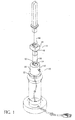
- Figure 1 is a perspective exploded view of an adapter and a socket for using a compact fluorescent lamp as contemplated by the present invention.
- FIG 2 is a perspective view of the socket of the present invention shown in Figure 1.
- FIG 3 is a top plan view of the socket of the present invention shown in Figure 2.
- Figure 4 is a sectional view of the socket of the present invention shown in Figure 3, taken along line 4-4.
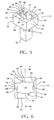
- Figure 5 is a perspective view of an adapter of the present invention shown in Figure 1.
- Figure 6 is a top plan view of the adapter of the present invention shown in Figure 5.
- Figure 7 is a sectional view of the adapter of the present invention shown in figure 6, taken along line 7-7.
- Figure 8 is a perspective exploded view of another embodiment of the present invention.
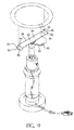
- Figure 9 is a perspective exploded view of another embodiment of the present invention.
- the assembly generally includes a socket which is designated by the number 10 and an adapter 12.
- the socket 10 is designed to engage a typical compact fluorescent lamp.
- the compact fluorescent lamp will have a fluorescent tube that is attached to a base.
- the base includes a plurality of terminal pins that extend downwardly away from the fluorescent tube.
- a post or starter housing also extends from the base to store the starter elements of the fluorescent lamp.
- a pair of molded detents are attached to opposite sides of the starter housing to secure the fluorescent lamp within the socket 10.
- the socket 10 includes a top surface 14 and a housing 16.
- the housing 16 is annular having an outer surface 18 and an inner surface 20.
- the outer surface 18 generally defines the outer periphery of the housing 16 and extends downwardly from the top surface 14 toward the bottom end 22 of the socket 10.
- the inner surface 20 is positioned radially inward from the outer surface 18 and also extends downward from the top surface 14. The distance between the outer surface 18 and the inner surface 20 generally defines the thickness of the top surface 14.
- the inner surface 20 is defined by a plurality of sides 24 that are joined to each other at the corners to form a recess 26 or cavity.
- the recess 26 extends below the top surface 14 and terminates in a floor 28 that is positioned above the bottom end 22 of the socket 10. (See Figure 4).
- the recess 26 should be deep enough to substantially receive the starter housing of the fluorescent lamp that extends from the base.
- the recess 26 includes a pair of opposed grooves 30 that are provided to help align the fluorescent lamp when it is inserted into the socket 10.
- Each groove 30 extends downwardly from the top surface 12 to the floor 28 of the recess 26.
- the grooves 30 are formed to receive an oppositely formed member that projects from the side of the starter housing of the fluorescent lamp.
- the groove 30 is optional and can be eliminated without impacting upon the performance of the socket 10.
- the recess 26 may have any configuration.
- the recess 26 may be advantageously cylindrical to accommodate a substantially cylindrically shaped post or housing. It should be understood by those of ordinary skill in the art that the cross-section of the recess 26 will be slightly larger than the cross-section of the starter housing so that the fluorescent lamp may be easily, but firmly inserted into and removed from the socket 10 without causing damage.
- a series of hooks 32 are formed on the inner surface 20 of the recess 26 to engage the detents of the fluorescent lamp. As shown in Figures 2 and 3, the hooks 32 are positioned on opposite sides 24 of the recess 26 to engage each of the detents of the fluorescent lamp. Each hook 32 projects outward from its attached side 24 and includes a ramp 34 that tapers upwardly to a vertex. When the fluorescent lamp is inserted into the socket 10, the detents of the fluorescent lamp will slide along each ramp 34 until the fluorescent lamp snaps in place.
- the hooks 32 and detents form a locking mechanism or means to ensure that the fluorescent lamp remains securely seated within the recess 26 of the socket 10. It is contemplated that other forms of locking mechanisms may be used consistent with the spirit and purpose of the present invention.
- the switch assembly 36 for the socket 10.
- the switch assembly 36 is provided within the housing 14 as a means to control the flow of electricity to and within the socket 10.
- the switch assembly 36 includes a switching means that is operatively attached to a knob 38 that projects outward from a hole in the outer surface 16 of the housing 14.
- the knob 38 may be rotated clockwise to its "on” or “off” position relative to the electricity that may flow to the socket 10.
- the switching means can be replaced by other switches such as a push button switch, a pivot switch, a dimmer or the like. Switches of this sort may be operated manually or by electronically controlled devices.
- the switching means and switch assembly 36 are available in today's market from a number of manufacturers having commonly recognized configurations.
- a series of holes 40 are provided on the top surface 12 of the socket 10.
- the holes 40 are spaced part from each other to coincide with the relative spacing between and among the terminal pins of the fluorescent lamp.
- the holes 40 are positioned around the recess 26, intermediate the outer surface 18 and the inner surface 20 of the socket 10.
- each hole 40 extends below the top surface 12 toward the bottom end 22 of the socket 10 and is wide enough to receive each of the terminal pins of the fluorescent lamp.
- a suitable form of conductive material or other electricity conducting means to firmly grasp each of the terminal pins.
- the hole 40 and conductive means combine to form a channel 42 for electrically engaging the terminal pins. Once the terminal pins are nested within the channel 42, electricity can flow from the socket 10, through the conductive material and into the fluorescent lamp.
- the socket 10 may be connected to a typical lamp holder that may be used as a table or desk lamp.
- the socket 10 may be formed using suitable thermoplastic material known in the art.
- the socket 10 may generally include a line cord that extends from its bottom end 18 and connects to a plug having a pair of male prongs. The prongs are adapted to be inserted to a typical female AC electrical outlet.
- the lamp holder, line cord, and plug are available in the market from a number of manufacturers and do not form any significant part of the present invention. Accordingly, no further discussion of these parts is necessary.
- the adapter 12 is provided for use with the socket 10.
- the adapter 12 includes a substantially rectangular base 44 having a top surface 46 and a bottom surface 48.
- the base 44 is bordered by at least one edge 50 that defines its outer periphery.
- the base 44 includes a housing 52 having a plurality of walls 54. Each wall 54 is connected at the corners and extends downward from the top surface 46 toward the bottom surface 48 of the adapter 12.
- Wall 54 includes an outer surface 56 and an inner surface 58.
- the distance between the outer surface 56 and the inner surface 58 further defines the relative thickness of the housing 52.
- the inner surface 58 has a plurality of sides 60 that are joined to each other at the corners to form a recess or cavity 62.
- the recess 62 serves the same purposes as the recess 62 of the socket 10. Accordingly, the recess 62 should be large enough to substantially but firmly receive the starter housing of the fluorescent lamp.
- a pair of opposed grooves 64 that help align the compact fluorescent lamp when it is inserted.
- Each groove 64 extends downwardly from the top surface 46 to the floor of the recess 62.
- the grooves are formed to receive an oppositely formed member that projects from the side of the starter housing of the compact fluorescent lamp.
- the grooves 64 are optional and can be eliminated.
- a pair of hooks 66 are provided within the recess 62 of the adapter 12. As shown in Figure 5, the hooks 66 are positioned to engage the detents of the flourescent lamp. Each hook 66 includes a ramp 68 that tapers outwardly from the inner surface 58 to its vertex. When the flourescent lamp is inserted, the detents will slide upwardly along each ramp 68 until the flourescent lamp snaps in place.
- the hooks 66 and detents of the fluorescent lamp serve as a locking mechanism or a means to ensure that the fluorescent lamp remains securely positioned within the adapter 12. Other locking mechanisms or means may be used within the scope of the present invention.
- a post 70 extends downward from the bottom surface 48 of the base 44 toward the recess 26 of the socket 10. As shown in Figure 5, the post 70 is substantially rectangular having four sides that are joined to one another at the corners. The post 70 is positioned inward of the outer edge 50 of the base 44 so that the adapter 12 will have a generally T-shaped configuration. The post 70 may be used to store the electrical components of the adapter 12 and provide stability within the socket 10 once the adapter 12 is inserted.
- the post 70 may have a variety of shapes and sizes, depending upon the configuration of the recess 26 of the socket 10 or the electrical components it may be used to store.
- the post 70 may have a cylindrical configuration that matches a substantially cylindrically shaped recess 26.
- the post 70 may also be used as a means to draw the electricity from the socket 10 by having some form of conductive material provided therein. It is contemplated, that the post may be used in a similar fashion to a terminal pin to draw electricity to the flourescent lamp.
- detents 72 are positioned on opposite sides 74 of the block 70, similar to the detents that are formed on the compact fluorescent lamp. Each detent 72 is positioned to slidably engage in locking fashion the hooks 32 formed within recess 26. The detents 72 are part of the locking mechanism that is used to maintain he adapter 12 is firmly secured within the socket 10.
- the holes 74 are positioned on the top surface 46 of the adapter 12 to receive at least one of the terminal pins of the fluorescent lamp.
- a suitable form of conductive material or other conducting means to firmly grasp each of the terminal pins of the fluorescent lamp.
- the combination of the hole 74 and the conductive material forms a channel 76 that projects downward to the bottom end 48 of the base 44. Once the terminal pins are nested within the channel 76, electricity can flow into the fluorescent lamp to illuminate the fluorescent bulbs.
- the electricity means includes a series of terminal pins 78 that are electrically connected to a plurality of spaced apart holes 74.
- the terminal pins 78 extend downward from the bottom surface 48 of the base 44 toward the socket 10.
- the terminal pins 78 are spaced away from one another to coincide with the relative position and spacing between and among the holes 40 provided the socket 10.
- the adapter 12 includes a substantially solid base 44 having a top surface 46 and at least one edge defining its outer perimeter.
- the electricity conducting means of the adapter 12 includes a line cord 80 or wire that is connected to a secondary or auxiliary adapter 82.
- the line cord 80 has one or more wires that are electrically connected to each of the terminal pins of the adapter 12 to permit electricity to flow to the fluorescent lamp.
- the secondary adapter 82 includes a plurality of holes 84 or channels to receive at least one of the terminal pins of the fluorescent lamp.
- FIG. 9 shows a further embodiment of the present invention.
- the adapter 12 includes a support member 86 attached to the top surface 46 of the base 44.
- the support member 86 is designed to support a substantially circular fluorescent lamp and includes a pair of arms 88 extending outwardly from one another relative to the central vertical axis of the adapter 12.
- Each arm 88 includes a U-shaped flange 90 that defines a recess 92 to firmly grasp the fluorescent tube.
- the inner edges 94 of the flange and outer edges 96 of the flange 92 are slightly curved having a radius that is substantially the same as that of the circular fluorescent lamp.
- the arms 88 and flange 90 are made of resilient material to bend flexibly and to apply enough reactive force to support the fluorescent lamp.
- the electricity conductive means of the adapter 12 shown in this embodiment also includes the line card 80 and the secondary adapter 82.
- the secondary adapter 82 includes the plurality of holes 82 that are designed to electrically connect to the terminal pins of the circular fluorescent tube.
- the socket 10 is designed to receive a typical compact fluorescent lamp having four basic parts: a fluorescent tube, a base, terminal pins, and a post.
- the fluorescent tube is connected at one end to the base from which the terminal pins and the post extend.
- the fluorescent tube may have a U-shaped configuration (as illustrated in Figure 1) or may have other configurations as illustrated in Figures 8 and 9, respectively.
- Various size fluorescent tubes are manufactured and sold by today's fluorescent lamp manufacturers each of which include different size bases and terminal pin configurations.
- the combination of the socket 10 and the adapter 12 allows the consumer to use a variety of compact fluorescent lamps.
- the socket 10 may be embodied in other configurations other than an annular configuration as illustrated in Figures 1, 8 and 9.
- the holes 40 that are provided on the top surface 12 may vary in number depending largely upon the number of terminal pins that extend from the base of the compact fluorescent lamp.
- the socket 10 may include a single hole 40 for bases having a slimline or single pin configuration. It is contemplated that other sockets and pin configurations may be used with the present invention.
- the apparatus shown in Figures 1, 8 and 9 is easily assembled.
- the apparatus is assembled by inserting the adapter 12 into the socket 10 followed by the fluorescent lamp.
- the terminal pins of the adapter 12 will slide into each of the holes 40 of the socket 10.
- the adapter 12 will be telescopically received by the recess 26 of the socket 10.
- the adapters 12 should be pushed in far enough so that the bottom surface of each base 44 will rest on top of the top surface 12 of the socket 10.
- the present invention fills the need for providing a universal apparatus that permits different compact fluorescent lamps to be used with one lamp assembly.
- Each of the adapters 12 described above may be used with the same socket.
- Use of the adapters eliminates the need for a separate socket for each of the different types of base configurations for compact fluorescent lamps presently offered in the market.
- the adapter 12 and the socket 10 provide the consumer with flexibility in choosing a particular type of compact fluorescent lamp.
Landscapes
- Engineering & Computer Science (AREA)
- General Engineering & Computer Science (AREA)
- Fastening Of Light Sources Or Lamp Holders (AREA)
Applications Claiming Priority (2)
| Application Number | Priority Date | Filing Date | Title |
|---|---|---|---|
| US132653 | 1998-08-12 | ||
| US09/132,653 US6059593A (en) | 1998-08-12 | 1998-08-12 | Adapter and socket assembly for a compact fluorescent lamp |
Publications (2)
| Publication Number | Publication Date |
|---|---|
| EP0980121A2 true EP0980121A2 (fr) | 2000-02-16 |
| EP0980121A3 EP0980121A3 (fr) | 2001-06-27 |
Family
ID=22454992
Family Applications (1)
| Application Number | Title | Priority Date | Filing Date |
|---|---|---|---|
| EP99305683A Withdrawn EP0980121A3 (fr) | 1998-08-12 | 1999-07-16 | Adaptateur pour lampe fluorescente compacte |
Country Status (4)
| Country | Link |
|---|---|
| US (2) | US6059593A (fr) |
| EP (1) | EP0980121A3 (fr) |
| BR (1) | BR9903647A (fr) |
| CA (1) | CA2279760C (fr) |
Cited By (4)
| Publication number | Priority date | Publication date | Assignee | Title |
|---|---|---|---|---|
| WO2008099311A1 (fr) * | 2007-02-12 | 2008-08-21 | Koninklijke Philips Electronics N.V. | Lampe, douille de lampe et ensemble d'une telle lampe et d'une telle douille de lampe |
| DE102009006549B3 (de) * | 2009-01-29 | 2010-12-09 | Osram Gesellschaft mit beschränkter Haftung | Adapter für mindestens eine Kompaktleuchtstofflampe |
| DE102009026399A1 (de) * | 2009-08-19 | 2011-02-24 | Aml Licht + Design Gmbh | Leuchtmittelfassungsadapter |
| EP1989762A4 (fr) * | 2006-02-27 | 2011-05-18 | Light Sources Inc | Lampe ultraviolette a utiliser dans un epurateur d'eau |
Families Citing this family (20)
| Publication number | Priority date | Publication date | Assignee | Title |
|---|---|---|---|---|
| US6146170A (en) * | 1998-07-07 | 2000-11-14 | Fumin; Guan | Adaptor for using a plug-in type compact fluorescent lamp in an R7s lampholder |
| AU6466701A (en) * | 2000-05-16 | 2001-11-26 | Air Fiber Inc | Optical transceiver design and mechanical features |
| US6582253B1 (en) * | 2000-06-01 | 2003-06-24 | Kenneth Lau | Lock-in compact fluorescent lamp (CFL) adaptor |
| US6241543B1 (en) * | 2000-08-29 | 2001-06-05 | Chao-Lin Mai | Tubular lamp assembly |
| US6837726B1 (en) * | 2001-08-23 | 2005-01-04 | E.G.L. Company, Inc. | Holder for discharge lamp |
| US6666700B2 (en) * | 2001-08-23 | 2003-12-23 | E.G.L. Company, Inc. | Holder for discharge lamp |
| US6561831B1 (en) * | 2001-12-27 | 2003-05-13 | Hon Hai Precision Ind. Co., Ltd. | Housing of socket connector and conductive terminal thereof |
| US6746260B2 (en) | 2002-07-31 | 2004-06-08 | Maytag Corporation | Universal lamp holder assembly for an appliance |
| US6802730B2 (en) * | 2002-08-13 | 2004-10-12 | Rhine Electronic Co., Ltd. | Separation device of an electronic stabilizer body and a fixing seat |
| WO2005045878A2 (fr) * | 2003-11-07 | 2005-05-19 | Philips Intellectual Property & Standards Gmbh | Boitier demarreur pour lampe a decharge gazeuse, et son procede de montage |
| US7125159B2 (en) * | 2004-04-20 | 2006-10-24 | Sea Gull Lighting Products, Inc. | Non-defeatable fluorescent adapter for incandescent fixture |
| WO2006041410A2 (fr) | 2004-10-12 | 2006-04-20 | Grenzone Pte Ltd | Ampoule electrique robuste |
| CN1805106A (zh) * | 2005-01-11 | 2006-07-19 | 海鸥照明产品有限公司 | 荧光灯 |
| US7569981B1 (en) * | 2005-02-22 | 2009-08-04 | Light Sources, Inc. | Ultraviolet germicidal lamp base and socket |
| DE102006021055A1 (de) * | 2006-05-05 | 2007-11-08 | Patent-Treuhand-Gesellschaft für elektrische Glühlampen mbH | Adapter für eine Einbaulampe |
| US7661977B2 (en) * | 2006-09-25 | 2010-02-16 | Light Sources, Inc. | Snap-lock connector |
| WO2008039448A2 (fr) * | 2006-09-25 | 2008-04-03 | Lightsources Inc. | Connecteur à verrouillage à ressort |
| US20080192508A1 (en) * | 2007-02-08 | 2008-08-14 | Skip Busby Consulting Llc | Method of Lighting a Cabinet or Display Case and Lighting Assembly Therefore |
| WO2009142722A2 (fr) * | 2008-05-20 | 2009-11-26 | Hirsh Donald G | Luminaires fluorescents compacts, et ensembles de conversion et adaptateurs pour lampes associés |
| DE102011001410A1 (de) * | 2011-03-18 | 2012-09-20 | Occhio GmbH | Adapter für eine Leuchtmittelfassung |
Citations (1)
| Publication number | Priority date | Publication date | Assignee | Title |
|---|---|---|---|---|
| US4713019A (en) | 1986-09-17 | 1987-12-15 | Edwin Gaynor | Sockets for compact fluorescent lamps |
Family Cites Families (17)
| Publication number | Priority date | Publication date | Assignee | Title |
|---|---|---|---|---|
| CA466808A (fr) * | 1950-07-25 | Canadian General Electric Company | Interrupteur de demarrage | |
| JPS5686473A (en) * | 1979-12-18 | 1981-07-14 | Mitsubishi Electric Corp | Socket for fluorescent lamp with starter |
| US4570105A (en) * | 1983-09-20 | 1986-02-11 | Engel Herman J | Electrical adapter for use in connection with fluorescent lamps |
| US4495443A (en) * | 1984-01-27 | 1985-01-22 | Cummings John H | Compact fluorescent lamp combination, and method of making it |
| US4596433A (en) * | 1984-12-13 | 1986-06-24 | North American Philips Corporation | Lampholder having internal cooling passages |
| US4739454A (en) * | 1986-06-17 | 1988-04-19 | Starbrite Lighting Ltd. | Adjustable display light |
| US4936789A (en) * | 1989-08-01 | 1990-06-26 | Joseph Ugalde | Method and apparatus for preventing the theft of a fluorescent lamp and ballast transformer |
| USD321857S (en) | 1989-12-01 | 1991-11-26 | Gte Products Corporation | Fluorescent lamp holder or the like |
| US5362246A (en) * | 1993-05-12 | 1994-11-08 | Kenneth Lau | Convertible fluorescent adaptor with compacted installation mode |
| DE9206294U1 (de) * | 1992-05-11 | 1992-07-02 | Patent-Treuhand-Gesellschaft für elektrische Glühlampen mbH, 8000 München | Adapter für eine einseitig gesockelte Niederdruckentladungslampe |
| GB2271891B (en) * | 1992-10-21 | 1997-02-12 | John Richard Archer | Improvements in and relating to lighting |
| US5390096A (en) * | 1992-10-22 | 1995-02-14 | Progressive Technology In Lighting, Inc. | Replacement compact fluorescent lamp assembly |
| KR0129581Y1 (ko) * | 1993-11-05 | 1998-12-15 | 조성호 | 컴팩트 형광등의 안정기 구조 |
| US5634820A (en) * | 1994-03-11 | 1997-06-03 | Lights Of America, Inc. | Fluorescent light adaptor module |
| USD362733S (en) | 1994-04-05 | 1995-09-26 | Moriyama Sangyo K.K. | Decorative lamp |
| US5759054A (en) * | 1995-10-06 | 1998-06-02 | Pacific Scientific Company | Locking, wire-in fluorescent light adapter |
| US5707246A (en) * | 1996-01-16 | 1998-01-13 | Progressive Technology In Lighting, Inc. | Security device for lamp adaptor |
-
1998
- 1998-08-12 US US09/132,653 patent/US6059593A/en not_active Expired - Fee Related
-
1999
- 1999-07-16 EP EP99305683A patent/EP0980121A3/fr not_active Withdrawn
- 1999-07-30 CA CA002279760A patent/CA2279760C/fr not_active Expired - Fee Related
- 1999-08-11 BR BR9903647-9A patent/BR9903647A/pt not_active Application Discontinuation
-
2000
- 2000-02-01 US US09/495,776 patent/US6190191B1/en not_active Expired - Fee Related
Patent Citations (1)
| Publication number | Priority date | Publication date | Assignee | Title |
|---|---|---|---|---|
| US4713019A (en) | 1986-09-17 | 1987-12-15 | Edwin Gaynor | Sockets for compact fluorescent lamps |
Cited By (4)
| Publication number | Priority date | Publication date | Assignee | Title |
|---|---|---|---|---|
| EP1989762A4 (fr) * | 2006-02-27 | 2011-05-18 | Light Sources Inc | Lampe ultraviolette a utiliser dans un epurateur d'eau |
| WO2008099311A1 (fr) * | 2007-02-12 | 2008-08-21 | Koninklijke Philips Electronics N.V. | Lampe, douille de lampe et ensemble d'une telle lampe et d'une telle douille de lampe |
| DE102009006549B3 (de) * | 2009-01-29 | 2010-12-09 | Osram Gesellschaft mit beschränkter Haftung | Adapter für mindestens eine Kompaktleuchtstofflampe |
| DE102009026399A1 (de) * | 2009-08-19 | 2011-02-24 | Aml Licht + Design Gmbh | Leuchtmittelfassungsadapter |
Also Published As
| Publication number | Publication date |
|---|---|
| CA2279760C (fr) | 2002-09-17 |
| EP0980121A3 (fr) | 2001-06-27 |
| BR9903647A (pt) | 2000-08-29 |
| CA2279760A1 (fr) | 2000-02-12 |
| US6190191B1 (en) | 2001-02-20 |
| US6059593A (en) | 2000-05-09 |
Similar Documents
| Publication | Publication Date | Title |
|---|---|---|
| CA2279760C (fr) | Ensemble adaptateur et douille pour lampe fluorescente compacte | |
| US6722774B2 (en) | Double lamp utility light | |
| US7391182B2 (en) | Autoilluminating rechargeable lamp system | |
| US6819080B2 (en) | Autoilluminating lamp system | |
| EP1297724B1 (fr) | Systeme de lampes rechargeables | |
| US5759054A (en) | Locking, wire-in fluorescent light adapter | |
| US7527392B2 (en) | Rechargeable fluorescent utility light | |
| US5546291A (en) | Conversion kit assembly for a light bulb | |
| AU2001268676A1 (en) | Rechargeable lamp system | |
| US6531824B1 (en) | Universal electronic plug-in replaceable fluorescent lamp ballast and adapter | |
| US6162100A (en) | Adapter for Edison/Bayonet light sockets | |
| US4316120A (en) | Circular fluorescent lamp unit | |
| US4278911A (en) | Circular fluorescent lamp unit | |
| EP0198423A2 (fr) | Douille de lampe à base tournante | |
| US7090381B2 (en) | Fluorescent utility light | |
| US4654557A (en) | Lamp holder assembly having rotatable base | |
| US6905225B2 (en) | Floodlight and spotlight adapter and enclosure | |
| MXPA99007445A (en) | Adapter assembly and receptacle for a fluorescent lamp compa | |
| US4850900A (en) | Light fixture lampholder | |
| CN218033051U (zh) | 一种自动平衡灯串亮度的led灯具 | |
| EP1126212B1 (fr) | Luminaire de sécurité | |
| KR200399889Y1 (ko) | 등기구의 마구리 구조 | |
| CN2146063Y (zh) | 插脚灯座 | |
| CA1152048A (fr) | Lampe fluorescente circulaire | |
| CN2114227U (zh) | 插接式灯头 |
Legal Events
| Date | Code | Title | Description |
|---|---|---|---|
| PUAI | Public reference made under article 153(3) epc to a published international application that has entered the european phase |
Free format text: ORIGINAL CODE: 0009012 |
|
| 17P | Request for examination filed |
Effective date: 19990724 |
|
| AK | Designated contracting states |
Kind code of ref document: A2 Designated state(s): AT BE CH CY DE DK ES FI FR GB GR IE IT LI LU MC NL PT SE |
|
| AX | Request for extension of the european patent |
Free format text: AL;LT;LV;MK;RO;SI |
|
| PUAL | Search report despatched |
Free format text: ORIGINAL CODE: 0009013 |
|
| AK | Designated contracting states |
Kind code of ref document: A3 Designated state(s): AT BE CH CY DE DK ES FI FR GB GR IE IT LI LU MC NL PT SE |
|
| AX | Request for extension of the european patent |
Free format text: AL;LT;LV;MK;RO;SI |
|
| AKX | Designation fees paid |
Free format text: AT BE CH CY DE DK ES FI FR GB GR IE IT LI LU MC NL PT SE |
|
| 17Q | First examination report despatched |
Effective date: 20020827 |
|
| STAA | Information on the status of an ep patent application or granted ep patent |
Free format text: STATUS: THE APPLICATION IS DEEMED TO BE WITHDRAWN |
|
| 18D | Application deemed to be withdrawn |
Effective date: 20030108 |