EP0980132B1 - Wechselstromgenerator für Kraftfahrzeuge - Google Patents
Wechselstromgenerator für Kraftfahrzeuge Download PDFInfo
- Publication number
- EP0980132B1 EP0980132B1 EP99115149A EP99115149A EP0980132B1 EP 0980132 B1 EP0980132 B1 EP 0980132B1 EP 99115149 A EP99115149 A EP 99115149A EP 99115149 A EP99115149 A EP 99115149A EP 0980132 B1 EP0980132 B1 EP 0980132B1
- Authority
- EP
- European Patent Office
- Prior art keywords
- stator
- rotor
- housing
- generator
- winding
- Prior art date
- Legal status (The legal status is an assumption and is not a legal conclusion. Google has not performed a legal analysis and makes no representation as to the accuracy of the status listed.)
- Expired - Lifetime
Links
- 238000004804 winding Methods 0.000 claims description 51
- 210000000078 claw Anatomy 0.000 claims description 20
- 239000000498 cooling water Substances 0.000 claims description 11
- 239000007788 liquid Substances 0.000 claims description 4
- 239000002470 thermal conductor Substances 0.000 claims description 4
- 230000002265 prevention Effects 0.000 claims description 3
- 239000003507 refrigerant Substances 0.000 claims description 2
- 238000001816 cooling Methods 0.000 description 21
- 229920005989 resin Polymers 0.000 description 20
- 239000011347 resin Substances 0.000 description 20
- 239000002826 coolant Substances 0.000 description 9
- 238000010276 construction Methods 0.000 description 7
- XLYOFNOQVPJJNP-UHFFFAOYSA-N water Substances O XLYOFNOQVPJJNP-UHFFFAOYSA-N 0.000 description 7
- 230000005855 radiation Effects 0.000 description 5
- RYGMFSIKBFXOCR-UHFFFAOYSA-N Copper Chemical compound [Cu] RYGMFSIKBFXOCR-UHFFFAOYSA-N 0.000 description 4
- 229910052802 copper Inorganic materials 0.000 description 4
- 239000010949 copper Substances 0.000 description 4
- 230000000694 effects Effects 0.000 description 4
- 238000010248 power generation Methods 0.000 description 4
- 230000007423 decrease Effects 0.000 description 3
- 230000004907 flux Effects 0.000 description 3
- 239000000463 material Substances 0.000 description 3
- 238000000034 method Methods 0.000 description 3
- 230000002093 peripheral effect Effects 0.000 description 3
- 230000010355 oscillation Effects 0.000 description 2
- 229920002379 silicone rubber Polymers 0.000 description 2
- 230000006835 compression Effects 0.000 description 1
- 238000007906 compression Methods 0.000 description 1
- 230000003247 decreasing effect Effects 0.000 description 1
- 230000001419 dependent effect Effects 0.000 description 1
- 238000010586 diagram Methods 0.000 description 1
- 230000005611 electricity Effects 0.000 description 1
- 239000003822 epoxy resin Substances 0.000 description 1
- 230000020169 heat generation Effects 0.000 description 1
- 238000002347 injection Methods 0.000 description 1
- 239000007924 injection Substances 0.000 description 1
- 230000009191 jumping Effects 0.000 description 1
- 230000005389 magnetism Effects 0.000 description 1
- 238000004519 manufacturing process Methods 0.000 description 1
- 229910052751 metal Inorganic materials 0.000 description 1
- 239000002184 metal Substances 0.000 description 1
- 229910001172 neodymium magnet Inorganic materials 0.000 description 1
- 239000004033 plastic Substances 0.000 description 1
- 229920000647 polyepoxide Polymers 0.000 description 1
Images

Classifications
-
- H—ELECTRICITY
- H02—GENERATION; CONVERSION OR DISTRIBUTION OF ELECTRIC POWER
- H02K—DYNAMO-ELECTRIC MACHINES
- H02K1/00—Details of the magnetic circuit
- H02K1/06—Details of the magnetic circuit characterised by the shape, form or construction
- H02K1/22—Rotating parts of the magnetic circuit
- H02K1/24—Rotor cores with salient poles ; Variable reluctance rotors
- H02K1/243—Rotor cores with salient poles ; Variable reluctance rotors of the claw-pole type
-
- H—ELECTRICITY
- H02—GENERATION; CONVERSION OR DISTRIBUTION OF ELECTRIC POWER
- H02K—DYNAMO-ELECTRIC MACHINES
- H02K9/00—Arrangements for cooling or ventilating
- H02K9/22—Arrangements for cooling or ventilating by solid heat conducting material embedded in, or arranged in contact with, the stator or rotor, e.g. heat bridges
- H02K9/227—Heat sinks
-
- H—ELECTRICITY
- H02—GENERATION; CONVERSION OR DISTRIBUTION OF ELECTRIC POWER
- H02K—DYNAMO-ELECTRIC MACHINES
- H02K5/00—Casings; Enclosures; Supports
- H02K5/04—Casings or enclosures characterised by the shape, form or construction thereof
- H02K5/20—Casings or enclosures characterised by the shape, form or construction thereof with channels or ducts for flow of cooling medium
-
- H—ELECTRICITY
- H02—GENERATION; CONVERSION OR DISTRIBUTION OF ELECTRIC POWER
- H02K—DYNAMO-ELECTRIC MACHINES
- H02K5/00—Casings; Enclosures; Supports
- H02K5/04—Casings or enclosures characterised by the shape, form or construction thereof
- H02K5/20—Casings or enclosures characterised by the shape, form or construction thereof with channels or ducts for flow of cooling medium
- H02K5/203—Casings or enclosures characterised by the shape, form or construction thereof with channels or ducts for flow of cooling medium specially adapted for liquids, e.g. cooling jackets
Definitions
- a device provided a resin material in a slot of a stator winding in order to reduce magnetism sound is disclosed in Japanese Patent Laid-open No. 7-255140 bulletin.
- the electromagnetic sound in the slot part may be reduced, but it is not considered on an electromagnetic sound which occurs at an end coil.
- US 5 329 199 discloses a rotor assembly with molded fans.
- mold material is injection molded at high pressure into open spaces between pole pieces and a mold.
- US 5 313 698 discloses a process for the manufacture of the stator of an electrical machine.
- two preassembled stator plate stacks are kept axially distant from each other and are molded together by a heat conducting plastic.
- This stator constructional unit is then removed from the compression mold and inserted into a heated pot shaped metal housing, which in turn - during use - is cooled from outside.
- the first object of the present invention is to reduce the electromagnetic sound in the AC generator.
- the second object of the present invention is to realize cooling enhancement of the field winding and the stator winding.
- a liquid cooling system using a liquid refrigerant is adopted as a cooling means in the present invention, claw shape magnetic poles and a field winding of the rotor are molded with a good thermal conduction resin, thereby rigidity of the rotor is raised simultaneously.
- a slot part of the stator core and whole end coil are hardened by said good thermal conduction resin, thereby total rigidity of the stator is raised in the same way as the rotor and generation of the electromagnetic sound is reduced. Moreover heat from a heat generation origin is thermally conducted through said good thermal conduction resin, thereby the cooling enhancement is planned for.
- a gap between the bracket and the rotor is constructed to be narrowed in the present invention.
- FIG. 1 to FIG. 3 The first embodiment of the present invention will be explained referring to FIG. 1 to FIG. 3 as follows.
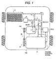
- Fig. 1 is a total block-diagram which shows a relationship between the AC generator and an engine installed in an engine room of a vehicle 100.
- an AC generator 1 is connected to a pulley 102 arranged on a shaft end of the AC generator 1 for an engine 2 and a pulley 31 arranged on a shaft end of the engine 2 through belt 32.
- a pulley ratio of this pulley 102 and the pulley 31 is from 2 to 3 times, and the AC generator turns at a higher speed than the engine.
- cooling water of the AC generator 1 is flown in to two radiator hoses 4 connected with a radiator 5 for its heat exchanging, and a cooling-water pump 6 to circulate the cooling water is arranged at an outlet port side of the radiator 5.
- This cooling-water pump 6, although this is not shown in the figures, is normally connected to the pulley 31 of the engine 2, and the cooling-water pump 6 may transmit a quantity of the water to the AC generator 1 in proportion to a revolutional speed of the engine 2.
- the water flown from the radiator 5 through the cooling-water pump 6 is also used for cooling of the engine 2.
- the radiator hose 4 is connected to the outlet port side of the AC generator 1, and as a cooling stem is constructed to form a parallel connection. Therefore, balance of water quantity flown in the parallel connected cooling stem is decided by a pressure loss in a pipe arrangement of each cooling stem.
- coolant temperature sensors are installed in respective radiator hoses so as to detect the temperature of the coolant, and the detected temperature signals are inputted to an ECU as a control unit for the engine 2 so as to be used to control the generated electric current of the AC generator 1 for the vehicle 100.
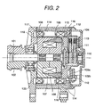
- FIG. 2 a longitudinal sectional view showing a total construction of the AC generator for the vehicle is shown.
- the AC generator 1 has two brackets, a bracket 103 arranged at a pulley side and a rear bracket 104 arranged at a counter pulley side.
- a shaft 101 is supported through a bearing in a central part of both of the brackets, and a pulley 102 is installed on one end of the shaft 101 and a collector ring 110 is installed on another end thereof.
- the pulley 102 is connected to the pulley 31 arranged on the output shaft of the engine through the belt 32 shown in FIG. 1, and turns in proportion to a revolutional speed of the engine 2.
- a brush 111 is mounted on the collector ring 110, and electric power is supplied from the brush 111 into a field winding 107 which will be explained later.
- a rotor is installed, and a pair of claw shape magnetic poles 108 having a configuration of a claw shape is arranged in a periphery part of the rotor.
- the field winding 107 is wound in a central part of the rotor, and the claw shape magnetic poles 108 are magnetized by flowing a direct current from the collector ring 110 into the field winding 107.
- a good thermal conduction resin 116 is arranged in a part between the claw shape magnetic pole 108 and the field winding 107, and a scattering prevention cover 117 to prevent jumping out of the good thermal conduction resin 116 is arranged in the most peripheral part of the claw shape magnetic pole 108 of the rotor.
- a housing 115 enclosing a stator core 105 is arranged between the pulley side drive side bearing bracket 103 and the counter-pulley side rear bracket 104, and the internal circumference of the stator core 105 is arranged to be separated keeping a very small interval from the scattering prevention cover 117 arranged on the claw shape magnetic pole 108 of the rotor. This interval is decided beforehand based on a relationship of necessary mechanical characteristic, and is around 0.4 mm generally.
- a plurality of teeth and slots are arranged in the stator core 105, the stator windings 106 of three phase are bound in the slots being a concave part of this stator core 105, and the three phase voltage is induced in the stator winding 106, when the claw shape magnetic pole 108 turns and is magnetized by being driven with the engine.
- the stator core 105 is fixed inside the housing 115 by a shrinkage fit method and the good thermal conduction resin 116 is filled up in a clearance around the end coil part of the stator winding 106 and in the slot of the stator core 105, so that the stator core 105, the stator winding 106 and the housing 115 are formed with the good thermal conduction resin 116 as one body as the result, so as to be connected thermally.
- the good thermal conduction resin described here is, for example, material of a silicon rubber system having a thermal conductivity greater than 1.5 W/mK or epoxy resin having a high thermal conductivity.
- a plus fin 109a of diodes which is a module of the diodes constituting a rectifier circuit and a minus fin 109b of the diodes are fixed to a rear plate 112, which tightly seals a cooling water channel 114.
- an integrated circuit regulator 113 to adjust the power generation voltage is fixed so as to be in contact with the rear bracket 104 mentioned above.
- the plus fin 109a of the diodes is connected to a plus electrode of the battery which is not illustrated, and the minus fin 109b of the diodes, having an electric potential the same as that of the AC generator body, is connected electrically to the minus terminal side of the battery which is not illustrated.
- These diodes full-wave rectify the alternating current voltage that is induced in the stator winding 106 to convert it into DC voltage.
- the integrated circuit regulator 113 controls the field winding current so that the DC voltage that is rectified by the diodes in order to charge the battery is kept to be a fixed voltage of about 14.3 V.
- the shaft 101 turns together with the collector ring 110 and the rotor, the direct current flowing from the brush 111 is fed into the field winding 107 disposed in the rotor, and the field winding 107 works to constitute a N pole and a S pole in each of the claw shape magnetic poles 108.
- the magnetic flux generated by the field winding 107 forms a magnetic circuit so that the flux emerging from the claw part being the N pole of the claw shape magnetic pole, passes through the stator core 105 and comes back to the claw part being the S pole of the claw shape magnetic pole.
- a heat radiation path is provided with a high thermal conduction resin 116 so that the housing 115 thermally comes into contact with the inside of the stator winding 106 in order to enhance heat radiation of the stator winding 106.
- Plural passages are provided on a periphery of the housing 115 in a direction parallel to the shaft, and are closed tightly by the drive side bearing bracket 103 and the rear plate 112 so as to constitute a water channel in a zigzag state.
- the cooling water flows through the water channel constituted in the zigzag state around the periphery of the housing 115, and begins to cool the stator core 105 from its periphery.
- the heat generated by the copper loss of the field winding 107 in the rotor is radiated towards the inside of the drive side bearing bracket 103 and the part of the housing 115 opposite to the pulley side and facing the surface of the rotor with a slight gap.
- the end and peripheral surfaces of the rotor are arranged to indirectly contact with the water channels 114 through which the coolant flows, and the construction effectively promotes the cooling of the rotor.
- the cooling water flows in from the counter-pulley side and turns at the drive side bearing bracket 103, flows towards the counter-pulley side again and turns back to the pulley side, thereby after the cooling water makes 4 round trips, it flows out from the counter-pulley side.
- FIG. 3 is a partial enlarged view of the AC generator for the vehicle and shows a heat radiation path of the stator and the rotor shown in FIG. 2.
- An arrow in the figure shows the heat radiation path, and explanation relating to the components being same as FIG. 2 is omitted.
- the field winding 107 is wound in a central part of the rotor and the heat due to copper loss occurs in this field winding 107.
- the peripheral surface and claw shape magnetic pole 108 of field winding 107 are thermally interconnected with the good thermal conduction resin such as a silicon rubber system of high thermal conductivity, thereby the heat generated in the field winding 107 is conducted to the surface of the rotor.
- the heat is conducted into the water channel 114 where the coolant circulates, through the good thermal conduction resin 116 filling up the stator core 105 and the stator winding 106.
- the heat is transmitted into the coolant path 114 through the drive side bearing bracket 103 or the housing 115 that is arranged at the pulley side and the surface of the rotor facing thereto.
- the integrated circuit regulator 113 to adjust the power generation voltage is arranged on the rear bracket 104; however, it may be arranged on the rear plate 112, which closes the coolant water channel 114.
- FIG. 4 is a partial enlarged view of the AC generator for the vehicle and the stator winding 106 is arranged to be bent towards the coolant path 114 side; detailed explanation relating to the construction is omitted, as it is similar to FIG. 2.
- the thermal resistance value of the stator winding 106 and the housing 115 can be decreased by bringing the stator winding 106 close to the water channel 114, it becomes possible to cool the stator winding 106 well. Thereby, the temperature increase of the stator winding 106 is reduced, the ohmic value dependent on the temperature rise value does not increase, and the impact of the copper loss on generating performance can be reduced.
- both of the stator winding 106 and the field winding 107 are molded with the good thermal conduction resin 116, it is effective too in a case that either one of the stator winding 106 and the field winding 107 is molded with the good thermal conduction resin 116.
- the claw shape magnetic pole and the field winding of the rotor are hardened with the good thermal conduction resin, thereby the electromagnetic oscillation may be suppressed and the noise will be reduced effectively.
- the stator winding in the slot of the stator core, the coil end, and the housing are hardened with the good thermal conduction resin in the same way, thereby the electromagnetic oscillation may be reduced, and reduction of undesired sound may be effective.
- the radiator for cooling is combined with the radiator for cooling the engine; however it is effective in the same way to use a radiator exclusively used for the AC generator.
- the AC generator for the vehicle is cooled by using liquid coolant, a good thermal conduction resin of which the thermal conductivity is high, is arranged between the claw shape magnetic pole and the field winding of the rotor, and a good thermal conduction resin of which the thermal conductivity is similarly high, is arranged in the slot where the stator winding of the stator is inserted and the coil end and the housing are molded with the good thermal conductor.
- the reduction of the electromagnetically generated, acoustic sound becomes possible in the AC generator, and improvement of the cooling effect of the field winding and the stator winding may be realized.
Landscapes
- Engineering & Computer Science (AREA)
- Power Engineering (AREA)
- Motor Or Generator Cooling System (AREA)
- Synchronous Machinery (AREA)
Claims (5)
- Wechselstromgenerator (1) mit
einem Gehäuse (115),
einem Stator mit einer Statorwicklung (106),
einem Rotor, der so angeordnet ist, dass er vom Stator unter Einhaltung eines vorbestimmten Abstandes entfernt ist und der zwei klauenförmige Magnetpole (108) mit mehreren Klauenteilen hat, die an einer Stelle des klauenförmigen Magnetpols ausgebildet sind, und eine Feldwicklung (107),
dadurch gekennzeichnet, dass
das Gehäuse (115) mit Kühlwasserkanälen versehen ist,
der Stator einen Statorkern (105) hat, der an der Innenseite des Gehäuses befestigt ist, wobei die Statorwicklung (106) in einem Schlitz des Statorkerns gewickelt ist,
wobei ein guter thermischer Leiter (116) zwischen einer Oberfläche des klauenförmigen Magnetpols und einen Randteil der Feldwicklung des Rotors gefüllt ist, und
wobei ein guter thermischer Leiter (116) in einem Freiraum des Schlitzes des Statorkerns (105) und einen Endspulenteil so gefüllt ist, dass der Statorkern, die Statorwicklung (106) und das Gehäuse (115) mit dem thermischen Leiter als ein Körper ausgebildet sind, sodass sie thermisch verbunden sind. - Wechselstromgenerator nach Anspruch 1, weiter gekennzeichnet durch eine Streuverhinderungsabdeckung (117) zum verhindern des Ausstreuens des Körpers guter thermischer Leitfähigkeit, die an einem Randteil des Rotors vorgesehen ist.
- Wechselstromgenerator nach Anspruch 1 oder 2, dadurch gekennzeichnet, dass die Statorwicklung so angeordnet ist, dass sie auf einen Kanal des flüssigen Kühlmittels zugebogen ist.
- Wechselstromgenerator nach einem der Ansprüche 1 bis 3, weiter gekennzeichnet durch eine antriebsseitige Lagerklammer (103), die ein Ende des Gehäuses (115) berührt, während sie zum Rotor hin in Wellenrichtung einen Spalt lässt.
- Wechselstromgenerator nach Anspruch 4, weiter gekennzeichnet durch konvexe Teile (118) an der antriebsseitigen Lagerklammer (103) und dem Gehäuse (115) gegenüber dem Rotor.
Applications Claiming Priority (2)
| Application Number | Priority Date | Filing Date | Title |
|---|---|---|---|
| JP22784298 | 1998-08-12 | ||
| JP22784298 | 1998-08-12 |
Publications (2)
| Publication Number | Publication Date |
|---|---|
| EP0980132A1 EP0980132A1 (de) | 2000-02-16 |
| EP0980132B1 true EP0980132B1 (de) | 2005-07-27 |
Family
ID=16867232
Family Applications (1)
| Application Number | Title | Priority Date | Filing Date |
|---|---|---|---|
| EP99115149A Expired - Lifetime EP0980132B1 (de) | 1998-08-12 | 1999-08-12 | Wechselstromgenerator für Kraftfahrzeuge |
Country Status (2)
| Country | Link |
|---|---|
| EP (1) | EP0980132B1 (de) |
| DE (1) | DE69926316T2 (de) |
Families Citing this family (6)
| Publication number | Priority date | Publication date | Assignee | Title |
|---|---|---|---|---|
| DE10045760A1 (de) | 2000-09-15 | 2002-03-28 | Bosch Gmbh Robert | Stator |
| JP4586542B2 (ja) * | 2005-01-17 | 2010-11-24 | トヨタ自動車株式会社 | 回転電機 |
| US10673306B2 (en) | 2010-12-22 | 2020-06-02 | Ihi Corporation | Rotary machine |
| KR101995846B1 (ko) * | 2012-12-17 | 2019-07-03 | 엘지이노텍 주식회사 | 냉각부재 일체 결합형 전동기 |
| JP6713208B2 (ja) * | 2016-05-17 | 2020-06-24 | 株式会社ハーモニック・ドライブ・システムズ | モータ内蔵型波動歯車装置 |
| CN109861458B (zh) * | 2019-02-19 | 2024-03-12 | 格力博(江苏)股份有限公司 | 高压泵 |
Family Cites Families (5)
| Publication number | Priority date | Publication date | Assignee | Title |
|---|---|---|---|---|
| JPH0810974B2 (ja) * | 1988-04-25 | 1996-01-31 | 三菱電機株式会社 | 車両用交流発電機 |
| GB2220799A (en) * | 1988-07-06 | 1990-01-17 | Johnson Electric Ind Mfg | An armature for an electric motor is encapsulated in moulded plastics |
| JPH0297844U (de) * | 1989-01-20 | 1990-08-03 | ||
| DE4018089A1 (de) * | 1990-06-06 | 1991-12-12 | Bosch Gmbh Robert | Verfahren zur herstellung des staenders einer elektrischen maschine, vorzugsweise drehstromgenerator |
| US5329199A (en) * | 1992-11-23 | 1994-07-12 | Ford Motor Company | Rotor assembly with molded fans and method for making the same |
-
1999
- 1999-08-12 DE DE69926316T patent/DE69926316T2/de not_active Expired - Lifetime
- 1999-08-12 EP EP99115149A patent/EP0980132B1/de not_active Expired - Lifetime
Also Published As
| Publication number | Publication date |
|---|---|
| DE69926316T2 (de) | 2006-04-20 |
| DE69926316D1 (de) | 2005-09-01 |
| EP0980132A1 (de) | 2000-02-16 |
Similar Documents
| Publication | Publication Date | Title |
|---|---|---|
| JP3612807B2 (ja) | ウォータポンプ一体型車両用回転電機 | |
| EP0480484B1 (de) | Auf einem Fahrzeug montierter Wechselstromgenerator | |
| KR100331759B1 (ko) | 차량용 부러시레스 교류발전기 | |
| KR100339469B1 (ko) | 차량용 교류발전기 | |
| KR920000498B1 (ko) | 회전 전기 | |
| US7265463B2 (en) | Rotary electric apparatus with high cooling performance | |
| EP1089417A2 (de) | Wechselstrom Lichtmaschine für ein Fahrzeug | |
| US6198187B1 (en) | Automotive alternator | |
| EP1361646B1 (de) | Wechselstromgenerator für Kraftfahrzeuge | |
| JP2000083351A (ja) | 車両用交流発電機及び車両用冷却装置 | |
| KR101892314B1 (ko) | 회전 전기 기계용 전압 조정기 장치, 이 장치를 구비한 기계용 베어링, 및 이 베어링을 포함하는 기계 | |
| KR20010014556A (ko) | 차량용 교류발전기 | |
| EP1202431B1 (de) | Läufer eines Drehfeld- Wechselstromgenerators | |
| EP0980132B1 (de) | Wechselstromgenerator für Kraftfahrzeuge | |
| JP3830779B2 (ja) | 車両用交流発電機 | |
| US7015607B1 (en) | AC generator for vehicle | |
| JP4258909B2 (ja) | 車両用交流発電機 | |
| JP3690348B2 (ja) | 自動車用交流発電機 | |
| JP2001086668A (ja) | 車両用交流発電機 | |
| JP3531544B2 (ja) | 交流発電機 | |
| JP2000245111A (ja) | 車両用交流発電機 | |
| JP4023489B2 (ja) | 自動車用交流発電機 | |
| JP2021097427A (ja) | 回転電機 | |
| JP2000177369A (ja) | 車両用制御装置 | |
| JPH08275442A (ja) | 車両用交流発電機 |
Legal Events
| Date | Code | Title | Description |
|---|---|---|---|
| PUAI | Public reference made under article 153(3) epc to a published international application that has entered the european phase |
Free format text: ORIGINAL CODE: 0009012 |
|
| AK | Designated contracting states |
Kind code of ref document: A1 Designated state(s): DE FR GB IT |
|
| AX | Request for extension of the european patent |
Free format text: AL;LT;LV;MK;RO;SI |
|
| 17P | Request for examination filed |
Effective date: 20000606 |
|
| AKX | Designation fees paid |
Free format text: DE FR GB IT |
|
| 17Q | First examination report despatched |
Effective date: 20021025 |
|
| GRAP | Despatch of communication of intention to grant a patent |
Free format text: ORIGINAL CODE: EPIDOSNIGR1 |
|
| GRAS | Grant fee paid |
Free format text: ORIGINAL CODE: EPIDOSNIGR3 |
|
| GRAA | (expected) grant |
Free format text: ORIGINAL CODE: 0009210 |
|
| AK | Designated contracting states |
Kind code of ref document: B1 Designated state(s): DE FR GB IT |
|
| RAP1 | Party data changed (applicant data changed or rights of an application transferred) |
Owner name: HITACHI, LTD. |
|
| REG | Reference to a national code |
Ref country code: GB Ref legal event code: FG4D |
|
| REF | Corresponds to: |
Ref document number: 69926316 Country of ref document: DE Date of ref document: 20050901 Kind code of ref document: P |
|
| ET | Fr: translation filed | ||
| PLBE | No opposition filed within time limit |
Free format text: ORIGINAL CODE: 0009261 |
|
| STAA | Information on the status of an ep patent application or granted ep patent |
Free format text: STATUS: NO OPPOSITION FILED WITHIN TIME LIMIT |
|
| 26N | No opposition filed |
Effective date: 20060428 |
|
| PGFP | Annual fee paid to national office [announced via postgrant information from national office to epo] |
Ref country code: GB Payment date: 20130807 Year of fee payment: 15 |
|
| PGFP | Annual fee paid to national office [announced via postgrant information from national office to epo] |
Ref country code: IT Payment date: 20130820 Year of fee payment: 15 |
|
| PGFP | Annual fee paid to national office [announced via postgrant information from national office to epo] |
Ref country code: DE Payment date: 20140806 Year of fee payment: 16 |
|
| PGFP | Annual fee paid to national office [announced via postgrant information from national office to epo] |
Ref country code: FR Payment date: 20140808 Year of fee payment: 16 |
|
| GBPC | Gb: european patent ceased through non-payment of renewal fee |
Effective date: 20140812 |
|
| PG25 | Lapsed in a contracting state [announced via postgrant information from national office to epo] |
Ref country code: IT Free format text: LAPSE BECAUSE OF NON-PAYMENT OF DUE FEES Effective date: 20140812 |
|
| PG25 | Lapsed in a contracting state [announced via postgrant information from national office to epo] |
Ref country code: GB Free format text: LAPSE BECAUSE OF NON-PAYMENT OF DUE FEES Effective date: 20140812 |
|
| REG | Reference to a national code |
Ref country code: DE Ref legal event code: R119 Ref document number: 69926316 Country of ref document: DE |
|
| REG | Reference to a national code |
Ref country code: FR Ref legal event code: ST Effective date: 20160429 |
|
| PG25 | Lapsed in a contracting state [announced via postgrant information from national office to epo] |
Ref country code: DE Free format text: LAPSE BECAUSE OF NON-PAYMENT OF DUE FEES Effective date: 20160301 |
|
| PG25 | Lapsed in a contracting state [announced via postgrant information from national office to epo] |
Ref country code: FR Free format text: LAPSE BECAUSE OF NON-PAYMENT OF DUE FEES Effective date: 20150831 |