EP0980149B1 - CDMA Rake-Empfängersystem und Verfahren auf FFT-Basis - Google Patents
CDMA Rake-Empfängersystem und Verfahren auf FFT-Basis Download PDFInfo
- Publication number
- EP0980149B1 EP0980149B1 EP99114418A EP99114418A EP0980149B1 EP 0980149 B1 EP0980149 B1 EP 0980149B1 EP 99114418 A EP99114418 A EP 99114418A EP 99114418 A EP99114418 A EP 99114418A EP 0980149 B1 EP0980149 B1 EP 0980149B1
- Authority
- EP
- European Patent Office
- Prior art keywords
- spreading code
- fft
- unit
- pilot signal
- signal
- Prior art date
- Legal status (The legal status is an assumption and is not a legal conclusion. Google has not performed a legal analysis and makes no representation as to the accuracy of the status listed.)
- Expired - Lifetime
Links
Images



Classifications
-
- H—ELECTRICITY
- H04—ELECTRIC COMMUNICATION TECHNIQUE
- H04B—TRANSMISSION
- H04B1/00—Details of transmission systems, not covered by a single one of groups H04B3/00 - H04B13/00; Details of transmission systems not characterised by the medium used for transmission
- H04B1/69—Spread spectrum techniques
- H04B1/707—Spread spectrum techniques using direct sequence modulation
- H04B1/7097—Interference-related aspects
- H04B1/7103—Interference-related aspects the interference being multiple access interference
-
- H—ELECTRICITY
- H04—ELECTRIC COMMUNICATION TECHNIQUE
- H04B—TRANSMISSION
- H04B1/00—Details of transmission systems, not covered by a single one of groups H04B3/00 - H04B13/00; Details of transmission systems not characterised by the medium used for transmission
- H04B1/69—Spread spectrum techniques
- H04B1/707—Spread spectrum techniques using direct sequence modulation
- H04B1/709—Correlator structure
- H04B1/7093—Matched filter type
-
- H—ELECTRICITY
- H04—ELECTRIC COMMUNICATION TECHNIQUE
- H04B—TRANSMISSION
- H04B1/00—Details of transmission systems, not covered by a single one of groups H04B3/00 - H04B13/00; Details of transmission systems not characterised by the medium used for transmission
- H04B1/69—Spread spectrum techniques
- H04B1/707—Spread spectrum techniques using direct sequence modulation
- H04B1/7097—Interference-related aspects
- H04B1/71—Interference-related aspects the interference being narrowband interference
- H04B1/7102—Interference-related aspects the interference being narrowband interference with transform to frequency domain
-
- H—ELECTRICITY
- H04—ELECTRIC COMMUNICATION TECHNIQUE
- H04B—TRANSMISSION
- H04B1/00—Details of transmission systems, not covered by a single one of groups H04B3/00 - H04B13/00; Details of transmission systems not characterised by the medium used for transmission
- H04B1/69—Spread spectrum techniques
- H04B1/707—Spread spectrum techniques using direct sequence modulation
- H04B1/7097—Interference-related aspects
- H04B1/711—Interference-related aspects the interference being multi-path interference
- H04B1/7115—Constructive combining of multi-path signals, i.e. RAKE receivers
Definitions
- the present invention relates generally to Code Division Multiple Access (CDMA) communications and, more particularly, to a RAKE receiver for interference cancellation of CDMA signals.
- CDMA Code Division Multiple Access
- a CDMA system has the most efficient usage of the limited radio spectrum. It has been proven that a CDMA system ideally provides a large channel capacity gain over other accesses methods such as Frequency Division Multiple Access (FDMA) and Time Division Multiple Access (TDMA). In general, a CDMA system has to use a RAKE receiver to combine the received signal energy form different paths to combat the effect of multipath fading.
- FDMA Frequency Division Multiple Access
- TDMA Time Division Multiple Access
- a RAKE receiver implements a form of path diversity by gathering the signal energy from different paths and by optimally combing all the multipath signals together.
- the path diversity function provides a robust communication channel so that when one path fades, communication is still possible through a non-fading path.
- a CDMA RAKE receiver detects the multipath signals using either a matched filter method or a correlation method.
- a RAKE receiver in a CDMA system uses a spreading code matched filter to despread a multiple access code and a transversal filter for channel impulse response matching.
- the spreading code matched filter can be implemented at IF band using a SAW filter or at baseband using a digital matched filter.
- a transversal filter which is implemented at baseband is used to combine the received signal energy form different paths.
- the drawback of the SAW filter approach is that a SAW filter cannot be easily integrated with the baseband transversal filter in an IC. As IC technology progresses rapidly, the digital spreading code matched filter approach is a preferred choice.
- the current IC technology can provide large computational power, it is still hard to implement a transversal filter based RAKE receiver in IC, especially when the length of the multiple access code is large.
- An alternative method to implement a RAKE receiver is to use a bank of correlators. Each correlator is used to detect a received signal path separately. The number of the correlators in the correlator bank is typically three or four. Therefore, this RAKE receiver structure needs to search for three or four stronger paths in the received signal.
- Both the above two RAKE receiver implementations need a sounding receiver to estimate the multipath channel impulse response.
- a RAKE receiver needs to know the delay time, the carrier phase shift, and the strength of the main paths.
- the correlator bank implementation needs extra computations to select the main paths.
- One method to increase the CDMA system capacity is to use a parallel interference cancellation (PIC), for example, as described in Dariush Divsalar and Marvin K. Simon, "Improved CDMA performance using parallel interference cancellation," IEEE MILCOM, pp. 911-917, Oct. 1994.
- PIC parallel interference cancellation
- AWGN Additive White Gaussian Noise
- the present invention overcomes the foregoing limitations by providing a CDMA RAKE receiver that computes a detection in the frequency domain by using Fast Fourier Transform (FFT) matched filters as described in the appended claims.
- the receiver is implemented in both downlink and uplink communications when the received signal contains both data and pilot signals.
- FFT Fast Fourier Transform
- the signal detection process operates in the frequency domain.
- the received signal is expediently processed in frequency domain by spreading code matched filters, and a channel matched filter prior to making a decision.
- Spreading code matched filters are used to remove the spreading code of a pilot signal and a data signal.
- a channel matched filter is used to combine the received signal from different paths before a decision is made.
- the channel matched filter contains a channel frequency response estimation unit which is used to compute the coefficient of the channel matched filter.
- the pilof signal After code despreading the pilof signal is used to compute the channel frequency response estimation.
- Interference cancellation techniques are used to increase the CDMA system capacity.
- a downlink receiver we estimate the pilot interference. Then, the estimated pilot interference is subtracted from the received signal in frequency domain for pilot interference cancellation.
- the method utilizes multi-stage parallel interference cancellation. Such multi-stage parallel interference cancellation can be used in a fast fading channel because at each stage, interference signal estimation can be obtained from both the channel frequency response estimation and a tentative decision of each user at the previous stage.
- the FFT based CDMA RAKE receiver is designed for a direct sequence spread spectrum system (DSSS).
- the transmitted signal of this DSSS contains a data signal and a pilot signal.
- a data signal is modulated by using either binary phase shift keying (BPSK) or quadrature phase shift keying (QPSK) and multiplied with a multiple access spreading code (a data signal spreading code).
- BPSK binary phase shift keying
- QPSK quadrature phase shift keying
- a pilot signal is unmodulated and multiplied with a pilot signal spreading code.
- the data signal and the pilot signal are combined into a transmitted signal.
- the multiple access code of this DSSS and the pilot signal spreading code of this DSSS are equal-length short codes. That is, the period of a multiple access code or the period of a pilot signal spreading code is the same as the period of a transmitted symbol.
- FIGURES 1A and 1B are architectural diagrams of downlink and uplink RAKE receiver systems 20 and 40 provided by the present invention.
- the downlink RAKE system 20 includes an antenna 22, a RF front-end 24, an analog-to-digital (AD) converter 26, a fast Fourier transform unit (FFT) 28, and a EFT-based CDMA RAKE receiver 30.
- the uplink RAKE receiver system 40 includes the same components as the downlink RAKE receiver system 20 and in addition includes an FFT-based CDMA RAKE receiver 50 for each user.
- a radio frequency (RF) signal is received by the antenna 22 and 42.
- RF radio frequency
- the RF signal from the antenna enters the RF front-end 24 and 44 and converts the RF signal into an equivalent baseband complex signal (complex envelope) with a real I(t) and imaginary Q(t) component.
- the analog-to-digital (AD) converter 26 or 46 samples the I(t) and Q(t) components at a sampling rate of 1/Tc (or an integral multiple) to generate discrete time signals I[n] and Q[n], respectively, where Tc denotes the chip period for a spreading code.
- the signal r[n] is transmitted to the FFT transform unit 28 or 48, respectively, which computes an N-points FFT of the r[n], denoted by the symbol R[k], where N is the length of the pilot and data signal spreading code (or its integral multiple).
- the N-points FFT computation is synchronized with received symbol time.
- the signal processing is then performed in the frequency domain.
- the signal R[k] is transmitted to the FFT-based CDMA RAKE receiver(s) 30 and 50.
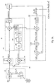
- FIGURE 2A is a block diagram of a downlink RAKE receiver 30 with optional reserving main paths and data signal reconstruction.
- the downlink RAKE receiver 30 includes a pilot signal spreading code matched filter 62, a pilot interference cancellation unit 64, a data signal spreading code matched filter 66, a channel matched filter 68, and a decision unit 70.
- the signal R[k] is transmitted from the FFT unit 28 to the pilot signal spreading code matched filter 62.
- the pilot signal spreading code matched filter 62 removes (despreads) the pilot signal spreading code and includes a multiplier 72, a complex conjugate unit 74, and a unit 76 for storing the FIT of the pilot signal spreading code c p [n].
- the FFT of c p [n] is C p [k], which can be stored in a ROM within the unit 76.
- the complex conjugate unit 74 computes the complex conjugate of the C p [k] to produce C * / p [k].
- the product of R[k] and C * / p[k] produced by the multiplier 72 removes the pilot signal spreading code to produce R[k]C * / p[k].
- the R[k] is also transmitted to the pilot interference cancellation unit 64.
- the pilot interference cancellation unit 64 includes a pilot signal estimation unit 80 and an adder 82.
- the pilot signal estimation unit 80 estimates the pilot interference signal [k] and is described in more detail in FIGURES 4A and 4B below.
- the adder 82 subtracts [k] from the R[k] signal to cancel the pilot interference to produce R1[k].
- a data signal reconstruction component 84 is an optional component that is coupled to the pilot estimation unit 80 for removing data signal effect and is described in more detail below in FIGURE 5.
- the data signal spreading code matched filter 66 operates similarly to the pilot signal spreading code matched filter 62 but removes (despreads) the data signal spreading code from R1[k] received from the pilot interference cancellation unit 64.
- the data signal spreading code matched filter 66 includes a multiplier 88, a complex conjugate unit 90, and a storage unit 92.
- the storage unit 92 stores the FFT of the data signal spreading code c d [n] which is C d [k] and can be stored in a ROM.
- the complex conjugate unit 90 computes the complex conjugate of the C d [k] to produce C * / d [k].
- the multiplier 88 multiplies the R1[k] with C * / d[k] to produce R1[k]C * / d[k].
- the channel matched filter 68 combines the received data signal power from different paths before a decision is made.
- the channel matched filter 68 contains a channel frequency response estimation unit 94, a multiplier 96, and a block sum unit 98.
- the channel frequency response estimation unit 94 includes a complex conjugate unit 100, a delay unit 102, a block-by-block average unit 104, and an optional reserve main paths unit 106.
- the signal R[k]C * / p[k] from the pilot signal spreading code matched filter 62 is transmitted to the channel frequency response estimation unit 94.
- the R[k]C * / p[k] is delayed at the delay unit 102 for one spreading code period.
- average unit 104 computes a weighted block-by-block average of the delayed version of the R[k]C * / p[k]. to generate a channel frequency response estimation [k], where the block period is one spreading code period.
- the complex conjugate unit 100 computes the complex conjugate of the [k] to produce [k].
- the multiplier 96 multiplies the R1[k]C * / d[k] from the data signal spreading code matched filter 66 with [k] to produce R1[k]C * / d[k] [k].
- the block sum unit 98 computes the total sum of the R1[k]C * / d[k] [k] within one spreading code period, which is denoted by ⁇ R 1[ k ] C * / d [ k ] [ k ].
- the decision unit 70 receives ⁇ R 1[ k ] C * / d [ k ] [ k ] from the channel matched filter 68 and makes a data decision. If the data modulation of the data signal is BPSK, the decision unit determines whether the real part of the ⁇ R 1[ k ] C * / d [ k ] [ k ] is greater or less than 0. If the data modulation of the data signal is QPSK, the decision unit determines whether the real part of the ⁇ R 1[ k ] C * / d [ k ] [ k ] and the imaginary part of the ⁇ R 1[ k ] C * / d [ k ] [ k ] are greater or less than 0.
- FIGURE 2B is a block diagram of an alternate downlink RAKE receiver 108 with optional reserving main paths.
- pilot signal estimation unit 80 is also coupled to multiplier 72.
- the delay unit 102 and the average unit 104 are no longer necessary in the channel frequency response estimation unit 94, because, as will be described later, the pilot signal estimation unit 80 already includes these components.
- FIGURE 3A is a block diagram of an uplink RAKE receiver with optional reserve main paths.
- the uplink RAKE receiver. as shown in FIGURE 1B, can detect L number of users at the same time. Each user has the same type of the uplink CDMA RAKE receiver 50. That is, the L users share the same units from the antenna 42 to the FFT units 48, and then R[k] is transmitted to the L uplink CDMA receivers 50 for the L users detection.
- the uplink receiver 50 is implemented using a multi-stage parallel interference cancellation method to increase the system capacity.
- the multi-stage interference cancellation method is an iterative process. At each stage, the reconstructed interference signals generated by the uplink receivers 50 of other users at the previous stage of operation is subtracted from R[k] for each user. Then, the signal remaining after interference cancellation is used for data detection. After data detection, the reconstructed interference signal is generated at each users' uplink receiver and provided to the other users' uplink receivers for the next stage detection process.
- the uplink receiver 50 includes a multi-user interference cancellation unit 110, a data signal spreading code matched filter 112, a channel matched filter 114, a decision unit 116, an interference signal estimation unit 118, and a pilot signal spreading code matched filter 120.
- a multi-user interference cancellation unit 110 receives a data signal from a base station.
- a data signal spreading code matched filter 112 receives a data signal from a base station.
- a channel matched filter 114 a channel matched filter 114
- a decision unit 116 a channel matched filter 114
- an interference signal estimation unit 118 includes a pilot signal spreading code matched filter 120.
- the multi-user interference cancellation unit 110 removes the reconstructed interference signals from other users from the signal R[k] by using a first adder 122 and a second adder 124 to generate the signal remaining after multi-user interference cancellation which is denoted by R1 j [k].
- the index i of R1 i [k] is the i'th stage of data defection of the present received symbol.
- the first adder 122 combines the reconstructed interference signals from other users to generate the total reconstructed interference signal represented by where In j,i-1 [k] is the reconstructed interference signal generated by the uplink receiver of the j'th user at the i-1 stage of data detection.
- the second adder 124 subtracts the signal from the signal R[k] to produce a signal R1 i [k].
- the signal R1 i [k] is represented by the following equation:
- the R1 i [k] is transmitted through the data signal spreading code matched filter 112, and a channel matched filter 114.
- the data signal spreading code matched filter 112 removes (despreads) the data signal spreading code to produce R 1 i [ k ] C * / d [ k ].
- the data signal spreading code matched filter 112 is described in more detail above with respect to FIGURE 2A.
- the signal R 1 i [ k ] C * / d [ k ] from the data signal spreading code matched filter 112 is transmitted to the channel matched filter 114.
- switch 126 closes, thereby allowing the pilot signal spreading code matched filter 120 to produce R 1 M [ k ] C * / p [ k ] and send it to the channel matched filter 114.
- the channel matched filter 114 includes a channel frequency response estimation unit 128, a multiplier 130, and a block sum unit 132.
- the channel frequency response estimation unit 128 includes a delay unit 136, an average unit 138, an optional reserve main paths unit 140, and a complex conjugate unit 142.
- the delay unit 136 delays its received signal until the beginning of the next symbol processing.
- the complex conjugate unit 142 computes the complex conjugate of the [ k ] to produce [ k ].
- the multiplier 130 multiplies the R 1 i [ k ] C * / d [ k ] from the data signal spreading code matched filter 112 with [k] from the complex conjugate unit 142 to produce the R 1 i [ k ] C * / d [ k ] [ k ].
- the block sum unit 132 computes the total sum of the R 1 i [ k ] C * / d [ k ] [ k ] within one spreading code period, which is denoted by the symbol ⁇ R 1 i [ k ] C * / d [ k ] [ k ].
- the decision unit 116 receives the block sum from the channel matched filter 114 and makes a data decision. If the data modulation of the data signal is BFSK, the decision unit determines whether the real part of the ⁇ R 1 i [ k ] C * / d [ k ] [ k ] is greater or less than 0 and generates a tentative decision d 1,i of the present received symbol.
- the decision unit determines whether the real part of the ⁇ R 1 i [ k ] C * / d [ k ] [ k ] and the imaginary part of the ⁇ R 1 i [ k ] C * / d [ k ] [ k ] is greater or less than 0 and generates a tentative decision d 1,i .
- the generated tentative decision d 1,i is a complex signal.
- the signal [k] from the channel frequency response estimation unit 128 and the tentative decision d 1,i of the present symbol from the decision unit 116 are transmitted to an interference signal estimation unit 118 for producing the reconstructed interference signal.
- the interference signal estimation unit 118 is used to reconstruct the transmitted symbol of the user, which is the multiple access interference of user 1 to be used by the other users' uplink receivers.
- the reconstructed interference signal of user 1 is transmitted to the other users' uplink receivers for multi-user interference cancellation.
- the interference signal estimation unit 118 includes a first multiplier 150, an adder 152, a second multiplier 154, and a normalization unit 155.
- the first multiplier 150 multiplies the FFT of the data signal spreading code C d [k] with the signal d 1,i from the decision unit 116 to generate the data modulated data signal spreading code C d [k]d 1,i .
- the adder 152 combines the FFT of the pilot signal spreading code with the signal C d [k]d 1,i to generate C p [ k ] + C d [ k ] ⁇ d 1, i ..
- the second multiplier 154 multiplies the C p [ k ] + C d [ k ] ⁇ d 1, i from the adder 152 with the [ k ] from the channel frequency response estimation unit 128 to produce ( C p [ k ]+ C d [ k ] ⁇ d 1, i ) ⁇ [ k ]. Since the channel frequency response estimation [ k ] is weighted by the C p [ k ] 2 due to the pilot signal spreading code matched filter 120, the normalization unit 155 is used to remove the weighting factor C p [ k ] 2 .
- the normalization unit 155 normalizes the output of the second multiplier 154 by C p [ k ] 2 to generate the reconstructed interference signal denoted by the In 1,i [k].
- the signal In 1,i [k] is represented by the following equation:
- the uplink RAKE receiver 50 does M stages of data detection for each received symbol, that is, after M times of data detection, the uplink receiver will process the next symbol for data detection in a similar way.
- the switch 126 closes and the signal R1 M [k] is transmitted from the multi-user interference cancellation unit 110 to the pilot signal spreading code matched filter 120.
- the pilot signal spreading code matched filter 120 removes (despreads) the pilot signal spreading code and produces a R M [ k ] C * / p [ k ] signal.
- the signal R M [ k ] C * / p [ k ] is transmitted to the channel frequency response estimation unit 128 within the channel matched filter 114 for channel frequency response estimation.
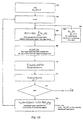
- FIGURE 3B is a non-user specific data detection flowgraph (use user n as an example) of the uplink receiver shown in FIGURE 3A.
- the receiver 50 gets or receives the reconstructed interference signals In j,i-1 [k] generated from other users.
- the uplink receiver of user n does not receive the reconstructed interference signal (In j,0 [k]) from other users.
- the uplink receiver of user n sets the reconstructed interference signal (In j,0 [k]) to 0 at the first stage of data detection of the present received symbol.
- the uplink receiver of the user n receives the reconstructed interference signals from other users which are generated at the previous stage of data detection.
- the reconstructed interference signals from other users are subtracted from R[k] as stated in the following equation:
- R1 i [k] is multiplied with the complex conjugate of the FFT of data signal spreading code to generate R 1 i [ k ] C * / d [ k ].
- the output of the step 168 is matched to the channel frequency response estimation to generate ⁇ R 1 i [ k ] C * / d [ k ] [ k ].
- a tentative decision d n,i is made for the present received symbol. If at decision step 174 the i'th data detection stage equals the last stage of data detection M, the tentative decision is d n,M .
- the reconstructed interference signal of user n at the i'th stage of data detection is computed and then sent to the uplink receivers of the other users, where the reconstructed interference signal of the users n is represented by the equation
- the data detection process is then looped back to the step 162 where the index i is incremented by one for the next stage data detection of the present received symbol.
- FIGURE 4A illustrates a pilot signal estimation unit 180 for low speed users.
- the received R[k] signal is delayed at a delay unit 182 for one spreading code period. Since the pilot signal is fixed, that is, it is unmodulated, a simple block-by-block average of the R[k] estimates the pilot interference.
- An average unit 184 then computes a weighted block-by-block average of the R[k] signal to generate the pilot interference [k], where the block period is one spreading code period. This setup is effective in a low speed system, because the averaging can be performed over a long period of time.
- FIGURE 4B illustrates a pilot signal estimation unit 186 for high speed users.
- a summer 188 is included between the delay unit and the average unit.
- the summer 188 removes data signal component from the delayed signal.
- the data signal component is reconstructed by the data signal reconstruction unit 84 described in FIGURE 5 below. Since the average length of the signal is not large enough with respect to high speed users, the reconstructed data signal component must be removed for pilot signal estimation to avoid "data signal cancellation.”
- the data signal reconstruction unit 84 includes a first and second multiplier 190 and 192 and a normalization unit 194 for reconstructing the data signal using a decision feedback method.
- the first multiplier 190 multiplies the data detection output of the previous received syrnbol d with the FFT of the data signal spreading code C d [k] to generate d ⁇ C d [k] .
- the second multiplier 192 multiplies d ⁇ C d [k] with the channel frequency response estimation [k] that is then normalized by normalization unit 194 to generate the reconstructed data signal component of the previous received symbol,
- the reserve main paths unit 106 includes an Inverse Fast Fourier Transform (IFFT) unit 200, a search peak unit 202, a selecting unit 204, and a FFT unit 206.
- the IFFT unit 200 receives the signal from the pilot signal spreading code matched filter 62 or the average unit 104 or the average unit 138, see FIGURES 2A, 2B and 3A, respectively, and computes the IFFT, thereby generating the channel impulse response estimation denoted by the symbol [n].
- the search peak unit 202 receives [n] from the IFFT unit 200 and searches or determines the peak amplitude of [n].
- the select path unit 204 selects signals with high amplitudes from [n] and discards the remaining signals that have low amplitudes by setting the low amplitude signals to zero.
- a high amplitude signal is typically a signal with an amplitude which is greater than 10dB below the peak value of [n] while a low amplitude signal is typically a signal with a relatively smaller amplitude.
- the selection of high amplitude signals generates a modified channel impulse response estimation signal 1[n] containing only signals on the main paths.
- the FFT unit 206 calculates the FFT transformation of the 1[n] from the selecting unit 204 to generate a channel frequency response estimation [k].
- the [k] provides the coefficient of the channel matched filter 68 and 114.
- the reserve main path unit 106 is not required, but does provide more reliable channel estimation.
Landscapes
- Engineering & Computer Science (AREA)
- Computer Networks & Wireless Communication (AREA)
- Signal Processing (AREA)
- Noise Elimination (AREA)
Claims (26)
- Downlink-Empfänger (30; 108) umfassend:eine Pilotinterferenz-Löschungseinheit (64) zum Subtrahieren von Pilotsignalinterferenz von der FFT eines empfangenen Basisbandsignals vom Typ eines direkten Sequenzspreizspektrums;ein Datensignalspreizungscode-Matched-Filter (66) zum Entfernen von Datensignalspreizungscode von der Ausgabe der Pilotinterferenz-Löschungseinheit (64);ein Pilotsignalspreizungscode-Matched-Filter (62) zum Entfernen von Pilotsignalspreizungscode von der FFT des empfangenen Basisbandsignals;ein Kanal-Matched-Filter (68) zum Erzeugen einer Kanalfrequenzantwortschätzung basierend auf der Ausgabe des Pilotsignalspreizungscode-Matched-Filters (62), zum Erzeugen des Produktes der Ausgabe des Datensignalspreizungscode-Matched-Filters (66) und der konjugiert Komplexen der Kanalfrequenzantwortschätzung und zum Berechnen der Blocksumme des Produktes innerhalb einer Spreizungscodeperiode; undeine Bestimmungseinheit (70) zum Bestimmen des Datenwertes aus der erzeugten Blocksumme basierend auf einem vorher ausgewählten Modulationstyp.
- Downlink-Empfänger (30; 108) nach Anspruch 1, wobei die Pilotinterferenz-Löschungseinheit (64) umfaßt:eine Pilotsignal-Schätzeinheit (80; 180; 186) zum Schätzen der Pilotsignalkomponente aus der FFT des empfangenen Basisbandsignals; undeinen Kombinierer (82) zum Subtrahieren der geschätzten Pilotsignalkomponente von der FFT des empfangenen Basisbandsignals.
- Downlink-Empfänger (30; 108) nach Anspruch 2, wobei die Pilotsignal-Schätzeinheit (180; 186) umfaßt:eine Verzögerungseinheit (182) zum Verzögern der FFT des empfangenen Basisbandsignals um eine Spreizungscodeperiode; undeine Mittelungseinheit (184) zum Durchführen einer gewichteten Block-für-Block Mittelung der verzögerten FFT des empfangenen Basisbandsignals.
- Downlink-Empfänger (30; 108) nach Anspruch 2, wobei die Pilotsignal-Schätzeinheit (186) umfaßt:eine Verzögerungseinheit (182) zum Verzögern der FFT des empfangenen Basisbandsignals um eine Spreizungscodeperiode;eine Datensignal-Rekonstruktionseinheit (84) zum Rekonstruieren der Datensignalkomponente basierend auf dem Konzept einer Datenbestimmungsrückkopplung;ein Pilotsignal-Schätzkombinierer (188) zum Subtrahieren der rekonstruierten Datensignalkomponente von der verzögerten FFT des empfangenen Basisbandsignals; undeine Mittelungseinheit (184) zum Durchführen einer gewichteten Block-für-Block Mittelung des Ergebnisses des Pilotsignal-Schätzkombinierers (188).
- Downlink-Empfänger (30; 108) nach einem der Ansprüche 1 bis 4, wobei das Datensignalspreizungscode-Matched-Filter (66) umfaßt:eine Speichereinheit (92) zum Speichern der FFT eines Datensignalspreizungscodes;eine Konjugiert-Komplex-Einheit (90) zum Berechnen der konjugiert Komplexen der FFT des Datensignalspreizungscodes; undeinen Multiplizierer (88) zum Multiplizieren der Ausgabe der Pilotinterferenz-Löschungseinheit (64) mit der Ausgabe der Konjugiert-Komplex-Einheit (90).
- Downlink-Empfänger (30; 108) nach einem der Ansprüche 1 bis 5, wobei das Pilotsignalspreizungscode-Matched-Filter (62) umfaßt:eine Speichereinheit (76) zum Speichern der FFT eines Pilotsignalspreizungscodes;eine Konjugiert-Komplex-Einheit (74) zum Berechnen der konjugiert Komplexen der FFT des Pilotsignalspreizungscodes; undeinen Multiplizierer (88) zum Multiplizieren der FFT des empfangenen Basisbandsignals mit der Ausgabe der Konjugiert-Komplex-Einheit (90).
- Downlink-Empfänger (30; 108) nach einem der Ansprüche 1 bis 6, wobei das Kanal-Matched-Filter (68) eine Kanalfrequenzantwort-Schätzeinheit (94) zum Erzeugen der Kanalfrequenzantwortschätzung basierend auf der Ausgabe des Pilotsignalspreizungscode-Matched-Filters (62) umfaßt, wobei die Kanalfrequenzantwort-Schätzeinheit (94) umfaßt:eine Verzögerungseinheit (102) zum Verzögern der Ausgabe des Pilotsignalspreizungscode-Matched-Filters (62) um eine Spreizungscodeperiode;eine Mittelungseinheit (104) zum Durchführen einer gewichteten Block-für-Block Mittelung der verzögerten Ausgabe des Pilotsignalspreizungscode-Matched-Filters (62); undeine Konjugiert-Komplex-Einheit (100) zum Berechnen der konjugiert Komplexen der gewichteten Block-für-Block Mittelung der verzögerten Ausgabe des Pilotsignalspreizungscode-Matched-Filters (62).
- Downlink-Empfänger (30; 108) nach Anspruch 7, wobei die Kanalfrequenzantwort-Schätzeinheit (94) eine Hauptfpfad-Belegungseinheit (106) zum Belegen von Hauptpfaden umfaßt, wobei die Hauptfpfad-Belegungseinheit (106) umfaßt:eine Inverse-FFT-Einheit (200) zum Berechnen der inversen FFT der gewichteten Block-für-Block Mittelung der verzögerten Ausgabe des Pilotsignalspreizungscode-Matched-Filters (62), um eine Kanalimpulsantwortschätzung zu erzeugen;eine Sucheinheit (202) zum Finden von Spitzenamplituden der inversen FFT;eine Auswahleinheit (204) zum Erzeugen einer Hauptpfadbelegungs-Kanalimpulsantwortschätzung basierend auf den gefundenen Spitzenamplituden; undeine FFT-Einheit (206) zum Berechnen der FFT der generierten Hauptpfadbelegungs-Kanalimpulsantwortschätzung.
- Downlink-Empfänger (30; 108) nach Anspruch 7, wobei das Kanal-Matched-Filter (68) desweiteren umfaßt:einen Multiplizierer (96) zum Multiplizieren der Ausgabe des Datensignalspreizungscode-Matched-Filters mit der konjugiert Komplexen der Kanalfrequenzantwortschätzung; undeinen Summierer (98) zum Berechnen einer Blocksumme der Ausgabe des Multiplizierers innerhalb einer Spreizungscodeperiode.
- Ein Verfahren zum Downlink-Empfangen, wobei das Verfahren umfaßt:Subtrahieren von Pilotsignalinterferenz von der FFT eines empfangenen Basisbandsignals vom Typ eines direkten Sequenzspreizspektrums;Entfernen eines Datensignalspreizungscodes von der FFT eines empfangenen Basisbandsignals nach der Pilotsignal-Interferenzsubtraktion;Entfernen eines Pilotsignalspreizungscodes von der FFT des empfangenen Basisbandsignals;Erzeugen einer Kanalfrequenzantwortschätzung aus der FFT des empfangenen Basisbandsignals nach Entfernen des Pilotsignalspreizungscodes;Erzeugen des Produktes der konjugiert Komplexen der Kanalfrequenzantwortschätzung und der FFT des empfangenen Basisbandsignals nach der Pilotsignal--Interferenzsubtraktion und Entfernen des Datensignalspreizungscodes;Berechnen der Blocksumme des Produktes innerhalb einer Spreizungscodeperiode; undBestimmen des Datenwertes aus dem summierten Wert basierend auf einem vorher ausgewählten Modulationstyp.
- Verfahren nach Anspruch 10, wobei das Subtrahieren von Pilotsignalinterferenz von der FFT eines empfangenen Basisbandsignals umfaßt:Schätzen der Pilotsignalkomponente aus der FFT des empfangenen Basisbandsignals; undSubtrahieren der geschätzten Pilotsignalkomponente von der FFT des empfangenen Basisbandsignals.
- Verfahren nach Anspruch 11, wobei das Schätzen der Pilotsignalkomponete umfaßt:Verzögern der FFT des empfangenen Basisbandsignals um eine Spreizungscodeperiode; undDurchführen einer gewichteten Block-für-Block Mittelung der verzögerten FFT des empfangenen Basisbandsignals.
- Verfahren nach Anspruch 11, wobei das Schätzen der Pilotsignalkomponete umfaßt:Rekonstruieren der Datensignalkomponente aus einem vorher empfangenen Symbol;Verzögern der FFT des empfangenen Basisbandsignals um eine Spreizungscodeperiode;Subtrahieren der rekonstruierten Datensignalkomponente von der verzögerten FFT des empfangenen Basisbandsignals; undDurchführen einer gewichteten Block-für-Block Mittelung der verzögerten FFT des empfangenen Basisbandsignals nach der Subtraktion der rekonstruierten Datensignalkomponente.
- Verfahren nach einem der Ansprüche 10 bis 13, wobei das Entfernen des Datensignalspreizungscodes von der FFT des empfangenen Basisbandsignals nach der Pilotsignalinterferenz-Subtraktion umfaßt:Erzeugen der FFT eines Datensignalspreizungscodes;Berechnen des konjugiert Komplexen der FFT des Datensignalspreizungscodes; undMultiplizieren der berechneten konjugiert Komplexen mit der FFT eines empfangenen Basisbandsignals nach der Pilotsignalinterferenz-Subtraktion.
- Verfahren nach einem der Ansprüche 10 bis 14, wobei das Entfernen des Pilotsignalspreizungscodes von der FFT des empfangenen Basisbandsignals umfaßt:Erzeugen der FFT eines Pilotsignalspreizungscodes;Berechnen der konjugiert Komplexen der FFT des Pilotsignalspreizungscodes; undMultiplizieren der FFT des empfangenen Basisbandsignals mit der berechneten konjugiert Komplexen.
- Verfahren nach einem der Ansprüche 10 bis 15, wobei das Erzeugen der Kanalfrequenzantwortschätzung umfaßt:Verzögern der FFT des empfangenen Basisbandsignals um eine Spreizungscodeperiode nach dem Entfernen des Pilotsignalspreizungscode;Durchführen einer gewichteten Block-für-Block Mittelung der verzögerten FFT des empfangenen Basisbandsignals nach Entfernen des Pilotsignalspreizungscodes; undBerechnen der konjugiert Komplexen der gewichteten Block-für-Block Mittelung.
- Verfahren nach Anspruch 16, wobei das Erzeugen der Kanalfrequenzantwortschätzung desweiteren ein Belegen von Hauptpfaden umfaßt und wobei das Belegen von Hauptpfaden umfaßt:Berechnen einer inversen FFT der gewichteten Block-für-Block Mittelung der verzögerten FFT des empfangenen Basisbandsignals nach Entfernen des Pilotsignalspreizungscodes, um eine Kanalimpulsantwortschätzung zu erzeugen;Finden der Spitzenamplituden der berechneten inversen FFT;Erzeugen einer Hauptpfadbelegungs-Kanalimpulsantwortschätzung basierend auf den gefundenen Spitzenamplituden;Berechnen der FFT der erzeugten Hauptpfadbelegungs-Kanalimpulsantwortschätzung.
- Verfahren nach einem der Ansprüche 10 bis 17, wobei das Summieren des Produktes der konjugiert Komplexen der Kanalfrequenzantwortschätzung und der FFT des empfangenen Basisbandsignals innerhalb einer Spreizungscodeperiode nach der Pilotsignal-Interferenzsubtraktion und das Entfernen des Datensignalspreizungscodes desweiteren umfassen:Multiplizieren der konjugiert Komplexen der Kanalfrequenzantwortschätzung mit der FFT des empfangenen Basisbandsignals nach Pilotsignal-Interferenzsubtraktion und Entfernen des Datensignalspreizungscodes; undDurchführen einer Blocksumme des Produktes innerhalb einer Spreizungscodeperiode.
- Ein Uplink-Empfänger (50) zur iterativen Mehrstufen-Datendetektion von empfangenen Symbolen, umfassend:eine Mehrbenutzer-Interferenzlöschungseinheit (110) zum Subtrahieren geschätzter Interferenzsignale anderer Benutzer auf einer vorherigen Stufe der iterativen Mehrstufen-Datendetektion von einer FFT eines empfangenen Basisbandsignals von Typ eines direkten Sequenzspreizspektrums;ein Datensignalspreizungscode-Matched-Filter (112) zum Entfernen eines Datensignalspreizungscodes von der FFT eines empfangenen Basisbandsignals nach Subtraktion geschätzter Interferenzsignale;ein Pilotsignalspreizungscode-Matched-Filter (120) zum Entfernen eines Pilotsignalspreizungscodes von der FFT des empfangenen Basisbandsignals nach Subtraktion geschätzter Interferenzsignale;ein zwischen der Mehrbenutzer-Interferenzlöschungseinheit (110) und dem Pilotsignalspreizungscode-Matched-Filter (120) angeschlosser Schalter (126), der betriebsbereit ist, geschlossen zu werden, wenn die letzte Stufe der iterativen Datendetektion des vorliegenden empfangenen Symbols erreicht wird;ein Kanal-Matched-Filter (114) zum Erzeugen einer Kanalfrequenzantwortschätzung basierend auf der Ausgabe des Pilotsignalspreizungscode-Matched-Filters (120), zum Erzeugen des Produkts der Ausgabe des Datensignalspreizungscode-Matched-Filters (112) und der konjugiert Komplexen der Kanalfrequenzantwortschätzung und zum Berechnen der Blocksumme des Produktes innerhalb einer Spreizungscodeperiode;eine Bestimmungseinheit (116) zum Bestimmen eines vorläufigen Datenwertes und eines endgültigen Datenwertes aus der erzeugten Blocksumme basierend auf einem vorher ausgewählten Modulationstyp; undeine Interferenzsignal-Schätzeinheit (118) zum Erzeugen eines geschätzten Interferenzsignals zur Interferenzlöschung duch andere Benutzer basierend auf der Kanalfrequenzantwortschätzung, den FFTs der Pilot- und Datensignalspreizungscodes und dem bestimmten vorläufigen Datenwertes.
- Uplink--Empfänger (50) nach Anspruch 19, wobei die Mehrbenutzer-Interferenzlöschungseinheit (110) umfaßt:einen ersten Addierer (122) zum Summieren der geschätzten Interferenzsignale von anderen Empfängern; undeinen zweiten Addierer (124) zum Subtrahieren des summierten geschätzten Interferenzsignals von der FFT des empfangenen Basisbandsignals.
- Uplink-Empfänger (50) nach Anspruch 19 oder 20, wobei das Datensignalspreizungscode-Matched-Filter (112) umfaßt:eine Speichereinheit zum Speichern der FFT eines Datensignalspreizungscodes;eine Konjugiert-Komplex-Einheit zum Berechnen der konjugiert Komplexen der FFT des Datensignalspreizungscodes; undeinen Multiplizierer zum Multiplizieren der Ausgabe der Mehrbenutzer-Interferenzlöschungseinheit (110) mit der Ausgabe der Konjugiert-Komplex-Einheit.
- Uplink-Empfänger (50) nach einem der Ansprüche 19 bis 21, wobei das Pilotsignalspreizungscode-Matched-Filter (120) umfaßt:eine Speichereinheit zum Speichern der FFT eines Pilotsignalspreizungscodes;eine Konjugiert-Komplex-Einheit zum Berechnen der konjugiert Komplexen der FFT des Pilotsignalspreizungscodes; undeinen Multiplizierer zum Multiplizieren der Ausgabe der Mehrlbenutzer-Interferenzlöschungseinheit (110) auf der letzten Stufe der Datendetektion mit der konjugiert Komplexen der FFT des Pilotsignalspreizungscodes.
- Uplink--Empfänger (50) nach einem der Ansprüche 19 bis 22, wobei das Kanal-Matched-Filter (114) eine Kanalfrequenzantwort-Schätzeinheit (128) zum Erzeugen der Kanalfrequenzantwortschätzung basierend auf der Ausgabe des Pilotsignalspreizungscode-Matched-Filters (120) umfaßt, wobei die Kanalfrequenzantwort-Schätzeinheit (128) umfaßt:eine Verzögerungseinheit (136) zum Verzögern der Ausgabe des Pilotsignalspreizungscode-Matched-Filters (120) um eine Spreizungscodeperiode;eine Mittelungseinheit (138) zum Durchführen einer gewichteten Block-für-Block Mittelung der verzögerten Ausgabe des Pilotsignalspreizungscode-Matched-Filters (120); undeine Konjugiert-Komplex-Einheit (142) zur Berechnung der konjugiert Komplexen der gewichteten Block-für-Block Mittelung der verzögerten Ausgabe des Pilotsignalspreizungscode-Matched-Filters (120).
- Uplink-IEmpfänger (50) nach Anspruch 23, wobei die Kanatfrequenzantwort-Schätzeinheit (128) eine Hauptpfad-Belegungseinheit (140) zum Belegen von Hauptpfaden umfaßt, wobei die Hauptpfad-Belegungseinheit (140) umfaßt:eine Inverse-FFT-Einheit (200) zum Berechnen einer inversen FFT der gewichteten Block-für-Block Mittelung der verzögerten Ausgabe des Pilotsignalspreizungscode-Matched-Filters (120) um eine Kanalimpulsantwortschätzung zu erzeugen;eine Sucheinheit (202) zum Finden von Spitzenamplituden der inversen FFT;eine Auswahleinheit (204) zum Erzeugen einer Hauptpfadbelegungs-Kanalimpulsantwortschätzung basierend auf den gefundenen Spitzenamplituden; undeine FFT-Einheit (206) zum Berechnen der FFT der generierten Hauptpfadbelegungs-Kanalimpulsantwortschätzung.
- Uplink--Empfänger (50) nach Anspruch 23, wobei das Kanal-Matched-Filter (114) desweiteren umfaßt:einen Multiplizierer (130) zum Multiplizieren der Ausgabe des Datensignalspreizungscode-Matched-Filters mit der konjugiert Komplexen der Kanalfrequenzantwortschätzung; undeinen Summierer (132) zum Berechnen einer Blocksumme der Ausgabe des Multiplizierers innerhalb einer Spreizungscodeperiode.
- Uplink-Empfänger (50) nach Anspruch 19, wobei die Interferenzsignal-Schätzeinheit (118) umfaßt:einen ersten Multiplizierer (150) zum Multiplizieren der FFT des Datensignalspreizungscodes mit der vorläufigen Datenbestimmung;einen Addierer (152) zum Summieren der Ausgabe des ersten Multiplizierers mit der FFT des Pilotsignalspreizungscodes;einen zweiten Multiplizierer (154) zum Multiplizieren der Kanalfirequenzantwortschätzung mit dem Ergebnis des Addierers (152); undeine Normalisierungseinheit (155) zum Normalisieren der Ausgabe des zweiten Multiplizierers (154) mit der Quadratnorm der FFT des Pilotsignalspreizungscodes.
Applications Claiming Priority (2)
| Application Number | Priority Date | Filing Date | Title |
|---|---|---|---|
| US132859 | 1993-10-07 | ||
| US09/132,859 US6154443A (en) | 1998-08-11 | 1998-08-11 | FFT-based CDMA RAKE receiver system and method |
Publications (3)
| Publication Number | Publication Date |
|---|---|
| EP0980149A2 EP0980149A2 (de) | 2000-02-16 |
| EP0980149A3 EP0980149A3 (de) | 2003-03-19 |
| EP0980149B1 true EP0980149B1 (de) | 2004-10-20 |
Family
ID=22455919
Family Applications (1)
| Application Number | Title | Priority Date | Filing Date |
|---|---|---|---|
| EP99114418A Expired - Lifetime EP0980149B1 (de) | 1998-08-11 | 1999-07-22 | CDMA Rake-Empfängersystem und Verfahren auf FFT-Basis |
Country Status (4)
| Country | Link |
|---|---|
| US (1) | US6154443A (de) |
| EP (1) | EP0980149B1 (de) |
| DE (1) | DE69921248T2 (de) |
| TW (1) | TW419912B (de) |
Cited By (5)
| Publication number | Priority date | Publication date | Assignee | Title |
|---|---|---|---|---|
| US7903770B2 (en) | 2001-06-06 | 2011-03-08 | Qualcomm Incorporated | Method and apparatus for canceling pilot interference in a wireless communication system |
| US8099123B2 (en) | 2004-12-23 | 2012-01-17 | Qualcomm Incorporated | Adaptation of transmit subchannel gains in a system with interference cancellation |
| US8406695B2 (en) | 2004-12-23 | 2013-03-26 | Qualcomm Incorporated | Joint interference cancellation of pilot, overhead and traffic channels |
| US8422955B2 (en) | 2004-12-23 | 2013-04-16 | Qualcomm Incorporated | Channel estimation for interference cancellation |
| US8442441B2 (en) | 2004-12-23 | 2013-05-14 | Qualcomm Incorporated | Traffic interference cancellation |
Families Citing this family (137)
| Publication number | Priority date | Publication date | Assignee | Title |
|---|---|---|---|---|
| US7027490B2 (en) * | 1997-06-11 | 2006-04-11 | Intel Corporation | Method and apparatus for reducing spread spectrum noise |
| US7430257B1 (en) | 1998-02-12 | 2008-09-30 | Lot 41 Acquisition Foundation, Llc | Multicarrier sub-layer for direct sequence channel and multiple-access coding |
| US5955992A (en) * | 1998-02-12 | 1999-09-21 | Shattil; Steve J. | Frequency-shifted feedback cavity used as a phased array antenna controller and carrier interference multiple access spread-spectrum transmitter |
| US6498784B1 (en) * | 1998-10-20 | 2002-12-24 | Interdigital Technology Corporation | Cancellation of pilot and traffic signals |
| DE60042812D1 (de) * | 1999-01-22 | 2009-10-08 | Konica Minolta Opto Inc | Optische Abtastvorrichtung, mit der optischen Abtastvorrichtung versehenes Aufnahme/Wiedergabegerät, optisches Element und Verfahren zur Datenaufnahme/wiedergabe |
| US6765969B1 (en) * | 1999-09-01 | 2004-07-20 | Motorola, Inc. | Method and device for multi-user channel estimation |
| US6278726B1 (en) * | 1999-09-10 | 2001-08-21 | Interdigital Technology Corporation | Interference cancellation in a spread spectrum communication system |
| US6115406A (en) * | 1999-09-10 | 2000-09-05 | Interdigital Technology Corporation | Transmission using an antenna array in a CDMA communication system |
| FR2805943B1 (fr) * | 1999-09-14 | 2002-08-09 | Inst Nat Sciences Appliq | Procede d'egalisation dans des recepteurs utilisant une combinaison des techniques de modulations a porteuses multiples et a acces multiple par repartition de codes |
| EP1117186A1 (de) * | 2000-01-14 | 2001-07-18 | Lucent Technologies Inc. | Adaptiver Kodenachlauf-RAKE-Empfänger für CDMA-Nachrichtenübertragung |
| EP1117185A1 (de) * | 2000-01-14 | 2001-07-18 | Lucent Technologies Inc. | Verfahren und RAKE-Empfänger zur Kodenachführung in einem CDMA-Nachrichtenübertragungssystem |
| EP1130792A1 (de) * | 2000-03-03 | 2001-09-05 | Lucent Technologies Inc. | Verfahren und Rake-empfänger für Phasenvektorschätzung in Kommunikationssystemen |
| EP1143630B1 (de) * | 2000-04-07 | 2004-06-16 | Alcatel | Empfänger für ein CDMA Mobilfunkkommunikationssystem |
| JP3407711B2 (ja) * | 2000-04-27 | 2003-05-19 | 日本電気株式会社 | Ds−cdma方式の受信機におけるパスサーチ回路 |
| EP1329119A1 (de) * | 2000-09-21 | 2003-07-23 | Telefonaktiebolaget LM Ericsson (publ) | Verfahren und benutzergerät zur identifizierung von transportblöcken, die nicht an das benutzergerät gerichtet sind |
| JP3415579B2 (ja) * | 2000-11-09 | 2003-06-09 | 松下電器産業株式会社 | マッチドフィルタおよび相関検出演算方法 |
| GB2369018A (en) * | 2000-11-10 | 2002-05-15 | Ubinetics Ltd | Control channel interference cancellation for a CDMA receiver |
| US8670390B2 (en) | 2000-11-22 | 2014-03-11 | Genghiscomm Holdings, LLC | Cooperative beam-forming in wireless networks |
| US6711219B2 (en) | 2000-12-04 | 2004-03-23 | Tensorcomm, Incorporated | Interference cancellation in a signal |
| US6856945B2 (en) | 2000-12-04 | 2005-02-15 | Tensorcomm, Inc. | Method and apparatus for implementing projections in singal processing applications |
| DE60121911T2 (de) * | 2001-01-15 | 2007-01-18 | Lucent Technologies Inc. | Verfahren zur Maximum-Likelihood-Bestimmung unter Verwendung eines Empfängers mit Sequenzschätzung |
| US7751469B2 (en) | 2001-02-20 | 2010-07-06 | Massachusetts Institute Of Technology | Correlation shaping matched filter receiver |
| US7636403B2 (en) | 2001-02-20 | 2009-12-22 | Massachusetts Institute Of Technology | Correlation shaping multi-signature receiver |
| US7376175B2 (en) * | 2001-03-14 | 2008-05-20 | Mercury Computer Systems, Inc. | Wireless communications systems and methods for cache enabled multiple processor based multiple user detection |
| US7110431B2 (en) * | 2001-03-14 | 2006-09-19 | Mercury Computer Systems, Inc. | Hardware and software for performing computations in a short-code spread-spectrum communications system |
| US7697594B2 (en) * | 2001-03-30 | 2010-04-13 | Texas Instruments Incorporated | Method and apparatus for regenerative based interference cancellation within a communication system |
| US7027489B2 (en) * | 2001-04-06 | 2006-04-11 | Interdigital Technology Corporation | Iterative fast fourier transform error correction |
| US9819449B2 (en) | 2002-05-14 | 2017-11-14 | Genghiscomm Holdings, LLC | Cooperative subspace demultiplexing in content delivery networks |
| US10931338B2 (en) | 2001-04-26 | 2021-02-23 | Genghiscomm Holdings, LLC | Coordinated multipoint systems |
| US9893774B2 (en) | 2001-04-26 | 2018-02-13 | Genghiscomm Holdings, LLC | Cloud radio access network |
| US10355720B2 (en) | 2001-04-26 | 2019-07-16 | Genghiscomm Holdings, LLC | Distributed software-defined radio |
| US10425135B2 (en) | 2001-04-26 | 2019-09-24 | Genghiscomm Holdings, LLC | Coordinated multipoint systems |
| US8611311B2 (en) | 2001-06-06 | 2013-12-17 | Qualcomm Incorporated | Method and apparatus for canceling pilot interference in a wireless communication system |
| US20050013350A1 (en) * | 2001-06-06 | 2005-01-20 | Coralli Alessandro Vanelli | Method and apparatus for canceling pilot interference in a wireless communication system |
| US8085889B1 (en) | 2005-04-11 | 2011-12-27 | Rambus Inc. | Methods for managing alignment and latency in interference cancellation |
| US7158559B2 (en) | 2002-01-15 | 2007-01-02 | Tensor Comm, Inc. | Serial cancellation receiver design for a coded signal processing engine |
| CN1155189C (zh) | 2001-10-09 | 2004-06-23 | 华为技术有限公司 | 双层加权并行干扰对消方法的简化方法 |
| US20030072282A1 (en) * | 2001-10-17 | 2003-04-17 | Ying-Chang Liang | Code division multiple access downlink receiver |
| US6661809B2 (en) * | 2001-11-14 | 2003-12-09 | Motorola, Inc. | Methods and communications terminals for increasing capacity CDMA communications networks |
| US7200183B2 (en) | 2001-11-16 | 2007-04-03 | Tensorcomm Inc. | Construction of an interference matrix for a coded signal processing engine |
| WO2005081438A1 (en) * | 2001-11-19 | 2005-09-01 | Tensorcomm, Incorporated | Interference cancellation in a signal |
| US7430253B2 (en) | 2002-10-15 | 2008-09-30 | Tensorcomm, Inc | Method and apparatus for interference suppression with efficient matrix inversion in a DS-CDMA system |
| US7260506B2 (en) | 2001-11-19 | 2007-08-21 | Tensorcomm, Inc. | Orthogonalization and directional filtering |
| US6640088B2 (en) * | 2001-12-14 | 2003-10-28 | Motorola, Inc. | Method and system for adaptive channel estimation techniques |
| US7058134B2 (en) * | 2001-12-17 | 2006-06-06 | Intel Corporation | System and method for multiple signal carrier time domain channel estimation |
| DE60214772T2 (de) * | 2002-01-07 | 2007-09-06 | Koninklijke Philips Electronics N.V. | Rake-empfänger mit individuellem fingerkompensator |
| US7324584B1 (en) * | 2002-01-31 | 2008-01-29 | Nortel Networks Limited | Low complexity interference cancellation |
| US20030162573A1 (en) * | 2002-02-19 | 2003-08-28 | Jyhchau Horng | Down-link interference cancellation for high-data-rate channels in advanced digital wireless networks |
| US10200227B2 (en) | 2002-05-14 | 2019-02-05 | Genghiscomm Holdings, LLC | Pre-coding in multi-user MIMO |
| US10142082B1 (en) | 2002-05-14 | 2018-11-27 | Genghiscomm Holdings, LLC | Pre-coding in OFDM |
| US9628231B2 (en) | 2002-05-14 | 2017-04-18 | Genghiscomm Holdings, LLC | Spreading and precoding in OFDM |
| US10644916B1 (en) | 2002-05-14 | 2020-05-05 | Genghiscomm Holdings, LLC | Spreading and precoding in OFDM |
| CN100336325C (zh) * | 2002-06-19 | 2007-09-05 | 上海贝尔有限公司 | 瑞克接收机信道估计方法 |
| US7061967B2 (en) * | 2002-06-24 | 2006-06-13 | Comsys Communication & Signal Processing Ltd. | Multipath channel tap delay estimation in a CDMA spread spectrum receiver |
| US7573958B2 (en) * | 2002-07-18 | 2009-08-11 | Motorola, Inc. | Receiver for and method of recovering transmitted symbols in a H-ARQ packet retransmission |
| US8194770B2 (en) | 2002-08-27 | 2012-06-05 | Qualcomm Incorporated | Coded MIMO systems with selective channel inversion applied per eigenmode |
| US7876810B2 (en) | 2005-04-07 | 2011-01-25 | Rambus Inc. | Soft weighted interference cancellation for CDMA systems |
| US7808937B2 (en) | 2005-04-07 | 2010-10-05 | Rambus, Inc. | Variable interference cancellation technology for CDMA systems |
| US8761321B2 (en) | 2005-04-07 | 2014-06-24 | Iii Holdings 1, Llc | Optimal feedback weighting for soft-decision cancellers |
| US7463609B2 (en) | 2005-07-29 | 2008-12-09 | Tensorcomm, Inc | Interference cancellation within wireless transceivers |
| US7787572B2 (en) | 2005-04-07 | 2010-08-31 | Rambus Inc. | Advanced signal processors for interference cancellation in baseband receivers |
| US7577186B2 (en) | 2002-09-20 | 2009-08-18 | Tensorcomm, Inc | Interference matrix construction |
| US8005128B1 (en) | 2003-09-23 | 2011-08-23 | Rambus Inc. | Methods for estimation and interference cancellation for signal processing |
| EP1550233B1 (de) | 2002-09-23 | 2012-11-07 | Rambus Inc. | Verfahren und Vorrichtung zum selektiven Anwenden von Störungslöschung in Spreizspektrumsystemen |
| US8179946B2 (en) | 2003-09-23 | 2012-05-15 | Rambus Inc. | Systems and methods for control of advanced receivers |
| EP1579591B1 (de) | 2002-10-15 | 2012-06-06 | Rambus Inc. | Verfahren und vorrichtung zur kanalamplitudenschätzung undstörungsvektorkonstruktion |
| US8169944B2 (en) | 2002-10-25 | 2012-05-01 | Qualcomm Incorporated | Random access for wireless multiple-access communication systems |
| US7324429B2 (en) | 2002-10-25 | 2008-01-29 | Qualcomm, Incorporated | Multi-mode terminal in a wireless MIMO system |
| US8570988B2 (en) | 2002-10-25 | 2013-10-29 | Qualcomm Incorporated | Channel calibration for a time division duplexed communication system |
| US7002900B2 (en) | 2002-10-25 | 2006-02-21 | Qualcomm Incorporated | Transmit diversity processing for a multi-antenna communication system |
| US8208364B2 (en) | 2002-10-25 | 2012-06-26 | Qualcomm Incorporated | MIMO system with multiple spatial multiplexing modes |
| US7986742B2 (en) | 2002-10-25 | 2011-07-26 | Qualcomm Incorporated | Pilots for MIMO communication system |
| US8170513B2 (en) | 2002-10-25 | 2012-05-01 | Qualcomm Incorporated | Data detection and demodulation for wireless communication systems |
| US8320301B2 (en) | 2002-10-25 | 2012-11-27 | Qualcomm Incorporated | MIMO WLAN system |
| US8134976B2 (en) | 2002-10-25 | 2012-03-13 | Qualcomm Incorporated | Channel calibration for a time division duplexed communication system |
| US20040081131A1 (en) | 2002-10-25 | 2004-04-29 | Walton Jay Rod | OFDM communication system with multiple OFDM symbol sizes |
| US8218609B2 (en) | 2002-10-25 | 2012-07-10 | Qualcomm Incorporated | Closed-loop rate control for a multi-channel communication system |
| WO2004073159A2 (en) | 2002-11-15 | 2004-08-26 | Tensorcomm, Incorporated | Systems and methods for parallel signal cancellation |
| US7555067B2 (en) * | 2003-03-13 | 2009-06-30 | Texas Instruments Incorporated | Method and apparatus for decoder input scaling based on interference estimation in CDMA |
| US7385617B2 (en) * | 2003-05-07 | 2008-06-10 | Illinois Institute Of Technology | Methods for multi-user broadband wireless channel estimation |
| JP3962785B2 (ja) * | 2003-07-02 | 2007-08-22 | テクトロニクス・インターナショナル・セールス・ゲーエムベーハー | シグナル・アナライザ及び周波数領域データ生成方法 |
| JP3643366B2 (ja) * | 2003-07-10 | 2005-04-27 | 松下電器産業株式会社 | Cdma送信装置及びcdma受信装置 |
| WO2005041509A1 (en) * | 2003-09-30 | 2005-05-06 | Telecom Italia S.P.A. | Channel estimation using pilot symbols |
| US7437135B2 (en) | 2003-10-30 | 2008-10-14 | Interdigital Technology Corporation | Joint channel equalizer interference canceller advanced receiver |
| US9473269B2 (en) | 2003-12-01 | 2016-10-18 | Qualcomm Incorporated | Method and apparatus for providing an efficient control channel structure in a wireless communication system |
| US7324582B2 (en) * | 2004-01-07 | 2008-01-29 | General Dynamics C4 Systems, Inc. | System and method for the directional reception and despreading of direct-sequence spread-spectrum signals |
| US7400692B2 (en) | 2004-01-14 | 2008-07-15 | Interdigital Technology Corporation | Telescoping window based equalization |
| US7477710B2 (en) | 2004-01-23 | 2009-01-13 | Tensorcomm, Inc | Systems and methods for analog to digital conversion with a signal cancellation system of a receiver |
| US7720134B2 (en) * | 2004-05-10 | 2010-05-18 | Stmicroelectronics S.R.L. | Frequency-domain multi-user access interference cancellation and nonlinear equalization in CDMA receivers |
| CN100361412C (zh) * | 2004-05-17 | 2008-01-09 | 电子科技大学 | 一种直接序列扩频信号的接收方法 |
| US20080008261A1 (en) * | 2004-05-28 | 2008-01-10 | Koninklijke Philips Electronics, N.V. | Method for Signal Processing and a Signal Processor in an Ofdm System |
| US7616711B2 (en) * | 2004-07-20 | 2009-11-10 | Qualcomm Incorporated | Frequency domain filtering to improve channel estimation in multicarrier systems |
| US11431386B1 (en) | 2004-08-02 | 2022-08-30 | Genghiscomm Holdings, LLC | Transmit pre-coding |
| US11184037B1 (en) | 2004-08-02 | 2021-11-23 | Genghiscomm Holdings, LLC | Demodulating and decoding carrier interferometry signals |
| US11552737B1 (en) | 2004-08-02 | 2023-01-10 | Genghiscomm Holdings, LLC | Cooperative MIMO |
| US7711035B2 (en) | 2004-09-17 | 2010-05-04 | Telefonaktiebolaget Lm Ericsson (Publ) | Method and apparatus for suppressing communication signal interference |
| GB0426548D0 (en) | 2004-12-02 | 2005-01-05 | Ttp Communications Ltd | Interference characterisation and removal |
| US7826516B2 (en) | 2005-11-15 | 2010-11-02 | Rambus Inc. | Iterative interference canceller for wireless multiple-access systems with multiple receive antennas |
| US7466749B2 (en) | 2005-05-12 | 2008-12-16 | Qualcomm Incorporated | Rate selection with margin sharing |
| US7844232B2 (en) * | 2005-05-25 | 2010-11-30 | Research In Motion Limited | Joint space-time optimum filters (JSTOF) with at least one antenna, at least one channel, and joint filter weight and CIR estimation |
| US7733996B2 (en) * | 2005-05-25 | 2010-06-08 | Research In Motion Limited | Joint space-time optimum filters (JSTOF) for interference cancellation |
| US8358714B2 (en) | 2005-06-16 | 2013-01-22 | Qualcomm Incorporated | Coding and modulation for multiple data streams in a communication system |
| US20070037541A1 (en) * | 2005-08-15 | 2007-02-15 | Research In Motion Limited | Wireless Communications Device Including a Joint Space-Time Optimum Filter (JSTOF) Using Cholesky and Eigenvalue Decompositions |
| US20070036122A1 (en) * | 2005-08-15 | 2007-02-15 | Research In Motion Limited | Joint Space-Time Optimum Filters (JSTOF) for Interference Cancellation |
| US7623605B2 (en) * | 2005-08-15 | 2009-11-24 | Research In Motion Limited | Interference canceling matched filter (ICMF) and related methods |
| US20070037540A1 (en) * | 2005-08-15 | 2007-02-15 | Research In Motion Limited | Joint Space-Time Optimum Filters (JSTOF) Using Singular Value Decompositions (SVD) |
| US20070036210A1 (en) * | 2005-08-15 | 2007-02-15 | Research In Motion Limited | Joint Space-Time Optimum Filters (JSTOF) with at Least One Antenna, at Least One Channel, and Joint Filter Weight and CIR Estimation |
| US20070042741A1 (en) * | 2005-08-15 | 2007-02-22 | Research In Motion Limited | Wireless Communications Device Including a Joint Space-Time Optimum Filters (JSTOF) Using QR and Eigenvalue Decompositions |
| US20070133814A1 (en) * | 2005-08-15 | 2007-06-14 | Research In Motion Limited | Joint Space-Time Optimum Filter (JSTOF) Using Cholesky and Eigenvalue Decompositions |
| US20070049233A1 (en) * | 2005-08-15 | 2007-03-01 | Research In Motion Limited | Wireless Communications Device Including a Joint Space-Time Optimum Filters (JSTOF) Using Singular Value Decompositions (SVD) |
| US20070049232A1 (en) * | 2005-08-15 | 2007-03-01 | Research In Motion Limited | Joint Space-Time Optimum Filter (JSTOF) Using QR and Eigenvalue Decompositions |
| US7643590B2 (en) * | 2005-08-23 | 2010-01-05 | Research In Motion Limited | Joint demodulation filter for co-channel interference reduction and related methods |
| US7639763B2 (en) * | 2005-08-23 | 2009-12-29 | Research In Motion Limited | Wireless communications device including a joint demodulation filter for co-channel interference reduction and related methods |
| US7725516B2 (en) | 2005-10-05 | 2010-05-25 | Qualcomm Incorporated | Fast DCT algorithm for DSP with VLIW architecture |
| US8472877B2 (en) | 2005-10-24 | 2013-06-25 | Qualcomm Incorporated | Iterative interference cancellation system and method |
| US8385388B2 (en) | 2005-12-06 | 2013-02-26 | Qualcomm Incorporated | Method and system for signal reconstruction from spatially and temporally correlated received samples |
| US7634250B1 (en) | 2006-03-17 | 2009-12-15 | Sprint Spectrum L.P. | Signal conditioner and method for communicating over a shared transport medium a combined digital signal for wireless service |
| US7489252B2 (en) * | 2006-04-26 | 2009-02-10 | Kimberly-Clark Worldwide, Inc. | Wetness monitoring systems with status notification system |
| US8050291B1 (en) | 2007-08-14 | 2011-11-01 | Sprint Spectrum L.P. | System and method for indoor wireless service distribution via ultra-wideband signals, and aggregation of combined digital signals for wireless service |
| US7848731B1 (en) | 2007-08-14 | 2010-12-07 | Sprint Spectrum L.P. | System and method for communicating a combined digital signal for wireless service via integrated hybrid fiber coax and power line communication devices for a distributed antenna system over shared broadband media |
| US9194947B1 (en) * | 2012-10-31 | 2015-11-24 | Raytheon Company | Radar system using matched filter bank |
| US12224860B1 (en) | 2014-01-30 | 2025-02-11 | Genghiscomm Holdings, LLC | Linear coding in decentralized networks |
| TWI575901B (zh) * | 2015-06-17 | 2017-03-21 | 晨星半導體股份有限公司 | 通道效應消除裝置及通道效應消除方法 |
| TWI627846B (zh) * | 2016-03-30 | 2018-06-21 | 晨星半導體股份有限公司 | 等化增強模組、解調變系統以及等化增強方法 |
| EP3293548A1 (de) * | 2016-09-08 | 2018-03-14 | Airbus Defence and Space Limited | Vorrichtung und verfahren zum erhalt einer korrelationsfunktion im frequenzbereich |
| US10637705B1 (en) | 2017-05-25 | 2020-04-28 | Genghiscomm Holdings, LLC | Peak-to-average-power reduction for OFDM multiple access |
| US10243773B1 (en) | 2017-06-30 | 2019-03-26 | Genghiscomm Holdings, LLC | Efficient peak-to-average-power reduction for OFDM and MIMO-OFDM |
| FR3071984B1 (fr) * | 2017-09-29 | 2021-10-29 | Alstom Transp Tech | Module de correction d'une fonction de transfert d'un canal de transmission d'un systeme de communication cdma, recepteur et procede associes |
| FR3071986B1 (fr) * | 2017-09-29 | 2021-01-01 | Alstom Transp Tech | Module de determination du gain et du delai de groupe associes a une fonction de transfert d'un canal de transmission d'un systeme de communication cdma |
| US10756776B2 (en) * | 2017-12-01 | 2020-08-25 | Ram Photonics, LLC | Method and system for spread spectrum code acquisition |
| US11343823B2 (en) | 2020-08-16 | 2022-05-24 | Tybalt, Llc | Orthogonal multiple access and non-orthogonal multiple access |
| US11917604B2 (en) | 2019-01-25 | 2024-02-27 | Tybalt, Llc | Orthogonal multiple access and non-orthogonal multiple access |
| US12206535B1 (en) | 2018-06-17 | 2025-01-21 | Tybalt, Llc | Artificial neural networks in wireless communication systems |
| EP3915236A4 (de) | 2019-01-25 | 2023-05-24 | Genghiscomm Holdings, LLC | Orthogonaler mehrfachzugriff und nicht-orthogonaler mehrfachzugrif |
| WO2020242898A1 (en) | 2019-05-26 | 2020-12-03 | Genghiscomm Holdings, LLC | Non-orthogonal multiple access |
| CN117452446B (zh) * | 2023-12-26 | 2024-03-12 | 中国人民解放军国防科技大学 | 基于卫星导航信号双分量融合应用的抗干扰处理架构 |
| CN118381525B (zh) * | 2024-06-25 | 2024-08-20 | 中国人民解放军国防科技大学 | 一种窄带与多址干扰联合抑制的方法及装置 |
Family Cites Families (5)
| Publication number | Priority date | Publication date | Assignee | Title |
|---|---|---|---|---|
| DE3278915D1 (en) * | 1981-12-31 | 1988-09-22 | Secr Defence Brit | Receivers for navigation satellite systems |
| US4998111A (en) * | 1989-11-27 | 1991-03-05 | Motorola, Inc. | CPS transform correlation receiver and method |
| WO1995024086A2 (en) * | 1994-02-25 | 1995-09-08 | Philips Electronics N.V. | A multiple access digital transmission system and a radio base station and a receiver for use in such a system |
| US5629929A (en) * | 1996-06-07 | 1997-05-13 | Motorola, Inc. | Apparatus for rapid interference cancellation and despreading of a CDMA waveform |
| US6009089A (en) * | 1996-08-20 | 1999-12-28 | Lucent Technologies Inc. | Pilot interference cancellation for a coherent wireless code division multiple access receiver |
-
1998
- 1998-08-11 US US09/132,859 patent/US6154443A/en not_active Expired - Lifetime
-
1999
- 1999-01-25 TW TW088101059A patent/TW419912B/zh not_active IP Right Cessation
- 1999-07-22 EP EP99114418A patent/EP0980149B1/de not_active Expired - Lifetime
- 1999-07-22 DE DE69921248T patent/DE69921248T2/de not_active Expired - Lifetime
Cited By (5)
| Publication number | Priority date | Publication date | Assignee | Title |
|---|---|---|---|---|
| US7903770B2 (en) | 2001-06-06 | 2011-03-08 | Qualcomm Incorporated | Method and apparatus for canceling pilot interference in a wireless communication system |
| US8099123B2 (en) | 2004-12-23 | 2012-01-17 | Qualcomm Incorporated | Adaptation of transmit subchannel gains in a system with interference cancellation |
| US8406695B2 (en) | 2004-12-23 | 2013-03-26 | Qualcomm Incorporated | Joint interference cancellation of pilot, overhead and traffic channels |
| US8422955B2 (en) | 2004-12-23 | 2013-04-16 | Qualcomm Incorporated | Channel estimation for interference cancellation |
| US8442441B2 (en) | 2004-12-23 | 2013-05-14 | Qualcomm Incorporated | Traffic interference cancellation |
Also Published As
| Publication number | Publication date |
|---|---|
| EP0980149A3 (de) | 2003-03-19 |
| EP0980149A2 (de) | 2000-02-16 |
| DE69921248D1 (de) | 2004-11-25 |
| TW419912B (en) | 2001-01-21 |
| DE69921248T2 (de) | 2005-10-27 |
| US6154443A (en) | 2000-11-28 |
Similar Documents
| Publication | Publication Date | Title |
|---|---|---|
| EP0980149B1 (de) | CDMA Rake-Empfängersystem und Verfahren auf FFT-Basis | |
| US6363106B1 (en) | Method and apparatus for despreading OQPSK spread signals | |
| JP3893151B2 (ja) | 多重アクセスディジタル伝送装置と無線基地局およびそのような装置に用いるための受信機 | |
| US6842479B2 (en) | Method and apparatus for interference cancellation in a rake receiver | |
| JP3305650B2 (ja) | マルチプルコード符号分割多重アクセス受信機とその受信方法 | |
| Cheun | Performance of direct-sequence spread-spectrum RAKE receivers with random spreading sequences | |
| JP2924864B2 (ja) | 適応レイク受信方式 | |
| US20030081562A1 (en) | Apparatus for estimating propagation path characteristics | |
| US6721293B1 (en) | Unsupervised adaptive chip separation filter for CDMA terminal | |
| US20020191568A1 (en) | Adaptive chip equalizers for synchronous DS-CDMA systems with pilot sequences | |
| US20020159507A1 (en) | Method and apparatus for regenerative based interference cancellation within a communication system | |
| KR100818465B1 (ko) | 다중 수신기 안테나용 레이크 기반 cdma 수신기 | |
| EP1176733A1 (de) | Empfänger und empfangsverfahren für spreizspektrumübertragung | |
| US7039094B2 (en) | Adaptive rake receiving apparatus constrained with at least one constraint for use in mobile communication system and method therefor | |
| Sayeed et al. | Communication over multipath fading channels: A time-frequency perspective | |
| JP2002539666A (ja) | Cdma端末のための無監督適応チップ分離フィルタ | |
| EP1299961A1 (de) | Empfänger und vorrichtung zum empfang eines spreizspektrumsignals in anwesenheit von störsignalen mit unbekannten spreizfaktoren | |
| EP1619807B1 (de) | Chip-Entzerrer für einen Spreizspektrum-Empfänger | |
| JP3004638B1 (ja) | Fftに基づくcdma rake受信機及び受信方法 | |
| Wang et al. | On the architecture and performance of an FFT-based spread-spectrum downlink RAKE receiver | |
| KR101302201B1 (ko) | 다중 간섭 잡음 제거 기능을 이용한 채널 추정 방법 및수신 장치 | |
| JP3755127B2 (ja) | 2dレーク式受信システム及びその処理方法 | |
| Tang et al. | Pilot channel aided adaptable interference cancellation scheme for uplink DS/CDMA mobile radio systems | |
| KR100833649B1 (ko) | 이동 통신 시스템의 그룹형 다중 간섭 잡음 제거 장치 및그 방법 | |
| KR100858976B1 (ko) | 이동 통신 시스템의 직렬형 다중 간섭 잡음 제거 장치 및그 방법 |
Legal Events
| Date | Code | Title | Description |
|---|---|---|---|
| PUAI | Public reference made under article 153(3) epc to a published international application that has entered the european phase |
Free format text: ORIGINAL CODE: 0009012 |
|
| 17P | Request for examination filed |
Effective date: 19990722 |
|
| AK | Designated contracting states |
Kind code of ref document: A2 Designated state(s): AT BE CH CY DE DK ES FI FR GB GR IE IT LI LU MC NL PT SE |
|
| AX | Request for extension of the european patent |
Free format text: AL;LT;LV;MK;RO;SI |
|
| PUAL | Search report despatched |
Free format text: ORIGINAL CODE: 0009013 |
|
| AK | Designated contracting states |
Kind code of ref document: A3 Designated state(s): AT BE CH CY DE DK ES FI FR GB GR IE IT LI LU MC NL PT SE Designated state(s): AT BE CH CY DE DK ES FI FR GB GR IE IT LI LU MC NL PT SE |
|
| AX | Request for extension of the european patent |
Extension state: AL LT LV MK RO SI |
|
| AKX | Designation fees paid |
Designated state(s): DE FI SE |
|
| 17Q | First examination report despatched |
Effective date: 20031121 |
|
| GRAP | Despatch of communication of intention to grant a patent |
Free format text: ORIGINAL CODE: EPIDOSNIGR1 |
|
| GRAS | Grant fee paid |
Free format text: ORIGINAL CODE: EPIDOSNIGR3 |
|
| GRAA | (expected) grant |
Free format text: ORIGINAL CODE: 0009210 |
|
| AK | Designated contracting states |
Kind code of ref document: B1 Designated state(s): DE FI SE |
|
| REG | Reference to a national code |
Ref country code: SE Ref legal event code: TRGR |
|
| REG | Reference to a national code |
Ref country code: IE Ref legal event code: FG4D |
|
| REF | Corresponds to: |
Ref document number: 69921248 Country of ref document: DE Date of ref document: 20041125 Kind code of ref document: P |
|
| PLBE | No opposition filed within time limit |
Free format text: ORIGINAL CODE: 0009261 |
|
| STAA | Information on the status of an ep patent application or granted ep patent |
Free format text: STATUS: NO OPPOSITION FILED WITHIN TIME LIMIT |
|
| 26N | No opposition filed |
Effective date: 20050721 |
|
| REG | Reference to a national code |
Ref country code: DE Ref legal event code: R082 Ref document number: 69921248 Country of ref document: DE Representative=s name: KLUNKER IP PATENTANWAELTE PARTG MBB, DE |
|
| PGFP | Annual fee paid to national office [announced via postgrant information from national office to epo] |
Ref country code: DE Payment date: 20180727 Year of fee payment: 20 |
|
| PGFP | Annual fee paid to national office [announced via postgrant information from national office to epo] |
Ref country code: FI Payment date: 20180727 Year of fee payment: 20 Ref country code: SE Payment date: 20180727 Year of fee payment: 20 |
|
| REG | Reference to a national code |
Ref country code: DE Ref legal event code: R071 Ref document number: 69921248 Country of ref document: DE |