EP0980156A2 - Vorrichtung für die Übertragung von Rundfunkprogrammen, mit einer Antennenvorrichtung die wenigstens teilweise aus dem oberirdischen Teil einer Elektrizitätsverteileinrichtung besteht - Google Patents
Vorrichtung für die Übertragung von Rundfunkprogrammen, mit einer Antennenvorrichtung die wenigstens teilweise aus dem oberirdischen Teil einer Elektrizitätsverteileinrichtung besteht Download PDFInfo
- Publication number
- EP0980156A2 EP0980156A2 EP99305586A EP99305586A EP0980156A2 EP 0980156 A2 EP0980156 A2 EP 0980156A2 EP 99305586 A EP99305586 A EP 99305586A EP 99305586 A EP99305586 A EP 99305586A EP 0980156 A2 EP0980156 A2 EP 0980156A2
- Authority
- EP
- European Patent Office
- Prior art keywords
- broadcast system
- edn
- tower
- transmitting antenna
- antenna
- Prior art date
- Legal status (The legal status is an assumption and is not a legal conclusion. Google has not performed a legal analysis and makes no representation as to the accuracy of the status listed.)
- Withdrawn
Links
Images

Classifications
-
- H—ELECTRICITY
- H01—ELECTRIC ELEMENTS
- H01Q—ANTENNAS, i.e. RADIO AERIALS
- H01Q1/00—Details of, or arrangements associated with, antennas
- H01Q1/44—Details of, or arrangements associated with, antennas using equipment having another main function to serve additionally as an antenna, e.g. means for giving an antenna an aesthetic aspect
- H01Q1/46—Electric supply lines or communication lines
-
- H—ELECTRICITY
- H01—ELECTRIC ELEMENTS
- H01Q—ANTENNAS, i.e. RADIO AERIALS
- H01Q1/00—Details of, or arrangements associated with, antennas
- H01Q1/12—Supports; Mounting means
- H01Q1/1242—Rigid masts specially adapted for supporting an aerial
-
- H—ELECTRICITY
- H04—ELECTRIC COMMUNICATION TECHNIQUE
- H04H—BROADCAST COMMUNICATION
- H04H20/00—Arrangements for broadcast or for distribution combined with broadcast
- H04H20/65—Arrangements characterised by transmission systems for broadcast
- H04H20/76—Wired systems
- H04H20/84—Wired systems combined with power distribution network
Definitions
- the present invention relates to a radio broadcasting system, and in particular to a radio broadcasting system which takes advantage of the existence of structural components of an electricity distribution and/or transmission network.
- a local transmitter which includes a transmitting antenna.
- the transmitting antenna is of necessity quite large. This is a problem because it is often the case that a transmitter is sited close to a centre of population, but in such a place, a suitable secure site is likely to be costly to obtain. Indeed, planning regulations may not permit construction of a transmitting antenna at all.
- an additional installation is required to convey signals to be broadcast from their source (e.g. a studio) to the site of the transmitter.
- a broadcast system including a transmitter for transmitting communication signals which transmitter includes a transmitting antenna which is supported on or is constituted by an above-ground component of an electricity distribution and/or power transmission network.
- a part of an existing EDN can take the place of a dedicated transmitting antenna, so avoiding the inconvenience and cost of finding a site for and installing a transmitting antenna.
- Support towers also known as pylons which serve to support cables in an EDN are typically constructed as a metal space frame.
- a system embodying the invention can advantageously use such a tower, or part of such a tower, as a radiating element of the transmitting antenna.
- a good transmitting antenna can be formed by a vertical mast of height one quarter of the wavelength ⁇ of the broadcast signal, or of an odd-integral multiple of that height.
- ⁇ /4 ⁇ 150m For a signal of frequency 0.5MHz, the value of ⁇ /4 ⁇ 150m, and for a signal of 1.5MHz, the value of ⁇ /4 ⁇ 50m.
- the height of 132kV electric power cable towers is typically between 22 and 44 metres. This is apparently too small to be of use for transmission within this frequency range.
- EDNs typically include an earth conductor electrically connected between the tops of the support towers, and has realised that this earth conductor can be made to act as a capacity "hat" for the tower.
- the capacity hat loads the tower, with the result that it has the radio transmission capabilities of a comparatively higher tower.
- a radiating element (the tower) is at ground potential.
- the tower is tuned to place a current node for the communication signals at its base.
- the present invention can particularly advantageously be used to transmit signals having a carrier frequency in the range of 150kHz to 1.65MHz. This covers long and medium wavelength bands commonly used for local radio transmission.
- an EDN associated with an embodiment of this invention carries alternating current at a frequency of approximately 50Hz or 60Hz.
- a suitable EDN may be a power transmission network operating at one of the following typical voltages: 132 kV, 275 kV or 400 kV.
- the EDN may have a single live phase, or may have multiple phases (most commonly 3 phases).
- Signals may be conveyed from a signal source (for example, a studio) to the transmitter on a signal carrier, part of which signal carrier is supported on or is part of the EDN.
- a signal carrier is an optical fibre supported on a conductor of the EDN.
- they may be transmitted over a suitable radio link, typically in the microwave band.
- signals might be conveyed to the transmitter over a conventional permanent telecommunication line.
- the transmitter is located at a sub-station of the EDN.
- the sub-station can provide a secure location for apparatus associated with the transmitter, and typically a sub-station has a low-voltage supply of electricity and has telephone and other communications systems which can be used to support operation of the transmitter.
- the transmitter may be provided with a low-voltage supply of electricity from a local electricity distribution network.
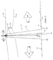
- FIGS 1 and 2 are somewhat schematic diagrams of, respectively, transmitters being first and second embodiments of the invention.
- a typical support tower 10 for an electricity transmission network includes several steel legs 12 each of which is approximately vertical. Various additional metal components are included to enhance the tower's strength (these have been omitted from the drawings in the interest of clarity). The whole tower thus forms an approximately vertical conductor.
- the tower 10 is supported on the ground on its legs 12. The legs 12 are not electrically isolated from the ground and the entire tower is therefore earthed at 16.
- Current carrying conductors 20 are supported by the tower 10.
- several side arms 22 project from the tower 10 laterally.
- One or more insulators 24 are carried on each arm, the current carrying conductors 20 being suspended from the insulator or insulators, as the case may be.
- the tower 10 also carries an earth conductor 26 which is electrically bonded to the metal components of the tower 10. Normally, the earth conductor 26 is carried at the top of the tower 10.
- the earth conductor 26 and the towers together form one system of interconnected electrical conductors, which is electrically isolated from the current carrying conductors 20.
- a transmitter unit 18 is provided at the tower 10.
- the transmitter unit 18 is electrically connected to the tower 10 to feed radiofrequency signals to the tower such that the tower serves as a transmitting antenna for the transmitter.
- Signals to be transmitted by the transmitter can be conveyed to it through a dedicated communication line 30.
- a dedicated communication line 30 is commonly installed at sub-stations within an EDN.
- signals to be transmitted may be conveyed to the transmitter unit 18 by an optical fibre link carried on the earth conductor 26.
- the tower 10 In order for the tower 10 to operate successfully as a transmitting antenna, it is preferably tuned to match the signal that it is to transmit. To achieve this it must first be realised that the earth conductor 26 forms a capacitor with respect to the ground 14. The effect of this is that the tower is capacitively top loaded: the earth conductor 26 therefore has a function equivalent to that of a capacity hat, which will be familiar to those skilled in antenna design, which serves to reduce the height of the antenna required to transmit a signal of a given wavelength. Thus, with suitable impedance matching, the top-loaded tower can operate as a ground wave transmitting antenna.
- a further consideration is that there should be a current node for the communication signals in the tower 10 where the legs 12 of the tower are supported on the ground 14. This obviates the need to insulate the tower from earth.
- FIG. 2 A second embodiment will now be described with reference to Figure 2.
- This embodiment is constructed on an EDN which comprises spaced towers 50 which support a plurality of conductors including an earth conductor 52.
- a transmitter unit 54 is located between two of the towers 50.
- An uplink conductor 56 extends from the transmitter unit 54 to the earth conductor 52.
- the uplink conductor 56 acts as a radiating element and the earth wire 42 serves as a capacitive hat for the uplink conductor 56.
- the towers 50 do not radiate significantly. It will be understood that the towers need not therefore be made of a conductive material; they can, for example, be wooden poles, such as are commonly used in electricity distribution systems in rural areas. However, this embodiment could equally be used in an electricity transmission network incorporating large metal towers.
Landscapes
- Cable Transmission Systems, Equalization Of Radio And Reduction Of Echo (AREA)
- Details Of Aerials (AREA)
- Support Of Aerials (AREA)
Applications Claiming Priority (2)
| Application Number | Priority Date | Filing Date | Title |
|---|---|---|---|
| GBGB9815410.7A GB9815410D0 (en) | 1998-07-15 | 1998-07-15 | Radio broadcasting system |
| GB9815410 | 1998-07-15 |
Publications (2)
| Publication Number | Publication Date |
|---|---|
| EP0980156A2 true EP0980156A2 (de) | 2000-02-16 |
| EP0980156A3 EP0980156A3 (de) | 2001-12-05 |
Family
ID=10835590
Family Applications (1)
| Application Number | Title | Priority Date | Filing Date |
|---|---|---|---|
| EP99305586A Withdrawn EP0980156A3 (de) | 1998-07-15 | 1999-07-14 | Vorrichtung für die Übertragung von Rundfunkprogrammen, mit einer Antennenvorrichtung die wenigstens teilweise aus dem oberirdischen Teil einer Elektrizitätsverteileinrichtung besteht |
Country Status (2)
| Country | Link |
|---|---|
| EP (1) | EP0980156A3 (de) |
| GB (2) | GB9815410D0 (de) |
Families Citing this family (2)
| Publication number | Priority date | Publication date | Assignee | Title |
|---|---|---|---|---|
| IES20000857A2 (en) * | 2000-10-25 | 2001-12-12 | Eircell 2000 Plc | Cellular base station antenna unit |
| GB2380322B (en) * | 2001-06-20 | 2004-07-21 | Esbi Engineering | Cellular telephone antenna and method of installation of the same |
Family Cites Families (5)
| Publication number | Priority date | Publication date | Assignee | Title |
|---|---|---|---|---|
| DE1303212B (de) * | 1961-09-27 | Siemens Ag | ||
| US3993989A (en) * | 1975-05-19 | 1976-11-23 | Trw Inc. | ELF communications system using HVDC transmission line as antenna |
| US4142178A (en) * | 1977-04-25 | 1979-02-27 | Westinghouse Electric Corp. | High voltage signal coupler for a distribution network power line carrier communication system |
| SE428338B (sv) * | 1981-11-16 | 1983-06-20 | Mobiltelefonservice Ab | Anordning for radiokommunikation i atminstone en riktning inom en storre byggnad eller liknande |
| US4724381A (en) * | 1986-02-03 | 1988-02-09 | Niagara Mohawk Power Corporation | RF antenna for transmission line sensor |
-
1998
- 1998-07-15 GB GBGB9815410.7A patent/GB9815410D0/en not_active Ceased
-
1999
- 1999-07-14 GB GB9916555A patent/GB2340310A/en not_active Withdrawn
- 1999-07-14 EP EP99305586A patent/EP0980156A3/de not_active Withdrawn
Also Published As
| Publication number | Publication date |
|---|---|
| GB9916555D0 (en) | 1999-09-15 |
| GB2340310A (en) | 2000-02-16 |
| GB9815410D0 (en) | 1998-09-16 |
| EP0980156A3 (de) | 2001-12-05 |
Similar Documents
| Publication | Publication Date | Title |
|---|---|---|
| US7791215B2 (en) | Intra-bundle power line carrier current system | |
| US9906303B2 (en) | Remote radio heads having wireless jumper connections and related equipment, systems and methods | |
| US4476576A (en) | VLF Communication system | |
| US6486846B1 (en) | E H antenna | |
| US6018324A (en) | Omni-directional dipole antenna with a self balancing feed arrangement | |
| CA2336613C (en) | Multi-frequency band antenna | |
| Belrose | Radiation characteristics of an electrically small MF broadcast antenna-by simulation | |
| JPS6367002A (ja) | 送電線センサー装置用の送信アンテナ装置及び送電線センサー装置 | |
| GB2368468A (en) | Antenna mounted on street lamp or telegraph pole | |
| US5999141A (en) | Enclosed dipole antenna and feeder system | |
| US3253279A (en) | Bandwidth monopole antenna having low ground losses due to a circumferential ground ring | |
| CA2462721C (en) | Antenna system utilizing elevated, resonant, radial wires | |
| US2767397A (en) | Antenna | |
| US2441086A (en) | Radio antenna | |
| GB2340310A (en) | Radio broadcasting system | |
| AU2005299526A1 (en) | Arrangement of inductive couplers for data communication | |
| EP1860725B1 (de) | Strahlenemittierendes kabel und darin enthaltenes strahlenemittierendes element | |
| US2140174A (en) | Antenna accessory | |
| KR20070084960A (ko) | 방사형 누설 동축 케이블 | |
| US6784848B2 (en) | Broad band slot style television broadcast antenna | |
| US11394126B1 (en) | Distributed monopole transmitter | |
| CA2885936C (en) | Operation of an antenna on a second, higher frequency | |
| US8774866B1 (en) | Electrically floating, near vertical incidence, skywave antenna | |
| US7109946B2 (en) | Hectometric wave transmission antenna | |
| CN121307486B (zh) | 一种多单元甚低频发信天线系统及其调谐方法 |
Legal Events
| Date | Code | Title | Description |
|---|---|---|---|
| PUAI | Public reference made under article 153(3) epc to a published international application that has entered the european phase |
Free format text: ORIGINAL CODE: 0009012 |
|
| AK | Designated contracting states |
Kind code of ref document: A2 Designated state(s): AT BE CH CY DE DK ES FI FR GB GR IE IT LI LU MC NL PT SE |
|
| AX | Request for extension of the european patent |
Free format text: AL PAYMENT 19990802;LT PAYMENT 19990802;LV PAYMENT 19990802;MK PAYMENT 19990802;RO PAYMENT 19990802;SI PAYMENT 19990802 |
|
| PUAL | Search report despatched |
Free format text: ORIGINAL CODE: 0009013 |
|
| AK | Designated contracting states |
Kind code of ref document: A3 Designated state(s): AT BE CH CY DE DK ES FI FR GB GR IE IT LI LU MC NL PT SE |
|
| AX | Request for extension of the european patent |
Free format text: AL PAYMENT 19990802;LT PAYMENT 19990802;LV PAYMENT 19990802;MK PAYMENT 19990802;RO PAYMENT 19990802;SI PAYMENT 19990802 |
|
| RIC1 | Information provided on ipc code assigned before grant |
Free format text: 7H 04H 1/00 A, 7H 01Q 1/00 B, 7H 01Q 1/46 B |
|
| STAA | Information on the status of an ep patent application or granted ep patent |
Free format text: STATUS: THE APPLICATION IS DEEMED TO BE WITHDRAWN |
|
| AKX | Designation fees paid |
Free format text: AT BE CH CY DE DK ES FI FR GB GR IE IT LI LU MC NL PT SE |
|
| AXX | Extension fees paid |
Free format text: AL PAYMENT 19990802;LT PAYMENT 19990802;LV PAYMENT 19990802;MK PAYMENT 19990802;RO PAYMENT 19990802;SI PAYMENT 19990802 |
|
| 18D | Application deemed to be withdrawn |
Effective date: 20020201 |