EP0980199B1 - Installation de porte, plus spécialement interphone - Google Patents
Installation de porte, plus spécialement interphone Download PDFInfo
- Publication number
- EP0980199B1 EP0980199B1 EP99113875A EP99113875A EP0980199B1 EP 0980199 B1 EP0980199 B1 EP 0980199B1 EP 99113875 A EP99113875 A EP 99113875A EP 99113875 A EP99113875 A EP 99113875A EP 0980199 B1 EP0980199 B1 EP 0980199B1
- Authority
- EP
- European Patent Office
- Prior art keywords
- module units
- plug
- module
- another
- intercom system
- Prior art date
- Legal status (The legal status is an assumption and is not a legal conclusion. Google has not performed a legal analysis and makes no representation as to the accuracy of the status listed.)
- Expired - Lifetime
Links
- 238000009434 installation Methods 0.000 title description 4
- 239000004020 conductor Substances 0.000 claims description 3
- 230000004308 accommodation Effects 0.000 claims 2
- 230000000295 complement effect Effects 0.000 abstract 1
- 230000005540 biological transmission Effects 0.000 description 2
- 230000002146 bilateral effect Effects 0.000 description 1
- 230000001419 dependent effect Effects 0.000 description 1
- 238000009429 electrical wiring Methods 0.000 description 1
Images

Classifications
-
- H—ELECTRICITY
- H04—ELECTRIC COMMUNICATION TECHNIQUE
- H04M—TELEPHONIC COMMUNICATION
- H04M1/00—Substation equipment, e.g. for use by subscribers
- H04M1/02—Constructional features of telephone sets
- H04M1/0291—Door telephones
Definitions
- the invention relates to a door intercom system having a door station, which has a receiving housing for module units which can be lined up in rows and columns, wherein the modular units are electrically connected to one another by means of connecting lines.
- Door systems, especially door intercoms of this type have been known for many years in different designs, which are constructed in a modular manner and record different modular units in the receiving housing row and / or column by row, in particular the FR-PS 2 122 912 , the DE-OS 31 08 056 and the DE 40 19 837 C2 demonstrate.
- module units are provided at the perpendicular to the rows and / or columns and each opposite outer sides with plug-in connections, which are electrically connected in parallel in the modular unit by means of multiple lines and in line and / or column direction aligned plug-in terminals of adjacent module units each designed as a plug connector and socket directly plugged into each other or are uniformly designed as sockets or power strips via additional connector strips or additional sockets are connected to each other.
- module units are provided with these plug connections and multiple lines, then they are already electrically connected to one another during installation in the receiving housing.
- the module units are connected in multiple through these connectors. If all module units are uniformly provided with sockets, which may preferably be installed flush in the outer sides of the module units, then additional connector strips are used for the two-sided connection of sockets for connecting adjacent module units.
- This type of connection has the advantage that the receiving housing can enclose the field of modular and / or column-by-row modular units with a small distance.
- modular units can also carry uniformly designed as plug-in connectors plug-in connections and to connect adjacent module units then additional sockets are used, which can accommodate both sides power strips.
- the module units each carry a plug strip and a socket at the respective opposite outer side pairs that the two pairs of plug connector and socket are electrically interconnected via a respective multi-line and that the two multiple lines are connected in parallel vein-individually ,
- the module units designed in this way can then be plugged together directly in rows and columns and at the same time electrically switch in multiple ways.
- the electrical wiring of the module unit is carried out according to an embodiment in a simple manner in that all as sockets and / or as power strips trained plug-in connections of the module unit mounted on a circuit board and are connected in parallel by means of printed conductor tracks vernindividuell.
- the module units have a square shape.
- the multiple lines are placed in the edge regions of two perpendicular abutting outer sides of the circuit board and electrically connected to each other in the intersection of their wires, then remains on the circuit board enough space for attachment and wiring required for the function of the module unit Components that can also be connected to the multiple lines.
- the printed circuit board is accommodated in the module unit, so that the wiring required for the multiple connection of the module units is part of the module units.
- the one multi-line on the top and the other multiple line are applied to the underside of the circuit board, so that at the intersection points, the individual wires of the multiple lines can be plated through in a simple manner.
- connection of the door system is carried out according to an embodiment, characterized in that housed in the receiving housing module units are electrically connected by a connector plug formed on one side as a connector strip or socket and a peripherally free socket or connector strip of a modular unit in rows and / or columns interconnected module units is attachable, and that the connector on the other side is provided with screw terminals for the wires of a connecting cable.
- module units in a grid arranged at any point module units can be easily replaced, provides an advantageous embodiment that when lined up in rows and columns module units in only one row or column module units are connected to each other via connectors that starting from this row or column the column or row by row subsequent module units are connected by means of plug-in connections with the multi-module units of this row or column and that the module units carry flush-mounted sockets on all sides, which are connected to each other with additional plugs.
- the module units can then be detached in columns or rows from the module row or module column, which is connected in series in the row or column.
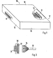
- a module unit 10 is shown in a square shape, wherein the mechanical elements for the installation of the module unit 10 are omitted in an unillustrated receiving housing, since they are for the present invention are not important and can be formed in a known manner.
- the modular unit 10 be provided with plug-in terminals 11 and 12 on at least two opposite outer sides, e.g. 16 and 17, is provided.
- the plug-in terminals 11 are formed in the embodiment shown as a power strip and the plug-in connections 12 as a socket, so that modular units 10 can be plugged together line by line.
- the connector strip and the socket are electrically connected in parallel via a multiple line 13.
- the plug-in connections 11 and 12 can be installed flush in the outer sides 16 and 17 of the module unit 10.
- the module unit 10 therefore forms a unit with the wiring.
- the module units 10 can be plugged into each other both in rows and columns and electrically switch multiple times.
- the module units 10 are first put together line by line or column by column and then the "module rows” or “module columns” are inserted into one another.
- the plug-in connections 11 and 12 of the module units 10 can also be formed uniformly as sockets and flush mounted in the outer sides 16 to 19 of the module unit 10.
- plug-in connectors are used both in the row and in the column direction, which are connectable with sockets on both sides.
- the receiving housing can then tightly enclose the grid of the modular units 10.
- Fig. 2 shows a circuit board 20 which can be inserted into the housing of the modular unit 10 and which is provided in the edge areas of two mutually perpendicular outer sides, e.g. 23 and 22, each carrying a multiple line 13.1 and 13.2.
- Each multiple line 13.1 and 13.2 is completed with a connector strip as a plug connection 11.1 or 11.2 and a socket as a plug connection 12.1 and 12.2, which are accessible via the outer sides 21 and 23 or 22 and 24.
- the modular units 10 can be assembled in rows and columns to any size "grid", the connectors can still support the mechanical support of the modular units 10 in a receiving housing.
- the plug-in connections 11.1, 11.2 and 12.1, 12.2 may be formed uniformly as sockets or power strips and used for the connection of adjacent module units 10 additional connector strips for two-sided connection with sockets or additional sockets for bilateral connection with power strips.
- the multiple lines 13.1 and 13.2 are preferably applied as printed conductors on the top and bottom of the circuit board 20.
- the multiple lines 13.1 and 13.2 are plated through at the crossing points of their wires and so connected in parallel.
- the connector 30 is formed on the one hand as a connector strip 31, which can be connected to a free at the periphery of the "grid” of modular units 10, designed as a socket plug-in connection 12.1 or 12.2.
- the connector 30 is provided with screw terminals 32 for the wires 34 of the connecting cable 33.
- the connector 30 may also be provided with a socket instead of the connector strip 31, which is connectable with a plug connector designed as a free plug-in connection 11.1 or 11.2.
- module units 10 In the grid arrangement of the module units, not all module units need to be switched in rows and columns. This would make it more difficult to replace individual module units from the grid. Rather, an embodiment is sufficient, which is characterized in that in rowed rows and columns module units 10 only in a row or column, the module units 10 are connected to each other via connectors, that starting from this row or column, the column or row by module subsequent module units 10 means Plug connections are connected to the multiply connected modular units 10 of this row or column and that the module units 10 carry flush-mounted sockets on all sides, which can be connected to each other with additional plugs.
- the module units can be solved column or line by column or line by row of the columns or rows in the row or column module column or module column without obstruction of adjacent columns or rows, as they are not connected to each other in the other rows or columns by connectors.
Landscapes
- Engineering & Computer Science (AREA)
- Signal Processing (AREA)
- Structure Of Telephone Exchanges (AREA)
- Interconnected Communication Systems, Intercoms, And Interphones (AREA)
- Sub-Exchange Stations And Push- Button Telephones (AREA)
Claims (8)
- Interphone comprenant une station de porte qui présente des unités modulaires (10) pouvant être agencées successivement en lignes et colonnes et un boîtier de réception pour les unités modulaires (10), les unités modulaires (10) étant connectées électriquement les unes aux autres au moyen de lignes de connexion (13 ; 13.1 ; 13.2), les unités modulaires (10) étant pourvues de connexions à fiches (11 et 12, respectivement 11.1 et 12.1, respectivement 11.2 et 12.2) au niveau des côtés extérieurs opposés (16 et 17 respectivement 18 et 19) perpendiculaires aux lignes et aux colonnes, les connexions à fiches étant montées dans l'unité modulaire en parallèle au moyen de lignes multiples (13 ; 13.1 ; 13.2), des connexions à fiches, orientées les unes vers les autres dans la direction des lignes et/ou des colonnes, d'unités modulaires adjacentes (10) étant réalisées à chaque fois sous forme de barrettes de connexion et de douilles de connexion et pouvant être enfichées directement les unes dans les autres ou bien étant réalisées sous forme unitaire en tant que douilles de connexion ou barrettes de connexion et pouvant être connectées les unes aux autres par le biais de barrettes de connexion supplémentaires ou de douilles de connexion supplémentaires,
caractérisé en ce que
les unités modulaires (10) portent une barrette de connexion et une douille de connexion respectives sur les paires de côtés extérieurs opposés (16 et 17, respectivement 18 et 19),
en ce que toutes les connexions à fiches (11 et 12 ; 11.1, 12.1, 11.2 et 12.2) réalisées sous forme de douilles de connexion et/ou de barrettes de connexion de l'unité modulaire (10) sont fixées sur une carte à circuits imprimés (20) et sont connectées les unes aux autres au moyen des lignes multiples (13.1 et 13.2) et en ce que les deux lignes multiples (13.1 et 13.2) sont montées sous forme de pistes conductrices imprimées sur la carte à circuits imprimés (20) et sont branchées en parallèle par fils individuels. - Interphone selon la revendication 1,
caractérisé en ce que
les unités modulaires (10) présentent des formes parallélépipédiques. - Interphone selon la revendication 1 ou 2,
caractérisé en ce que
les lignes multiples (13.1 et 13.2) sont posées dans la région de bord de deux côtés extérieurs (22 et 23) butant verticalement l'un contre l'autre de la carte à circuits imprimés (20) et sont connectées l'une à l'autre électriquement dans la région des intersections de leurs fils. - Interphone selon l'une quelconque des revendications 1 à 3,
caractérisé en ce que
la carte à circuits imprimés (20) est montée dans le boîtier de l'unité modulaire (10), et
en ce que les composants nécessaires pour le fonctionnement des unités modulaires (10) sont fixés sur la carte à circuits imprimés (20) et sont câblés avec les lignes multiples (13 ; 13.1 ; 13.2). - Interphone selon l'une quelconque des revendications 3 à 4,
caractérisé en ce que
l'une des lignes multiples (par exemple 13.1) est montée sur le côté supérieur et l'autre ligne multiple (par exemple 13.2) est montée sur le côté inférieur de la carte à circuits imprimés (20). - Interphone selon l'une quelconque des revendications 1 à 5,
caractérisé en ce que
les unités modulaires (10) montées dans le boîtier de réception peuvent être raccordées électriquement au moyen d'une fiche de connexion (30) qui est réalisée d'un côté sous forme de barrette de connexion (31) ou de douille de connexion, et qui peut être enfichée avec une douille de connexion ou une barrette de connexion libre du côté périphérique d'une unité modulaire des unités modulaires (10) connectées les unes aux autres en lignes et/ou colonnes, et
en ce que la fiche de connexion (30) est pourvue de l'autre côté de raccords vissés (32) pour les fils (34) d'un câble de raccordement (33). - Interphone selon l'une quelconque des revendications 1 à 8,
caractérisé en ce que
les barrettes de connexion et/ou les douilles de connexion sont incorporées en affleurement avec les côtés extérieurs (16, 17, 18, 19) dans les unités modulaires (10). - Interphone selon l'une quelconque des revendications 1 à 7,
caractérisé en ce que
parmi les unités modulaires (10) agencées successivement en lignes et colonnes, les unités modulaires (10) sont connectées les unes aux autres par le biais de connexions à fiches uniquement dans une ligne ou une colonne,
en ce qu'à partir de cette ligne ou de cette colonne, les unités modulaires (10) se raccordant en colonnes ou en lignes sont connectées au moyen de connexions à fiches aux unités modulaires (10) montées sous forme multiple de cette ligne ou colonne, et
en ce que les unités modulaires (10) portent de tous les côtés des douilles de connexion encastrées en affleurement qui peuvent être connectées les unes aux autres avec des connecteurs supplémentaires.
Applications Claiming Priority (2)
| Application Number | Priority Date | Filing Date | Title |
|---|---|---|---|
| DE19836479 | 1998-08-12 | ||
| DE19836479A DE19836479C5 (de) | 1998-08-12 | 1998-08-12 | Türanlage, insbesondere Türsprechanlage |
Publications (3)
| Publication Number | Publication Date |
|---|---|
| EP0980199A2 EP0980199A2 (fr) | 2000-02-16 |
| EP0980199A3 EP0980199A3 (fr) | 2000-10-18 |
| EP0980199B1 true EP0980199B1 (fr) | 2008-01-09 |
Family
ID=7877267
Family Applications (1)
| Application Number | Title | Priority Date | Filing Date |
|---|---|---|---|
| EP99113875A Expired - Lifetime EP0980199B1 (fr) | 1998-08-12 | 1999-07-16 | Installation de porte, plus spécialement interphone |
Country Status (3)
| Country | Link |
|---|---|
| EP (1) | EP0980199B1 (fr) |
| AT (1) | ATE383736T1 (fr) |
| DE (2) | DE19836479C5 (fr) |
Families Citing this family (1)
| Publication number | Priority date | Publication date | Assignee | Title |
|---|---|---|---|---|
| DE10045872C2 (de) * | 2000-09-14 | 2003-06-12 | Skytronic Gmbh Rf Comm & Techn | Elektrischer Baustein zur Weiterleitung von Signalen mindestens einer Empfangsantenne an mindestens einen Empfänger |
Citations (1)
| Publication number | Priority date | Publication date | Assignee | Title |
|---|---|---|---|---|
| DE4134044A1 (de) * | 1991-10-15 | 1993-04-22 | Grothe & Soehne Kg A | Tueranlage, insbesondere tuersprechanlage |
Family Cites Families (6)
| Publication number | Priority date | Publication date | Assignee | Title |
|---|---|---|---|---|
| CH545059A (it) * | 1971-01-23 | 1973-11-30 | Bassani Spa | Quadro per segnalazione elettrica, interfonia e simili |
| DE3108056C2 (de) * | 1981-03-04 | 1990-03-29 | S. Siedle & Söhne Telefon- und Telegrafenwerke GmbH, 7743 Furtwangen | Türanlage |
| DE4009190C1 (en) * | 1990-03-22 | 1991-09-19 | Ritto-Werk Loh Gmbh & Co Kg, 6342 Haiger, De | Door-installation for modular system - has arresting springs for receptacle for flat fixing frame e.g. for entry phone units |
| DE4019465A1 (de) * | 1990-04-03 | 1991-10-10 | Merten Gmbh & Co Kg Geb | Anschlusseinrichtung fuer die hausleittechnik |
| DE4019837A1 (de) * | 1990-06-21 | 1992-01-09 | Grothe & Soehne Kg A | Tueranlage, insbesondere tuersprechanlage |
| EP0505913B2 (fr) * | 1991-03-19 | 2001-11-07 | Bitron Video S.r.l. | Système d'assemblage du module d'appel externe pour un interphone audiovisuel pour immeubles. |
-
1998
- 1998-08-12 DE DE19836479A patent/DE19836479C5/de not_active Expired - Fee Related
-
1999
- 1999-07-16 AT AT99113875T patent/ATE383736T1/de not_active IP Right Cessation
- 1999-07-16 DE DE59914606T patent/DE59914606D1/de not_active Expired - Lifetime
- 1999-07-16 EP EP99113875A patent/EP0980199B1/fr not_active Expired - Lifetime
Patent Citations (1)
| Publication number | Priority date | Publication date | Assignee | Title |
|---|---|---|---|---|
| DE4134044A1 (de) * | 1991-10-15 | 1993-04-22 | Grothe & Soehne Kg A | Tueranlage, insbesondere tuersprechanlage |
Also Published As
| Publication number | Publication date |
|---|---|
| DE19836479C1 (de) | 2000-03-02 |
| DE59914606D1 (de) | 2008-02-21 |
| ATE383736T1 (de) | 2008-01-15 |
| EP0980199A3 (fr) | 2000-10-18 |
| EP0980199A2 (fr) | 2000-02-16 |
| DE19836479C5 (de) | 2006-11-09 |
Similar Documents
| Publication | Publication Date | Title |
|---|---|---|
| EP0712267B1 (fr) | Installation de commande modulaire avec connexion sur bus secteur intégré | |
| EP0709921B1 (fr) | Barrette d'interconnexion pour repartition transversale de puissance | |
| EP0364618B1 (fr) | Appareil de transmission de signal multiple | |
| EP0709932B1 (fr) | Installation de réglage avec bus, par example pour l'automation d'édifice | |
| EP0677986B1 (fr) | Elément d'un appareil d'automatisation | |
| EP1022934B1 (fr) | Tronçon de bus pour appareil électrique | |
| EP2351154B1 (fr) | Agencement de bornes en série avec raccordements transversaux et connecteurs d'essai | |
| EP0452658A1 (fr) | Unité de connexion pour installations domestiques | |
| EP3241261B1 (fr) | Dispositif de protection contre des surtensions pour la technique des informations et des télécommunications | |
| EP0584592B1 (fr) | Unité centrale | |
| CH629059A5 (de) | Mit anschlussorganen fuer anschlussdraehte versehene elektrische anschlussplatte. | |
| EP0709919B1 (fr) | Barrette d'interconnexion pour repartition transversale de puissance | |
| EP0180856A2 (fr) | Appareil électrique | |
| WO1997041715A1 (fr) | Peripherique modulaire extensible par modules et a structure autonome | |
| DE3910913A1 (de) | Pneumatische oder hydraulische ventileinheit | |
| EP0262325B1 (fr) | Dispositif pour distributeur | |
| DE19718920C2 (de) | Leitungssatz für ein Kraftfahrzeug | |
| DE3142182A1 (de) | Steckverbindersystem | |
| DE3336817A1 (de) | Stecksystem fuer elektrische installationen | |
| DE19816391C2 (de) | Türstation einer Türsprechanlage | |
| DE60105268T2 (de) | Paneelsystem für Kommunikationsklinken | |
| DE2340773A1 (de) | Uebergabesteckverbindung | |
| EP0980199A2 (fr) | Installation de porte, plus spécialement interphone | |
| DE29825108U1 (de) | Türanlage, insbesondere Türsprechanlage | |
| EP1365478B1 (fr) | Module aligné et module adaptateur |
Legal Events
| Date | Code | Title | Description |
|---|---|---|---|
| PUAI | Public reference made under article 153(3) epc to a published international application that has entered the european phase |
Free format text: ORIGINAL CODE: 0009012 |
|
| AK | Designated contracting states |
Kind code of ref document: A2 Designated state(s): AT BE CH CY DE DK ES FI FR GB GR IE IT LI LU MC NL PT SE |
|
| AX | Request for extension of the european patent |
Free format text: AL;LT;LV;MK;RO;SI |
|
| PUAL | Search report despatched |
Free format text: ORIGINAL CODE: 0009013 |
|
| AK | Designated contracting states |
Kind code of ref document: A3 Designated state(s): AT BE CH CY DE DK ES FI FR GB GR IE IT LI LU MC NL PT SE |
|
| AX | Request for extension of the european patent |
Free format text: AL;LT;LV;MK;RO;SI |
|
| 17P | Request for examination filed |
Effective date: 20010418 |
|
| AKX | Designation fees paid |
Free format text: AT BE CH CY DE DK ES FI FR GB GR IE IT LI LU MC NL PT SE |
|
| 17Q | First examination report despatched |
Effective date: 20060228 |
|
| RTI1 | Title (correction) |
Free format text: DOOR INSTALLATION, ESPECIALLY DOOR TELEPHONE |
|
| GRAP | Despatch of communication of intention to grant a patent |
Free format text: ORIGINAL CODE: EPIDOSNIGR1 |
|
| GRAS | Grant fee paid |
Free format text: ORIGINAL CODE: EPIDOSNIGR3 |
|
| GRAA | (expected) grant |
Free format text: ORIGINAL CODE: 0009210 |
|
| AK | Designated contracting states |
Kind code of ref document: B1 Designated state(s): AT BE CH CY DE DK ES FI FR GB GR IE IT LI LU MC NL PT SE |
|
| REG | Reference to a national code |
Ref country code: GB Ref legal event code: FG4D Free format text: NOT ENGLISH |
|
| REG | Reference to a national code |
Ref country code: CH Ref legal event code: EP |
|
| REG | Reference to a national code |
Ref country code: IE Ref legal event code: FG4D Free format text: LANGUAGE OF EP DOCUMENT: GERMAN |
|
| REF | Corresponds to: |
Ref document number: 59914606 Country of ref document: DE Date of ref document: 20080221 Kind code of ref document: P |
|
| PG25 | Lapsed in a contracting state [announced via postgrant information from national office to epo] |
Ref country code: NL Free format text: LAPSE BECAUSE OF FAILURE TO SUBMIT A TRANSLATION OF THE DESCRIPTION OR TO PAY THE FEE WITHIN THE PRESCRIBED TIME-LIMIT Effective date: 20080109 |
|
| NLV1 | Nl: lapsed or annulled due to failure to fulfill the requirements of art. 29p and 29m of the patents act | ||
| PG25 | Lapsed in a contracting state [announced via postgrant information from national office to epo] |
Ref country code: FI Free format text: LAPSE BECAUSE OF FAILURE TO SUBMIT A TRANSLATION OF THE DESCRIPTION OR TO PAY THE FEE WITHIN THE PRESCRIBED TIME-LIMIT Effective date: 20080109 Ref country code: ES Free format text: LAPSE BECAUSE OF FAILURE TO SUBMIT A TRANSLATION OF THE DESCRIPTION OR TO PAY THE FEE WITHIN THE PRESCRIBED TIME-LIMIT Effective date: 20080420 |
|
| GBV | Gb: ep patent (uk) treated as always having been void in accordance with gb section 77(7)/1977 [no translation filed] | ||
| PG25 | Lapsed in a contracting state [announced via postgrant information from national office to epo] |
Ref country code: PT Free format text: LAPSE BECAUSE OF FAILURE TO SUBMIT A TRANSLATION OF THE DESCRIPTION OR TO PAY THE FEE WITHIN THE PRESCRIBED TIME-LIMIT Effective date: 20080609 |
|
| REG | Reference to a national code |
Ref country code: IE Ref legal event code: FD4D |
|
| EN | Fr: translation not filed | ||
| PG25 | Lapsed in a contracting state [announced via postgrant information from national office to epo] |
Ref country code: SE Free format text: LAPSE BECAUSE OF FAILURE TO SUBMIT A TRANSLATION OF THE DESCRIPTION OR TO PAY THE FEE WITHIN THE PRESCRIBED TIME-LIMIT Effective date: 20080409 Ref country code: IE Free format text: LAPSE BECAUSE OF FAILURE TO SUBMIT A TRANSLATION OF THE DESCRIPTION OR TO PAY THE FEE WITHIN THE PRESCRIBED TIME-LIMIT Effective date: 20080109 Ref country code: DK Free format text: LAPSE BECAUSE OF FAILURE TO SUBMIT A TRANSLATION OF THE DESCRIPTION OR TO PAY THE FEE WITHIN THE PRESCRIBED TIME-LIMIT Effective date: 20080109 |
|
| PLBE | No opposition filed within time limit |
Free format text: ORIGINAL CODE: 0009261 |
|
| STAA | Information on the status of an ep patent application or granted ep patent |
Free format text: STATUS: NO OPPOSITION FILED WITHIN TIME LIMIT |
|
| 26N | No opposition filed |
Effective date: 20081010 |
|
| PG25 | Lapsed in a contracting state [announced via postgrant information from national office to epo] |
Ref country code: GB Free format text: LAPSE BECAUSE OF FAILURE TO SUBMIT A TRANSLATION OF THE DESCRIPTION OR TO PAY THE FEE WITHIN THE PRESCRIBED TIME-LIMIT Effective date: 20080109 |
|
| REG | Reference to a national code |
Ref country code: CH Ref legal event code: PL |
|
| PG25 | Lapsed in a contracting state [announced via postgrant information from national office to epo] |
Ref country code: MC Free format text: LAPSE BECAUSE OF NON-PAYMENT OF DUE FEES Effective date: 20080731 |
|
| PG25 | Lapsed in a contracting state [announced via postgrant information from national office to epo] |
Ref country code: FR Free format text: LAPSE BECAUSE OF FAILURE TO SUBMIT A TRANSLATION OF THE DESCRIPTION OR TO PAY THE FEE WITHIN THE PRESCRIBED TIME-LIMIT Effective date: 20081031 |
|
| PG25 | Lapsed in a contracting state [announced via postgrant information from national office to epo] |
Ref country code: LI Free format text: LAPSE BECAUSE OF NON-PAYMENT OF DUE FEES Effective date: 20080731 Ref country code: CH Free format text: LAPSE BECAUSE OF NON-PAYMENT OF DUE FEES Effective date: 20080731 |
|
| PG25 | Lapsed in a contracting state [announced via postgrant information from national office to epo] |
Ref country code: CY Free format text: LAPSE BECAUSE OF FAILURE TO SUBMIT A TRANSLATION OF THE DESCRIPTION OR TO PAY THE FEE WITHIN THE PRESCRIBED TIME-LIMIT Effective date: 20080109 |
|
| PG25 | Lapsed in a contracting state [announced via postgrant information from national office to epo] |
Ref country code: IT Free format text: LAPSE BECAUSE OF FAILURE TO SUBMIT A TRANSLATION OF THE DESCRIPTION OR TO PAY THE FEE WITHIN THE PRESCRIBED TIME-LIMIT Effective date: 20080109 |
|
| PG25 | Lapsed in a contracting state [announced via postgrant information from national office to epo] |
Ref country code: AT Free format text: LAPSE BECAUSE OF NON-PAYMENT OF DUE FEES Effective date: 20080716 |
|
| PG25 | Lapsed in a contracting state [announced via postgrant information from national office to epo] |
Ref country code: LU Free format text: LAPSE BECAUSE OF NON-PAYMENT OF DUE FEES Effective date: 20080716 |
|
| PG25 | Lapsed in a contracting state [announced via postgrant information from national office to epo] |
Ref country code: BE Free format text: LAPSE BECAUSE OF NON-PAYMENT OF DUE FEES Effective date: 20080731 |
|
| PG25 | Lapsed in a contracting state [announced via postgrant information from national office to epo] |
Ref country code: GR Free format text: LAPSE BECAUSE OF FAILURE TO SUBMIT A TRANSLATION OF THE DESCRIPTION OR TO PAY THE FEE WITHIN THE PRESCRIBED TIME-LIMIT Effective date: 20080410 |
|
| REG | Reference to a national code |
Ref country code: DE Ref legal event code: R082 Ref document number: 59914606 Country of ref document: DE Representative=s name: HERRMANN, JOCHEN, DIPL.-ING., DE |
|
| PGFP | Annual fee paid to national office [announced via postgrant information from national office to epo] |
Ref country code: DE Payment date: 20170724 Year of fee payment: 19 |
|
| REG | Reference to a national code |
Ref country code: DE Ref legal event code: R119 Ref document number: 59914606 Country of ref document: DE |
|
| PG25 | Lapsed in a contracting state [announced via postgrant information from national office to epo] |
Ref country code: DE Free format text: LAPSE BECAUSE OF NON-PAYMENT OF DUE FEES Effective date: 20190201 |