EP0980265B1 - Methode zur kalt-sterilisation von öfen des tunnel-typs im pharmazeutischen bereich und öfen zur anwendung dieser methode - Google Patents
Methode zur kalt-sterilisation von öfen des tunnel-typs im pharmazeutischen bereich und öfen zur anwendung dieser methode Download PDFInfo
- Publication number
- EP0980265B1 EP0980265B1 EP98912680A EP98912680A EP0980265B1 EP 0980265 B1 EP0980265 B1 EP 0980265B1 EP 98912680 A EP98912680 A EP 98912680A EP 98912680 A EP98912680 A EP 98912680A EP 0980265 B1 EP0980265 B1 EP 0980265B1
- Authority
- EP
- European Patent Office
- Prior art keywords
- chamber
- oven
- sterilisation
- input
- duct
- Prior art date
- Legal status (The legal status is an assumption and is not a legal conclusion. Google has not performed a legal analysis and makes no representation as to the accuracy of the status listed.)
- Expired - Lifetime
Links
Images
Classifications
-
- A—HUMAN NECESSITIES
- A61—MEDICAL OR VETERINARY SCIENCE; HYGIENE
- A61L—METHODS OR APPARATUS FOR STERILISING MATERIALS OR OBJECTS IN GENERAL; DISINFECTION, STERILISATION OR DEODORISATION OF AIR; CHEMICAL ASPECTS OF BANDAGES, DRESSINGS, ABSORBENT PADS OR SURGICAL ARTICLES; MATERIALS FOR BANDAGES, DRESSINGS, ABSORBENT PADS OR SURGICAL ARTICLES
- A61L2/00—Disinfection or sterilisation of materials or objects, in general; Accessories therefor
- A61L2/16—Disinfection or sterilisation of materials or objects, in general; Accessories therefor using chemical substances
- A61L2/20—Gaseous substances, e.g. vapours
- A61L2/208—Hydrogen peroxide
-
- A—HUMAN NECESSITIES
- A61—MEDICAL OR VETERINARY SCIENCE; HYGIENE
- A61L—METHODS OR APPARATUS FOR STERILISING MATERIALS OR OBJECTS IN GENERAL; DISINFECTION, STERILISATION OR DEODORISATION OF AIR; CHEMICAL ASPECTS OF BANDAGES, DRESSINGS, ABSORBENT PADS OR SURGICAL ARTICLES; MATERIALS FOR BANDAGES, DRESSINGS, ABSORBENT PADS OR SURGICAL ARTICLES
- A61L2/00—Disinfection or sterilisation of materials or objects, in general; Accessories therefor
- A61L2/24—Apparatus using programmed or automatic operation
-
- A—HUMAN NECESSITIES
- A61—MEDICAL OR VETERINARY SCIENCE; HYGIENE
- A61L—METHODS OR APPARATUS FOR STERILISING MATERIALS OR OBJECTS IN GENERAL; DISINFECTION, STERILISATION OR DEODORISATION OF AIR; CHEMICAL ASPECTS OF BANDAGES, DRESSINGS, ABSORBENT PADS OR SURGICAL ARTICLES; MATERIALS FOR BANDAGES, DRESSINGS, ABSORBENT PADS OR SURGICAL ARTICLES
- A61L2103/00—Materials or objects being the target of disinfection or sterilisation
- A61L2103/23—Containers other than laboratory or medical, e.g. bottles or mail
Definitions
- the present invention relates to the technical field concerning the sterilisation of apparatuses or bottles for pharmaceutical use.
- the present invention relates to a method for sterilising the inside of a bottles sterilisation oven, and to an oven which carries out said method.
- the bottles sterilisation is usually carried out at high temperatures, inside a special sterilisation oven, which is configured as a "tunnel”, and which is stepless operated, for productivity purposes.
- the known sterilisation tunnel-type ovens normally comprise three cascade-connected and intercommunicating sections: an input chamber, a sterilisation chamber, also called hot chamber, and a cooling chamber for the sterilised bottles.
- the three above sections are crossed by a tape conveyor, that forwards the aforesaid bottles in sequence through all the sections.
- the input chamber has an input door, through which the bottles, coming from a washing station, are fed to the oven.
- the cooling chamber is provided with an output door for communicating with a sterile room, wherein bottles are filled with a drug and then sealed.
- the hot chamber is provided with suitable heaters, operable to heat the said chamber to a given temperature, which is high enough to sterilise all the bottles continuously passing therein.
- Bottles stay in the cooling chamber until their temperature attains a value approaching that of the subsequent sterile room.
- Said chamber is suitably provided with working fluid type heat exchangers, which help in lowering the air temperature inside the chamber, and consequently in lowering the bottles temperature.
- H.E.P.A filters of suitable retention characteristic features. They are kept in a slight plenum condition, in order to avoid any non-filtered air, which is therefore contaminated by particles and microorganisms, to flow into the oven.
- Some ovens provided with periodical sterilisation procedures for the cooling chamber are known, particularly by heating it to a temperature similar to those reached in the hot chamber, in order to kill all the pathogenic agents. This solution is extremely expensive and difficult to carry out and to sell. In fact, because of the cooling chamber size, high power heating assemblies must be provided; all the power lines and apparatuses that carry the power to the oven must be sized accordingly, and then practically doubled with respect to a conventional sterilisation oven.
- a further object of the present invention is to propose a such method which doesn't significantly affect oven production costs or its power consumption.
- a further object is to propose a sterilisation oven which is totally cold sterilisable, accordingly to the aforesaid method.
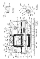
- numeral 1 indicates a sterilisation, tunnel-type oven, for the continuous hot sterilisation of bottles for pharmaceutical products.
- Said oven 1 substantially comprises a supporting frame 100, of approximately parallelepipedal shape. Inside the frame 100 an input chamber 3, a hot sterilisation chamber 4 and a cooling chamber 5 are successively arranged. These three chambers communicate one each other, by means of a first passage 134, between the input chamber 3 and the sterilisation chamber 4, and a second passage 145, between this latter and the cooling chamber 5.
- the input chamber 3 and cooling chamber 5 are also respectively provided with an input opening 31 and with an output opening 51, aligned with the passages 134,145.
- the input opening 31 receives the bottles coming from a previous washing apparatus, while the output opening 51 is connected in a know way to a sterile room, or to an insulating environment, wherein the sterilised bottles are filled with the corresponding pharmaceutical product, and then sealed.
- Chambers 3,4,5 are moreover crossed by a continuous tape conveyor 6, which is driven to a direction W at a given speed, generally variable according to known sequences.
- the tape conveyor 6 carries the above cited bottles on its upper branch 6a, during the normal oven operating procedures, from the input opening 31 to the output opening 51.
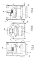
- the input chamber 3 has a first ventilation assembly 36, provided with a flow conveyor 36a and with a corresponding H.E.P.A. filter, and fit to generate a laminar flow of sterile air in the said chamber 3, according to known techniques (see also figure 3).
- the first ventilation assembly 36 is connected to the external environment by means of a first input duct 33, provided with a flow regulating valve 33a.
- An air output duct 34 is also provided at the upper end of the input chamber 3, and has an output flow regulating valve 34a and a discharge fan 34b. Said valve 34a and fan 34b are operated in a phase relationship with the first ventilation assembly 36.
- a first forced input duct 35 of a cold sterilisation fluid joins the first input duct 33 just downstream of the flow regulating valve 33a with respect to the air input flow, which is indicated with the V arrow in figure 1.
- Said duct 35 is provided with a first flow regulating valve 35a, driven according to pre-defined periodic sequences, in order to allow the input chamber to be cold sterilised.
- the first forced input duct 35 is connected to a source of that sterilisation fluid, not shown.
- a source of that sterilisation fluid preferably consists of a suitably measured mixture of hydrogen peroxide and air, whose temperature and humidity is suitably controlled.
- the mixture is provided by means of a known supply device, a rotating vane centrifugal pump.
- recycling or evacuating means 37 for the hydrogen peroxide is provided, fit to allow the same to be drained away from the oven 1, or its recycling and re-routing toward the supply device.
- the recycling or evacuating means consists of a duct, extending from the air output duct 34, just upstream of the flow regulating valve 34a and provided with its own flow regulating valve 37a, operated in a phase relationship with the same valve 34a.
- the duct 37 is connected to known recycling means for recycling the hydrogen peroxide or, optionally, to known exhausting means, both not shown.
- the hot sterilisation chamber 4 is provided in turn with a second ventilation assembly 46, provided with its own flow conveyor 46a and with a corresponding H.E.P.A. filter, and fit to generate a laminar flow of sterile air (see also figure 5).
- the second ventilation assembly 46 is connected to the external environment by means of a second input duct 43, which is also provided with its flow regulating valve 43a.
- a second forced input duct 45 of hydrogen peroxide joins the second input duct 43, downstream of the flow regulating valve 43a.
- Said duct is provided with a second flow regulating valve 45a, operable according to pre-defined periodic sequences, in a phase relationship with the operation of the first flow regulating valve 35a.
- a suitably thick layer of insulating material 140 is externally wrapped all around the hot sterilisation chamber 4, for thermically insulating the same, as well as possible, from the input chamber 3, the cooling chamber 5 and the external environment.
- first and second control joints 141,142 are sealingly provided (see detail in figure 2), fit to define the perimeter of said passages, to keep them airtight and to allow at the same time the sterilisation chamber 4 to expand and to contract according to its thermal variations.
- each of said control joints for instance the second control joint 142, consists of a corrugated plate 143 of elastic metal, which is fixed at its ends to the sterilisation chamber 4 and cooling chamber 5 walls by means of a continuous welding.
- a third ventilation assembly 56 is arranged in the-upper side of the cooling chamber 5, provided with its own flow conveyor 56a with a corresponding H.E.P.A. filter, and fit to generate a laminar flow of sterile air inside the same chamber 5 (see also figure 6).
- the third ventilation assembly 56 provides a closed loop air circulation, since it draws air from the inside of the same cooling chamber 5, in order to improve the air flow.
- a third forced input duct 55 of hydrogen peroxide is arranged at the upper end of the cooling chamber 5. This is provided with a third flow regulating valve 55a, which is operated, according to pre-defined periodic sequences, in a phase relationship with the operation of the first regulating valve 35a and of the second regulating valve 45a, in order to allow the cooling chamber 5 to be cold sterilised.
- the third forced input duct 55 is also connected to the aforesaid source of hydrogen peroxide.
- the cooling chamber 5 has a pair of heat exchangers 57, respectively a first one 57a and a second one 57b, fit to drain the heat released by the cooling down bottles. They are arranged in the middle portion of the cooling chamber 5, where the laminar flow direction is reversed.
- the whole oven 1 is hermetically sealed. More particularly, all the frame 100 junctions are made with continuous weldings, and the same frame 100 is provided with side panels 7 for covering the input chamber 3, the hot sterilisation chamber 4 and the cooling chamber 5. (figures 3,5,6).
- Each one of the above panels 7 has, all around the rim 7b of its inner wall 7a (see figure 4), an air tight closing means 70 comprising a gasket 71 which, when the panel is its operating position, interposes between the inner wall 7a of the same panel 7 and an outer face 101 of the frame 100.
- the gasket 71 is made of a shaped plate 73, which is fixed to the rim 7b and which extends all around its boundary, and of a pair of airtight curbs 74a,74b, fixed in turn to the shaped plate 73 and respectively parallel.
- the plate 73 and the curbs 74a,74b define, together with the outer face 101 of the frame 100, an airtight compartment 75.
- a suction duct 76 is fixed on the inner face 103 of the frame 100, exactly following the path of the airtight compartment 75.
- the suction duct 76 is connected to known suction means, which periodically bring said duct to a pressure lower than the atmospheric pressure.
- a plurality of through holes 77 is made in the frame 100, in order to establish a communication between the suction duct 76 and the airtight compartment 75.
- the input opening 31 and the output opening 51 are provided with airtight doors 38,58, connected to respective operating means 39,59, which are preferably automatically operated.
- a sterilisation sequence is periodically performed for the oven 1, and particularly for the input chamber 3 and the cooling chamber 5. These sequences are interlaced with the oven 1 normal operation periods.
- the sterilisation chamber 4 is intrinsically sterile.
- Each cold sterilisation sequence happens after the oven 1 normal operation has stopped, and the sterilisation chamber 4 has reached a temperature as low as about 40° Centigrade.
- the following operating phases are then carried out:
- a further over-pressurized ventilation phase can be provided for the oven 1, which is carried out by opening the flow regulating valves 33a,43a,34a of the input ducts 33,43 and output duct 34, and simultaneously activating the ventilation assemblies 36,46,56 and the discharge fan 34b.
- Sterilisation sequences like that described above can be performed either with a given frequence, or after the oven 1 has been opened for maintenance purposes.
- the method and oven of the present invention give a first advantage in that they allow, not only the cooling chamber 5 to be perfectly sterilised, thus avoiding the sterilised, cooling down bottles, from being contaminated by micro-organisms or any other contaminating agent, which would be otherwise present on the inner surfaces of the same cooling chamber 5, but also in that even the input chamber 3 and the hot sterilisation chamber 4, thus the whole oven 1, are perfectly sterilised.
- a further given advantage is that, for obtaining said sterilisation, there is no significant improvement in power consumption, and then of maximum required power supply.
- the oven 1 can be operated, during its normal operating life, at an over-pressure regime, not only with respect to the external environment, but also with respect to the sterile room and to the insulating environment. This allows the oven 1 operating settings and maintenance can be made independently from those of the same sterile room.
- the oven 1 can be advantageously placed even in a non-clean environment, since it is completely insulated from the external environment.
Landscapes
- Health & Medical Sciences (AREA)
- Veterinary Medicine (AREA)
- Life Sciences & Earth Sciences (AREA)
- Animal Behavior & Ethology (AREA)
- General Health & Medical Sciences (AREA)
- Public Health (AREA)
- Epidemiology (AREA)
- Chemical & Material Sciences (AREA)
- Chemical Kinetics & Catalysis (AREA)
- General Chemical & Material Sciences (AREA)
- Apparatus For Disinfection Or Sterilisation (AREA)
- Food Preservation Except Freezing, Refrigeration, And Drying (AREA)
- Medicinal Preparation (AREA)
Claims (16)
- Verfahren zur Kaltsterilisation eines tunnelartigen Ofens für pharmazeutische Zwecke, der mit mindestens einer Eingangskammer (3) ausgestattet ist, die dafür ausgebildet ist, um eine Mehrzahl von Flaschen aufzunehmen, die durch eine Eingangsöffnung (31) hindurch gefördert werden und zu sterilisieren sind, wobei ebenfalls mindestens eine Sterilisationskammer (4) zur Durchführung einer Heißsterilisation der Flaschen verwendet ist, die der Eingangskammer (3) nachfolgend angeordnet ist und die mit dieser in Verbindung steht, sowie bei der mindestens eine Kühlkammer (5) verwendet ist, die der Heißsterilisationskammer (4) nachfolgend angeordnet ist und mit dieser in Verbindung steht und die dafür ausgebildet ist, die sterilisierten und herunterzukühlenden Flaschen aufzunehmen und die mit mindestens einer Auslaßöffnung (51) zu versehen ist, sowie bei der Fördermittel (6) verwendet sind, um die Flaschen von der Eingangskammer (3) durch die Sterilisationskammer (4) hindurch zur Kühlkammer (5) zu fördern, wobei der Ofen (1) ebenfalls mit einer Mehrzahl von Eingangskanälen (33,43) versehen ist, um externe Luft in den Ofen (1) einzuleiten und wobei mindestens ein Eingangskanal (34) zur Ableitung der Luft in die externe Umgebung vorgesehen ist, wobei das Verfahren dadurch gekennzeichnet ist, daß die folgenden Verfahrensschritte periodisch durchgeführt werden:Luftdichtes Verschließen der Eingangsöffnung (31) und der Ausgangsöffnung (51) und der Eingangskanäle (31,43) und des Ausgangskanals (34);Öffnung von zusätzlichen Eingangsmitteln (35,45,55), um eine Mischung von Luft und eines Sterilisationsfluids mindestens in die Kühlkammer (5) einzuleiten;Bereitstellung einer vorbestimmten Menge der Mischung an Sterilisationsfluid und Luft, bis ein vorgegebener statischer Druck erreicht ist;Öffnung mindestens eines Ausgangskanals (37) für das Sterilisationsfluid;Beendigung der Zuführung des Sterilisationsfluids und Versorgung des Ofens (1) mit Luft kontrollierter Feuchtigkeit derart, daß der Anteil des Sterilisationsfluids innerhalb des Ofens (1) unter einen vorgegebenen wert abgesenkt ist;Schließen der zusätzlichen Eingangsmittel (35,45,55) und des Ausgangskanal (37) und erneutes öffnen der Eingangsöffnung (31) und der Ausgangsöffnung (51).
- Vorrichtung nach Anspruch 1, dadurch gekennzeichnet, daß das Sterilisationsfluid von drei zusätzlichen Eingangskanälen für das Sterilisationsfluid bereitgestellt wird, nämlich einem ersten Kanal (35), einem zweiten Kanal (45) und einem dritten Kanal (55), die jeweils in der Eingangskammer (3), der Heißsterilisationskammer (4) und der Kühlkammer (5) angeordnet sind.
- Verfahren nach Anspruch 1 oder 2, dadurch gekennzeichnet, daß vor einer Öffnungsphase der zusätzlichen Eingangskanäle (35,45,55) der Ofen (1) einer Lüftung mit Überdruck ausgesetzt wird, die durch die Eingangskanäle (33,43) und den Ausgangskanal (34) hindurch einwirkt.
- Verfahren nach Anspruch 1, dadurch gekennzeichnet, daß gleichzeitig mit der zuführungsphase für das Sterilisationsfluid erste Lüftungsmittel (36), zweite Lüftungsmittel (46) und dritte Lüftungsmittel (56) jeweils in der Eingangskammer (3), der Sterilisationskammer (4) und der Kühlkammer (5) für einer vorgegebene Zeitdauer betrieben werden.
- Verfahren nach einem der vorangegangenen Ansprüche, dadurch gekennzeichnet, daß als Sterilisationsfluid Hydrogenperoxid verwendet wird.
- Verfahren nach Anspruch 5, dadurch gekennzeichnet, daß das Hydrogenperoxid dampfförmig zugeführt wird.
- Tunnelartiger Ofen für pharmazeutische Anwendungen, der mit mindestens einer Eingangskammer ausgestattet ist, die zur Aufnahme einer Mehrzahl von Flaschen ausgebildet ist, die nach einem Einsetzen durch eine Eingangsöffnung (31) hindurch zu sterilisieren sind, mit mindestens einer Heißsterilisationskammer (4) für die Behälter, die im Anschluß an die Eingangskammer (3) angeordnet ist und mit dieser in Verbindung steht, mit mindestens einer Kühlkammer (5), die auf die Sterilisationskammer (4) folgend angeordnet ist und mit dieser in Verbindung steht und die dafür ausgebildet ist, die sterilisierten und abzukühlenden Flaschen aufzunehmen und bei der ebenfalls mindestens eine Ausgangsöffnung (51) vorgesehen ist, der Ofen (1) ist darüber hinaus mit Fördermitteln (6) ausgestattet, um die Flaschen ausgehend von der Eingangskammer (3) durch die Sterilisationskammer (4) und die Kühlkammer (5) hindurchzufördern, mit ersten Belüftungsmitteln (36), mit zweiten Belüftungsmitteln (46) und mit dritten Belüftungsmitteln (56), um jeweils eine Belüftung der Eingangskammer (3), der Heißsterilisationskammer (4) und der Kühlkammer (5) durchzuführen und die ebenfalls mit einer Mehrzahl von externen Luftzuführkanälen (33,43) ausgestattet ist und die mindestens einen Ausgangskanal (34) aufweist, um Luft in eine externe Umgebung abzuleiten, der Ofen (1) ist dadurch charakterisiert, das er die weiteren Merkmale aufweist:Türen (38,58) zum luftdichten verschließen der Eingangsöffnung (31) und der Ausgangsöffnung (51) ;luftdichte Verschlußmittel (70) von Verkleidungen (7) zur Bedeckung der Eingangskammer (3), der Heißsterilisationskammer (4) und der Kühlkammer (5);zusätzliche Eingangsmittel (35,45,55) für ein Kaltsterilisationsfluid, die dafür ausgebildet sind, das Sterilisationsfluid in den Ofen (1) einzuleiten;Recycling- oder Ableitungsmittel (37) für das Sterilisationsfluid, um das Sterilisationsfluid aus dem Ofen (1) heraus abzuleiten, bis ein Anteil des Sterilisationsfluids innerhalb des Ofens (1) unterhalb einen vorgegebenen Wert abgesenkt ist.
- Ofen nach Anspruch 7, dadurch gekennzeichnet, daß die zusätzlichen Eingangsmittel einen ersten Kanal (35), einen zweiten Kanal (45) und einen dritten Kanal (55) aufweisen, die jeweils mit Ventilen (35a,45a,55a) zur Durchflußregulierung ausgestattet sind und die mit einer Versorgungseinrichtung für ein Sterilisationsfluid verbunden sind.
- Ofen nach Anspruch 8, dadurch gekennzeichnet, daß der erste Kanal (35), der zweite Kanal (45) und der dritte Kanal (55) jeweils in der Eingangskammer (3), der Heißsterilisationskammer (4) und der Kühlkammer (5) angeordnet sind.
- ofen nach Anspruch 7, dadurch gekennzeichnet, daß die Recycling- oder Ableitungsmittel (37) mindestens einen Recycling- oder Ableitungskanal autweisen, der mit einem Ventil (37a) zur Realisierung eines Ausgangsflusses ausgestattet ist.
- Ofen nach Anspruch 10, dadurch gekennzeichnet, daß der Recycling- oder Ableitungskanal (37) in der Eingangskammer (3) angeordnet ist.
- ofen nach Anspruch 7, dadurch gekennzeichnet, daß die luftdichten verschlußmittel (70) für jede der bedeckenden Verkleidungen (7) mindestens eine Dichtung (71) bereitstellt, die mindestens eine Dichtung (71), die zwischen einer äußeren Fläche (101) eines Rahmens (100) des Ofens (1) und einer inneren Fläche (7a) der Verkleidung (7) angeordnet ist, nahe des Randes (7b) der letzteren und entlang deren Begrenzung angeordnet ist, die Dichtung (71) definiert in Zusammenwirkung mit der äußeren Fläche (101) mindestens einen luftdichten Bereich (75), der dafür ausgebildet ist, um den Ofen (1) von einer externen Umgebung zu isolieren; mindestens einen unterdruckkanal (76), der relativ zur inneren Fläche (103) des Rahmens befestigt ist und exakt dem Verlauf des luftdichten Bereichs (75) folgt, eine Mehrzahl von Durchgangslöchern (77) sind im Bereich des Rahmens (100) angeordnet, um eine Verbindung zwischen dem Unterdruckkanal (76) und dem luftdichten Bereich (75) bereitzustellen.
- Ofen nach Anspruch 12, dadurch gekennzeichnet, daß die Dichtung (71) mindestens eine gestaltete Platte (73) aufweist, die relativ zum Rand (7b) befestigt ist und die sich entlang dessen Begrenzung erstreckt und die mindestens ein Paar von parallelen luftdichten Begrenzungselementen (74a,74b) aufweist, die an der gestalteten Platte (73) befestigt sind.
- Ofen nach Anspruch 7, dadurch gekennzeichnet, daß die luftdichten Verschlußtüren (38,58) mit automatisch arbeitenden Steuereinrichtungen (39,59) ausgestattet sind.
- Ofen nach Anspruch 7, dadurch gekennzeichnet, daß ein erster Kontrollanschluß (141) und ein zweiter Kontrollanschluß (142) jeweils im ersten Durchgang (134) und im zweiten Durchgang (145) angeordnet sind, um luftdicht die Begrenzung der Durchgänge (134,145) zu definieren und um gleichzeitig dem Sterilisationskanal (4) zu ermöglichen, sich in Abhängigkeit von thermischen Veränderungen auszudehnen und sich zusammenzuziehen.
- Ofen nach Anspruch 15, dadurch gekennzeichnet, daß die Steuerungsanschlüsse (141,142) eine gewellte Platte (143) aus einem elastischen Material aufweisen, die im Bereich ihrer Enden mit Wänden der Sterilisationskammer (4) und der Kühlkammer (5) durch Verschweißungen verbunden ist.
Applications Claiming Priority (3)
| Application Number | Priority Date | Filing Date | Title |
|---|---|---|---|
| ITBO970251 | 1997-04-28 | ||
| IT97BO000251A IT1292884B1 (it) | 1997-04-28 | 1997-04-28 | Metodo per la sterilizzazione a freddo di un forno per impiego farmaceutico e forno che realizza tale metodo. |
| PCT/IB1998/000623 WO1998048854A2 (en) | 1997-04-28 | 1998-04-23 | Method for the cold sterilisation of a tunnel-type oven |
Publications (2)
| Publication Number | Publication Date |
|---|---|
| EP0980265A2 EP0980265A2 (de) | 2000-02-23 |
| EP0980265B1 true EP0980265B1 (de) | 2002-02-20 |
Family
ID=11342227
Family Applications (1)
| Application Number | Title | Priority Date | Filing Date |
|---|---|---|---|
| EP98912680A Expired - Lifetime EP0980265B1 (de) | 1997-04-28 | 1998-04-23 | Methode zur kalt-sterilisation von öfen des tunnel-typs im pharmazeutischen bereich und öfen zur anwendung dieser methode |
Country Status (7)
| Country | Link |
|---|---|
| US (1) | US6436343B1 (de) |
| EP (1) | EP0980265B1 (de) |
| JP (1) | JP4072700B2 (de) |
| AU (1) | AU6744198A (de) |
| DE (1) | DE69803925T2 (de) |
| IT (1) | IT1292884B1 (de) |
| WO (1) | WO1998048854A2 (de) |
Cited By (1)
| Publication number | Priority date | Publication date | Assignee | Title |
|---|---|---|---|---|
| EP2739318A4 (de) * | 2011-08-05 | 2016-01-06 | Noxilizer Inc | Inline-sterilisator |
Families Citing this family (10)
| Publication number | Priority date | Publication date | Assignee | Title |
|---|---|---|---|---|
| JP4524896B2 (ja) * | 2000-09-29 | 2010-08-18 | 澁谷工業株式会社 | トンネル型乾燥滅菌機 |
| IT1314894B1 (it) * | 2000-12-22 | 2003-01-16 | Aautomag S R L | Complesso per la sterilizzazione in continuo di flaconi od altricontenitori per uso farmaceutico o simile |
| ITBO20050010A1 (it) * | 2005-01-12 | 2006-07-13 | Ima Spa | Impianto compatto per il confezionamento in ambiente sterile di prodotti liquidi iniettabili in contenitori |
| ITBO20050011A1 (it) | 2005-01-12 | 2006-07-13 | Ima Spa | Unita' per la sterilizzazione e depirogenazione di contenitori |
| DE102007029567A1 (de) * | 2007-06-26 | 2009-01-02 | Krones Ag | Sterilisation mit β-Strahlung |
| ITBO20080255A1 (it) * | 2008-04-23 | 2009-10-24 | Azionaria Costruzioni Macchine Spa | Struttura di copertura per macchine e/o blocchi di macchine per il confezionamento di contenitori, in particolare per macchine tappatrici. |
| CN101791415B (zh) * | 2010-02-08 | 2012-09-05 | 西藏奇正藏药股份有限公司 | 一种稀贵药材蒸汽灭菌装置 |
| CN107469402B (zh) * | 2017-09-22 | 2023-06-06 | 郑州中技联创环境技术有限公司 | 一种植物药用成分提取装置及使用方法 |
| US12440592B2 (en) * | 2020-10-29 | 2025-10-14 | Hernan Mazursky | Continuous element decontamination and sterilization system |
| WO2025223464A1 (zh) * | 2024-04-23 | 2025-10-30 | 上海森松制药设备工程有限公司 | 冷却模块及烘箱 |
Family Cites Families (11)
| Publication number | Priority date | Publication date | Assignee | Title |
|---|---|---|---|---|
| NL7002902A (de) | 1970-03-02 | 1971-09-06 | Unilever Nv | |
| US3820300A (en) * | 1972-04-28 | 1974-06-28 | Rheinmetall Gmbh | Method of and machine for producing sterile packages |
| CH580009A5 (de) * | 1973-07-04 | 1976-09-30 | Quader Ets | |
| US4014158A (en) * | 1973-08-24 | 1977-03-29 | Ab Ziristor | Apparatus for filling and sealing preformed packaging containers under aseptic conditions |
| US4391080A (en) * | 1979-09-20 | 1983-07-05 | The Mead Corporation | Method for providing an inert sterile atmosphere in an aseptic packaging machine |
| US4375145A (en) * | 1979-12-20 | 1983-03-01 | Novus Corp. N.V. | Packaging, particularly aseptic packaging of aseptic products in cartons |
| SE500355C2 (sv) | 1989-04-25 | 1994-06-06 | Tetra Laval Holdings & Finance | Sätt och anordning för att sterilisera föremål medelst gasformigt steriliseringsmedel |
| GB9307136D0 (en) | 1993-04-06 | 1993-05-26 | Total Process Containment Ltd | Continuous sanitisation system |
| US5534222A (en) * | 1995-07-11 | 1996-07-09 | Purity Packaging A Division Of Great Pacific Enterprises | Method for sterilizing internal surfaces of an edible liquid packaging machine |
| SE9503102D0 (sv) | 1995-09-08 | 1995-09-08 | Astra Ab | Aseptic transfer |
| US5876664A (en) * | 1996-06-14 | 1999-03-02 | American Sterilizer Company | Continuous-operation, closed loop decontamination system and method |
-
1997
- 1997-04-28 IT IT97BO000251A patent/IT1292884B1/it active IP Right Grant
-
1998
- 1998-04-23 WO PCT/IB1998/000623 patent/WO1998048854A2/en not_active Ceased
- 1998-04-23 DE DE69803925T patent/DE69803925T2/de not_active Expired - Lifetime
- 1998-04-23 US US09/403,556 patent/US6436343B1/en not_active Expired - Lifetime
- 1998-04-23 JP JP54676998A patent/JP4072700B2/ja not_active Expired - Fee Related
- 1998-04-23 EP EP98912680A patent/EP0980265B1/de not_active Expired - Lifetime
- 1998-04-23 AU AU67441/98A patent/AU6744198A/en not_active Abandoned
Cited By (1)
| Publication number | Priority date | Publication date | Assignee | Title |
|---|---|---|---|---|
| EP2739318A4 (de) * | 2011-08-05 | 2016-01-06 | Noxilizer Inc | Inline-sterilisator |
Also Published As
| Publication number | Publication date |
|---|---|
| WO1998048854A2 (en) | 1998-11-05 |
| ITBO970251A1 (it) | 1998-10-28 |
| AU6744198A (en) | 1998-11-24 |
| WO1998048854A3 (en) | 1999-02-04 |
| IT1292884B1 (it) | 1999-02-11 |
| JP2001524002A (ja) | 2001-11-27 |
| JP4072700B2 (ja) | 2008-04-09 |
| DE69803925D1 (de) | 2002-03-28 |
| ITBO970251A0 (it) | 1997-04-28 |
| EP0980265A2 (de) | 2000-02-23 |
| US6436343B1 (en) | 2002-08-20 |
| DE69803925T2 (de) | 2002-08-14 |
Similar Documents
| Publication | Publication Date | Title |
|---|---|---|
| US6436343B1 (en) | Method for the cold sterilization of a tunnel-type oven for pharmaceutical use, and oven for carrying out said method | |
| US5022165A (en) | Sterilization tunnel | |
| AU2003301239B2 (en) | Flexible walk-in environmental enclosure | |
| US4597192A (en) | Tunnel-type apparatus for continuously sterilizing containers for the pharmaceutical industry | |
| KR102316664B1 (ko) | 무균 작업 시스템 | |
| CN206994307U (zh) | 一种微波杀菌系统 | |
| CN107252030A (zh) | 一种微波杀菌系统 | |
| US20110150699A1 (en) | Apparatus and method for sterilizing container closures | |
| US4056921A (en) | Aseptic packing unit and a service unit for providing the packing unit with sterile utilities | |
| CA2800363A1 (en) | Heat treatment furnace | |
| EP2323700B1 (de) | Gerät und verfahren zur sterilisation von behälterverschlüssen | |
| JPH1170920A (ja) | 容器を滅菌し、充填し、かつ閉鎖するための装置 | |
| CN216028616U (zh) | 气体置换可控气氛保护对流加热铝钎焊多室炉 | |
| JP3754368B2 (ja) | 連続処理装置 | |
| JP3754510B2 (ja) | 燻蒸給気ユニット及び燻蒸処理装置 | |
| JPWO2001013772A1 (ja) | 連続処理装置 | |
| EP1841654B1 (de) | Einheit zur sterilisierung und depyrogenierung von containern | |
| CN220398153U (zh) | 一种隧道式灭菌烘箱 | |
| EP3521187A1 (de) | Sterile abfüll- und verpackungsmaschine und verfahren zum sterilen abfüllen von inhaltsstoffen in einen folienverpackungsbeutel | |
| CN108731469A (zh) | 一种微波隧道炉 | |
| CN102228704B (zh) | 与rabs无菌对接的半连续节能型干热灭菌柜 | |
| CN221969915U (zh) | 一种汽蒸杀菌在线防污染热封口保鲜设备 | |
| CN220482295U (zh) | 一种花园管包装塑封蒸汽烘箱 | |
| GB1155081A (en) | Improvements in Packaging | |
| CN220338827U (zh) | 一种步入室独立风道的除霜装置及步入室 |
Legal Events
| Date | Code | Title | Description |
|---|---|---|---|
| PUAI | Public reference made under article 153(3) epc to a published international application that has entered the european phase |
Free format text: ORIGINAL CODE: 0009012 |
|
| 17P | Request for examination filed |
Effective date: 19991111 |
|
| AK | Designated contracting states |
Kind code of ref document: A2 Designated state(s): BE CH DE FR GB IE IT LI NL SE |
|
| GRAG | Despatch of communication of intention to grant |
Free format text: ORIGINAL CODE: EPIDOS AGRA |
|
| GRAG | Despatch of communication of intention to grant |
Free format text: ORIGINAL CODE: EPIDOS AGRA |
|
| GRAH | Despatch of communication of intention to grant a patent |
Free format text: ORIGINAL CODE: EPIDOS IGRA |
|
| 17Q | First examination report despatched |
Effective date: 20010720 |
|
| GRAH | Despatch of communication of intention to grant a patent |
Free format text: ORIGINAL CODE: EPIDOS IGRA |
|
| REG | Reference to a national code |
Ref country code: GB Ref legal event code: IF02 |
|
| GRAA | (expected) grant |
Free format text: ORIGINAL CODE: 0009210 |
|
| AK | Designated contracting states |
Kind code of ref document: B1 Designated state(s): BE CH DE FR GB IE IT LI NL SE |
|
| REG | Reference to a national code |
Ref country code: CH Ref legal event code: EP |
|
| REF | Corresponds to: |
Ref document number: 69803925 Country of ref document: DE Date of ref document: 20020328 |
|
| REG | Reference to a national code |
Ref country code: CH Ref legal event code: NV Representative=s name: RIEDERER HASLER & PARTNER PATENTANWAELTE AG |
|
| ET | Fr: translation filed | ||
| PLBE | No opposition filed within time limit |
Free format text: ORIGINAL CODE: 0009261 |
|
| STAA | Information on the status of an ep patent application or granted ep patent |
Free format text: STATUS: NO OPPOSITION FILED WITHIN TIME LIMIT |
|
| 26N | No opposition filed |
Effective date: 20021121 |
|
| PGFP | Annual fee paid to national office [announced via postgrant information from national office to epo] |
Ref country code: CH Payment date: 20040325 Year of fee payment: 7 |
|
| PGFP | Annual fee paid to national office [announced via postgrant information from national office to epo] |
Ref country code: IE Payment date: 20040326 Year of fee payment: 7 |
|
| PGFP | Annual fee paid to national office [announced via postgrant information from national office to epo] |
Ref country code: BE Payment date: 20040330 Year of fee payment: 7 |
|
| REG | Reference to a national code |
Ref country code: CH Ref legal event code: PUE Owner name: I.M.A. INDUSTRIA MACCHINE AUTOMATICHE S.P.A. Free format text: LIBRA PHARMACEUTICAL TECHNOLOGIES S.R.L.#VIA BALDANZESE, 149#LOC. SETTIMELLO, 50040 CALENZANO (IT) -TRANSFER TO- I.M.A. INDUSTRIA MACCHINE AUTOMATICHE S.P.A.#VIA EMILIA 428-442#40064 OZZANO EMILIA (BOLOGNA) (IT) Ref country code: CH Ref legal event code: NV Representative=s name: RIEDERER HASLER & PARTNER PATENTANWAELTE AG |
|
| REG | Reference to a national code |
Ref country code: GB Ref legal event code: 732E |
|
| PG25 | Lapsed in a contracting state [announced via postgrant information from national office to epo] |
Ref country code: IE Free format text: LAPSE BECAUSE OF NON-PAYMENT OF DUE FEES Effective date: 20050425 |
|
| PG25 | Lapsed in a contracting state [announced via postgrant information from national office to epo] |
Ref country code: LI Free format text: LAPSE BECAUSE OF NON-PAYMENT OF DUE FEES Effective date: 20050430 Ref country code: CH Free format text: LAPSE BECAUSE OF NON-PAYMENT OF DUE FEES Effective date: 20050430 Ref country code: BE Free format text: LAPSE BECAUSE OF NON-PAYMENT OF DUE FEES Effective date: 20050430 |
|
| NLS | Nl: assignments of ep-patents |
Owner name: I.M.A. INDUSTRIA MACCHINE AUTOMATICHE S.P.A. |
|
| REG | Reference to a national code |
Ref country code: FR Ref legal event code: TP |
|
| BERE | Be: lapsed |
Owner name: *LIBRA PHARMACEUTICAL TECHNOLOGIES S.R.L. Effective date: 20050430 |
|
| REG | Reference to a national code |
Ref country code: CH Ref legal event code: PL |
|
| BERE | Be: lapsed |
Owner name: *LIBRA PHARMACEUTICAL TECHNOLOGIES S.R.L. Effective date: 20050430 |
|
| REG | Reference to a national code |
Ref country code: GB Ref legal event code: 732E Free format text: REGISTERED BETWEEN 20090129 AND 20090204 |
|
| NLS | Nl: assignments of ep-patents |
Owner name: IMA LIBRA S.R.L. Effective date: 20090428 |
|
| NLT1 | Nl: modifications of names registered in virtue of documents presented to the patent office pursuant to art. 16 a, paragraph 1 |
Owner name: IMA LIFE S.R.L. |
|
| REG | Reference to a national code |
Ref country code: FR Ref legal event code: TP Ref country code: FR Ref legal event code: CD |
|
| REG | Reference to a national code |
Ref country code: GB Ref legal event code: 732E Free format text: REGISTERED BETWEEN 20120315 AND 20120321 |
|
| REG | Reference to a national code |
Ref country code: FR Ref legal event code: PLFP Year of fee payment: 19 |
|
| REG | Reference to a national code |
Ref country code: FR Ref legal event code: PLFP Year of fee payment: 20 |
|
| PGFP | Annual fee paid to national office [announced via postgrant information from national office to epo] |
Ref country code: NL Payment date: 20170322 Year of fee payment: 20 Ref country code: FR Payment date: 20170322 Year of fee payment: 20 Ref country code: SE Payment date: 20170324 Year of fee payment: 20 |
|
| PGFP | Annual fee paid to national office [announced via postgrant information from national office to epo] |
Ref country code: GB Payment date: 20170324 Year of fee payment: 20 |
|
| PGFP | Annual fee paid to national office [announced via postgrant information from national office to epo] |
Ref country code: DE Payment date: 20170321 Year of fee payment: 20 |
|
| PGFP | Annual fee paid to national office [announced via postgrant information from national office to epo] |
Ref country code: IT Payment date: 20170322 Year of fee payment: 20 |
|
| REG | Reference to a national code |
Ref country code: DE Ref legal event code: R071 Ref document number: 69803925 Country of ref document: DE |
|
| REG | Reference to a national code |
Ref country code: NL Ref legal event code: MK Effective date: 20180422 |
|
| REG | Reference to a national code |
Ref country code: GB Ref legal event code: PE20 Expiry date: 20180422 |
|
| REG | Reference to a national code |
Ref country code: SE Ref legal event code: EUG |
|
| PG25 | Lapsed in a contracting state [announced via postgrant information from national office to epo] |
Ref country code: GB Free format text: LAPSE BECAUSE OF EXPIRATION OF PROTECTION Effective date: 20180422 |