EP0980507B1 - Verbesserter massendurchflussmesser und laminare stromungselemente hierfür - Google Patents
Verbesserter massendurchflussmesser und laminare stromungselemente hierfür Download PDFInfo
- Publication number
- EP0980507B1 EP0980507B1 EP98920294A EP98920294A EP0980507B1 EP 0980507 B1 EP0980507 B1 EP 0980507B1 EP 98920294 A EP98920294 A EP 98920294A EP 98920294 A EP98920294 A EP 98920294A EP 0980507 B1 EP0980507 B1 EP 0980507B1
- Authority
- EP
- European Patent Office
- Prior art keywords
- passageway
- laminar flow
- lfe
- flow element
- segments
- Prior art date
- Legal status (The legal status is an assumption and is not a legal conclusion. Google has not performed a legal analysis and makes no representation as to the accuracy of the status listed.)
- Expired - Lifetime
Links
- 239000012530 fluid Substances 0.000 claims description 57
- 238000010438 heat treatment Methods 0.000 claims description 4
- 238000005452 bending Methods 0.000 claims 1
- 238000011144 upstream manufacturing Methods 0.000 description 9
- 239000004020 conductor Substances 0.000 description 7
- 238000004519 manufacturing process Methods 0.000 description 5
- 229910000831 Steel Inorganic materials 0.000 description 3
- 238000010276 construction Methods 0.000 description 3
- 239000000463 material Substances 0.000 description 3
- 239000010959 steel Substances 0.000 description 3
- IJGRMHOSHXDMSA-UHFFFAOYSA-N Atomic nitrogen Chemical compound N#N IJGRMHOSHXDMSA-UHFFFAOYSA-N 0.000 description 2
- 238000004891 communication Methods 0.000 description 2
- 238000001816 cooling Methods 0.000 description 2
- 230000002596 correlated effect Effects 0.000 description 2
- 230000001419 dependent effect Effects 0.000 description 2
- 238000006073 displacement reaction Methods 0.000 description 2
- 241001313099 Pieris napi Species 0.000 description 1
- 230000002411 adverse Effects 0.000 description 1
- 238000013459 approach Methods 0.000 description 1
- 230000007547 defect Effects 0.000 description 1
- 238000013461 design Methods 0.000 description 1
- 230000000694 effects Effects 0.000 description 1
- 239000007788 liquid Substances 0.000 description 1
- 238000005259 measurement Methods 0.000 description 1
- 238000012986 modification Methods 0.000 description 1
- 230000004048 modification Effects 0.000 description 1
- 229910052757 nitrogen Inorganic materials 0.000 description 1
Images

Classifications
-
- G—PHYSICS
- G01—MEASURING; TESTING
- G01F—MEASURING VOLUME, VOLUME FLOW, MASS FLOW OR LIQUID LEVEL; METERING BY VOLUME
- G01F1/00—Measuring the volume flow or mass flow of fluid or fluent solid material wherein the fluid passes through a meter in a continuous flow
- G01F1/68—Measuring the volume flow or mass flow of fluid or fluent solid material wherein the fluid passes through a meter in a continuous flow by using thermal effects
-
- G—PHYSICS
- G01—MEASURING; TESTING
- G01F—MEASURING VOLUME, VOLUME FLOW, MASS FLOW OR LIQUID LEVEL; METERING BY VOLUME
- G01F5/00—Measuring a proportion of the volume flow
-
- G—PHYSICS
- G01—MEASURING; TESTING
- G01F—MEASURING VOLUME, VOLUME FLOW, MASS FLOW OR LIQUID LEVEL; METERING BY VOLUME
- G01F1/00—Measuring the volume flow or mass flow of fluid or fluent solid material wherein the fluid passes through a meter in a continuous flow
- G01F1/68—Measuring the volume flow or mass flow of fluid or fluent solid material wherein the fluid passes through a meter in a continuous flow by using thermal effects
- G01F1/684—Structural arrangements; Mounting of elements, e.g. in relation to fluid flow
- G01F1/6847—Structural arrangements; Mounting of elements, e.g. in relation to fluid flow where sensing or heating elements are not disturbing the fluid flow, e.g. elements mounted outside the flow duct
-
- G—PHYSICS
- G01—MEASURING; TESTING
- G01F—MEASURING VOLUME, VOLUME FLOW, MASS FLOW OR LIQUID LEVEL; METERING BY VOLUME
- G01F1/00—Measuring the volume flow or mass flow of fluid or fluent solid material wherein the fluid passes through a meter in a continuous flow
- G01F1/76—Devices for measuring mass flow of a fluid or a fluent solid material
-
- G—PHYSICS
- G01—MEASURING; TESTING
- G01F—MEASURING VOLUME, VOLUME FLOW, MASS FLOW OR LIQUID LEVEL; METERING BY VOLUME
- G01F15/00—Details of, or accessories for, apparatus of groups G01F1/00 - G01F13/00 insofar as such details or appliances are not adapted to particular types of such apparatus
Definitions
- the present invention relates generally to mass flowmeters. More particularly, the invention relates to an improved mass flowmeter and laminar flow elements (LFEs) for use therein.
- LFEs laminar flow elements
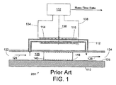
- FIG. 1 shows one prior art mass flowmeter 100, which includes a bypass section or flow body 110, a sensor tube 112, a laminar flow element (LFE) 118 and means for sensing the mass flow through the sensor tube 112.
- Bypass section 110 is typically (1) formed as a block shaped element, and (2) provided with a fluid flow passageway 125 that extends from an input port 122 to an output port 124 so that a fluid 126 may flow from the input port to the output port in a downstream direction indicated by arrows 128.
- LFE 118 is disposed within passageway 125 between input port 122 and output port 124 for restricting the flow of fluid 126 through the passageway.
- sensor tube 112 An upstream end of sensor tube 112 is coupled to the passageway 125 of bypass section 110 so as to be in fluid communication with the passageway 125 between input port 122 and LFE 118. Similarly, a downstream end of sensor tube 112 is coupled in fluid communication with the passageway 125 of bypass section 110 between LFE 118 and output port 124. A fixed portion of the total mass of fluid flowing from the input port 122 to the output port 124 flows through sensor tube 112.
- the internal cross-sectional diameter of sensor tube 112 is typically (but not necessarily) of capillary dimensions, and is fabricated from material characterized by a relatively high thermal conductivity (e.g., steel).
- splitting ratio The ratio of the mass of fluid flowing through sensor tube 112 to the total mass of fluid flowing from the input port 122 to the output port 124 is commonly referred to as the "splitting ratio".
- the splitting ratio is determined by the geometries of passageway 125, sensor tube 112, and LFE 118. Ideally, the splitting ratio remains constant over the entire range of mass flow rates that flowmeter 100 is used to measure. However, in practice the splitting ratio typically varies, at least slightly, according to a function of the rate of mass flow over the measurable range.
- the means for actually sensing and measuring the rate of mass flow through the sensor tube in the prior art embodiments described herein, as well as in all of the embodiments of the present invention, can be any arrangement for accomplishing that function.
- the means for sensing and measuring the rate of mass flow includes an upstream heater coil 114 and a downstream heater coil 116.
- Each of the heater coils 114, 116 includes a thermally sensitive resistive conductor that is tightly wound around a respective portion of sensor tube 112.
- Downstream heater coil 116 is disposed downstream of heater coil 114.
- the coils 114, 116 abut one another, or are separated by a relatively small gap for manufacturing convenience, and are electrically connected preferably at a node at or near the center of the tube 112.
- flowmeter 100 also includes an electronic measuring circuit 132.
- the upstream end of heater coil 114 is electrically connected to circuit 132 via a conductor 134
- the node electrically connecting the downstream end of heater coil 114 and the upstream end of heater coil 116 is electrically connected to circuit 132 via a conductor 136
- the downstream end of heater coil 116 is electrically connected to circuit 132 via a conductor 138.
- Each heater coil provides an electrical resistance that varies according to a function of the heater coil's temperature, and the temperature of each heater coil varies according to a function of the electrical current flowing through its resistive conductor.
- the resistances of the coils are matched as a function of temperature, i.e., the resistances and temperature coefficients of the coils are the same.
- the conductors of heater coils 114, 116 are not drawn to scale, and the diameter of these conductors is typically much smaller, relative to the sensor tube 112, than is depicted in the drawings.
- Circuit 132 preferably includes a constant current source for providing a current to flow through heater coils 114, 116, which in the absence of fluid flow through tube 112, are heated to the same initial temperature above the expected temperature of fluid 126. At the initial temperature heater coils 114, 116 generate and apply heat to sensor tube 112, as well as to the fluid 126 flowing through sensor tube 112 when fluid flows through the tube. When fluid 126 flows through the sensor tube 112, the flow of fluid has a cooling effect on coils 114, 116 and lowers their temperature as a function of the mass flow.
- Circuit 132 measures the mass flow rate of fluid flowing through sensor tube 112 by measuring the difference in temperature of the two coils, preferably by measuring the differences in resistances between the two coils.
- Circuit 132 generates a Mass Flow Rate signal representative of the total mass of fluid 126 flowing from the input port 122 to the output port 124 as a function of the measured difference in resistances (and thus measured temperatures) of coils 114 and 116 and as a function of the splitting ratio. Circuit 132 also compensates for any flow dependent variations and/or non-linearities in the splitting ratio when generating the Mass Flow Rate signal.
- U.S. Patent No. 5,461,913 issued to Hinkle et al. on October 31, 1995 , which is assigned to the present assignee, discloses one form of the measuring circuit 132 that may be used with a two coil sensing device.
- the splitting ratio of flowmeter 100 may be selected by selecting an appropriate LFE 118.
- LFE 118 i.e., for any particular splitting ratio
- flowmeter 100 is only suited for measuring mass flow rates that lie within a predetermined range. Measurement of the flow rate is only accurate if the fluid flow past the LFE is laminar and flow past the LFE will only be laminar within a predetermined range. Attempts to measure flow rates exceeding the range of a particular LFE require fluid pressures sufficient to create turbulent flow in passageway 125, and turbulent flow alters the splitting ratio and thereby detrimentally affects the accuracy of flowmeter 100.
- flowmeter 100 initially designed with a particular LFE 118 in order to measure a particular range of mass flow rates, can be adapted to measure a different range of mass flow rates simply by using a LFE 118 with different flow characteristics so as to adjust the splitting ratio appropriately.
- LFE 118 is a cylindrical rod defining one or more helical grooves or threads 140 that are cut in the outer cylindrical surface of the rod.
- the splitting ratio provided by LFE 118 is a function of the size and number of the helical grooves 140, so different types of LFEs may be produced simply by varying the size and number of the grooves.
- U.S. Patent No. 5,445,035 discloses a LFE comprising a cylindrical rod characterized by an outer diameter that is less than the inner diameter of the bypass section.
- the LFE is suspended inside and coaxial with the passageway of the bypass section by a set of screws so as to defme a cylindrical channel between the outer cylindrical surface of the LFE and the inner surface of the passageway of the bypass section through which fluid may flow. Since this LFE has a simple cylindrical shape (and no grooves) it may be reliably and relatively cheaply manufactured in large quantities. However, this LFE is disadvantageous because the screws used to support the LFE inside the passageway of the bypass section, and their adjustment, are mechanically complex.
- splitting ratio provided by such an LFE is strongly dependent on the uniformity of the radial thickness of the cylindrical flow channel (i.e., the alignment between the cylindrical axis of the LFE and the cylindrical axis of the bypass passageway). As is described generally in VISCOUS FLUID FLOW (Frank M. White, McGraw-Hill, Inc. 1974, pp.
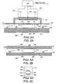
- FIGS 2A, 2B and 2C show another prior art mass flowmeter 200.
- Flowmeter 200 which is sold by the assignee of the present invention, is similar to flowmeter 100 (shown in Figure 1 ), however, flowmeter 200 is constructed using LFE 218 rather than LFE 118.
- LFE 218 is mounted in bypass section 110.
- LFE 218 is fabricated from a substantially fluid impermeable material such as steel.
- LFE 218 includes two end segments 220, 222 that are joined preferably together by and at opposite ends of a central segment 224 to form a one-piece (integral or monolithic) construction.
- each of the end segments 220, 222 are such that portions 221, of end segments 220, 222 contact the inner wall of passageway 125 of bypass section 110 and hold LFE 218 stationary with respect to bypass section 110.
- the outer surfaces of the end segments 220, 222 are formed so that they do not contact the entire circumference of the inner wall of passageway 125, but leave a pair of diametrically opposed gaps 226 between portions of end segments 220, 222 and the inner wall of passageway 125 so that fluid can pass therebetween.
- Central segment 224 is formed in the shape of a right angled cylinder, with the outer diameter of central segment 224 sufficiently small so as to provide a cylindrical channel 228 of uniform radial thickness (i.e., the central segment and passageway are coaxially aligned) between central segment 224 and inner wall of passageway 125 when the LFE 218 is positioned in bypass section 110.
- the gaps 226 between end segments 220, 222 and inner wall of passageway 125 and the passage between central segment 224 and inner wall of passageway 125 provide a fluid flow channel between LFE 218 and the inner wall of passageway 125 that permits laminar flow of fluid from input port 122 to output port 124.
- the size of the fluid flow channel, and therefore the splitting ratio provided by LFE 218, may be selected by appropriately selecting the outer diameter of central segment 224 (as well as the dimensions of end segments 220, 222) relative to the internal diameter of the passageway 125.
- the LFEs are not easily interchangeable.
- LFE 218 is typically cryogenically fitted into passageway 125 by cooling LFE 218 with, for example, liquid nitrogen to slightly shrink the dimensions of LFE 218, and by heating and thereby slightly expanding bypass section 110 so that LFE 218 may be slidably positioned within passageway 125.
- both components are allowed to return to the same (usually ambient) temperature so that LFE 218 expands and bypass section 110 contracts sufficiently and so that portions 221 of end segments 220, 222 contact the inner wall of passageway 125 of section 110, securely and rigidly holding LFE 218 in place.
- LFE 218 is advantageous since it can be precisely manufactured to very high tolerances, and therefore, large numbers of LFEs 218 can be produced that all provide substantially the same splitting ratio regardless of which one is mounted in a mass flowmeter. However, under current manufacturing practices this shrink fit approach adds time to the initial assembly time of the flowmeter. Further, LFE 218 can not be easily removed from tube 110 after it has been cryogenically mounted so the assembly tends to be considered permanent. Thus, once LFE 218 has been so mounted there is no way to easily adjust the splitting ratio provided by LFE 218.
- Another strategy for producing an adjustable splitting ratio is to use a "modifiable LFE".
- the splitting ratio provided by a modifiable LFE may be selectively adjusted after the LFE has been mounted within the bypass section.
- U.S. Patent No. 5,332,005 discloses a modifiable LFE that includes a fluid permeable, porous steel mesh that may be selectively compressed or expanded to adjust the fluid flow through the mesh.
- U.S. Patent No. 5,297,427 describes mechanical devices for inserting obstacles, such as a plate, into the bypass section for selectively adjusting the dimensions of the laminar flow channel.
- these patented devices are disadvantageous because they are mechanically complex.
- Another object of the present invention is to provide an improved mass flowmeter in which the splitting ratio can be easily adjusted.
- Yet another object of the present invention is to provide an improved flowmeter in which the dimensions of the laminar flow channel through the bypass section can be easily adjusted so as to reliably adjust the splitting ratio of the flowmeter.
- Another object of the present invention is to provide an improved LFE that may be easily positioned in and removed from the passageway of a bypass section of a flowmeter.
- Still another object of the present invention is to provide an improved flowmeter having an easily removable LFE so that different LFEs may be used to reliably set or adjust the splitting ratio of the flowmeter.
- Yet another object of the present invention is to provide an improved LFE that may be inexpensively produced, with identical LFEs providing repeatable performance characteristics when used in a mass flowmeter.
- Yet another object of the present invention is to provide an improved LFE for use in a mass flowmeter with consistent performance results.
- Yet another object of the present invention is to provide an improved mass flowmeter including a LFE and a bypass section, the maximum outer cross sectional dimension of the LFE being smaller than the maximum inner cross sectional dimension of the passageway provided in the bypass section.
- Yet another object of the present invention is to provide an improved mass flowmeter including a LFE in which at least a portion of the LFE is deliberately disposed in a selected "displaced" position (from the "coaxially aligned” position) within the passageway of a bypass section so as to define a flow channel between the LFE and the inner wall of the passageway of the bypass section correlated to a predetermined splitting ratio of the flowmeter.
- Yet another object of the present invention is to provide a cylindrical LFE for use in a cylindrical passageway defined by a bypass section, the LFE being mounted in a fully "displaced" position against the inner wall of the passageway.
- Yet another object of the present invention is to provide a flowmeter including a LFE disposed within a bypass section for defining a fluid flow channel, and a device for selectively adjusting the dimensions of the fluid flow channel.
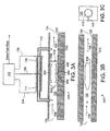
- FIGS 3A, 3B and 3C show a partially sectional from view of improved flowmeter 500 constructed according to the invention.
- Flowmeter 500 is constructed using adjustable LFE 518.
- Adjustable LFE 518 preferably is similar to LFE 218 (shown in Figures 2A-2C ) and includes two end segments 520, 522, and a central segment 524. Further, LFE 518 is preferably fabricated from a substantially fluid impervious material and is of integral or monolithic construction.
- the mass flow through an annular channel may be varied by as much as two and one half times by varying the displacement of the portion of this central segment between a first position wherein the central segment is coaxially aligned with the passageway 325, and a second position wherein at least a portion of the central segment is fully displaced so as to be in contact with the wall of the passageway.
- the splitting ratio provided by LFE 518 may be selectively adjusted between the two extreme positions by tightening or loosening screw 332 a predetermined amount correlated to the desired splitting ratio.
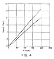
- Figure 4 shows a graph illustrating the adjustable splitting ratio that may be provided by LFE 518.
- the vertical axis of Figure 4 represents the difference in fluid pressures (measured in Torr) at input port 122 and output port 124, and the horizontal axis of Figure 4 represents mass flow (measured in sccm) through bypass section 310 when adjustable LFE 518 is mounted within bypass section 310.
- Figure 6 shows two curves, and each curve describes the experimentally measured flow characteristic provided by adjustable LFE 518 for a different position of screw 332. Each of the two curves is substantially linear showing that LFE 518 provides a substantially constant splitting ratio for the illustrated range of pressures and mass flows.
- screw 332 may be used to adjust the splitting ratio provided by LFE 518 after LFE 518 has been mounted in the passageway of bypass section 310, screw 332 may be used to compensate for any manufacturing defects or variations in LFE 518 that adversely affect the splitting ratio.
- use of adjustable LFE 518 may facilitate producing large numbers of flowmeters that all provide substantially the same performance characteristics.
- Adjustable LFE 518 may of course be used in other contexts as well.
- adjustable LFE 518 is of a monolithic or integral construction.
- central segment 524 may be resiliently joined to end segments 520, 522 (e.g., by springs) so that segment 524 can be displaced from the coaxial position by a preselected amount and will resiliently and repeatedly return to an original position when screw 332 is loosened to remove or reduce the biasing force applied by ball 334.
- FIG. 5 shows one embodiment of a pressure based mass flowmeter 1100 constructed according to the invention.
- Flowmeter 1100 includes bypass section 1109, an LFE 1118 (which is made in accordance with one or more of the improvements described herein, and is shown for illustration purposes to be similar to LFE 518 of Figures 3A, 3B and 3C ), as well as a differential pressure transducer 1110 and sensor tubes 1112, 1114.
- Transducer 1110 includes two input ports P1, P2, and transducer 1110 generates an output signal representative of the difference in the fluid pressures at ports P1 and P2.
- Sensor tube 1112 couples port P1 to a point of bypass section, 1109 between input port 1122 and LFE 1118, and sensor tube 1114 couples port P2 to a point of passageway of bypass section 1118 between LFE 1118 and output port 1124.
- the fluid pressure upstream of LFE 1118 is thus provided to port P1
- the fluid pressure downstream of LFE 1118 is provided to port P2.
- Transducer 1110 generates its output signal so that it is representative of the difference in fluid pressures upstream and downstream of LFE 1118, and as those skilled in the art will appreciate, this pressure difference is representative of the mass flow rate of fluid through the passageway of bypass section 1109.
Landscapes
- Physics & Mathematics (AREA)
- Fluid Mechanics (AREA)
- General Physics & Mathematics (AREA)
- Measuring Volume Flow (AREA)
Claims (7)
- Massenstromsteuerung, umfassend:eine Eingangsöffnung (122);eine Ausgangsöffnung (124);Mittel zum Begrenzen eines Durchgangswegs (325), umfassend ein erstes Rohr, das sich zwischen der Eingangsöffnung und der Ausgangsöffnung erstreckt und eine Strömungsrichtung der Strömung des Fluids zwischen der Eingangs- und Ausgangsöffnung begrenzt, wobei der Durchgangsweg durch einen Innenabschnitt begrenzt ist;ein verstellbares laminares Strömungselement (518), das in dem Durchgangsweg angeordnet ist, wobei ein Außenabschnitt in dem Innenabschnitt des Durchgangswegs angeordnet und so geformt ist, dass er einen Kanal dazwischen begrenzt; undMittel zum Messen der Massenstromgeschwindigkeit eines Fluids, das von der Eingangsöffnung zur Ausgangsöffnung strömt;gekennzeichnet durch:das laminare Strömungselement (518), das erste und zweite Segmente (520, 522) und ein mittleres Segment (524) aufweist, das zwischen dem ersten und zweiten Segment angeordnet ist, wobei das erste und zweite Segment jeweils Mittel aufweisen, um das erste und zweite Element im Wesentlichen ortsfest in dem Durchgangsweg zu halten, und Mittel zum Begrenzen einer Lücke in dem Durchgangsweg, um Fluid an dem ersten und zweiten Segment vorbeiströmen zu lassen, wobei die Mittel zum Halten des ersten und zweiten Segments einen jeweiligen ersten und zweiten Ankerabschnitt aufweisen, der ausreichend groß ist, um das jeweilige erste und zweite Segment in dem Durchgangsweg zu sichern, und das mittlere Segment (524) biegsam ist und weiterhin biegsam mit dem ersten und zweiten Segment gekoppelt ist und für ein selektives Biegen in dem Durchgangsweg konfiguriert und angeordnet ist;(F) Verstellmittel (332, 334), die mindestens eine verstellbare Schraube (332) umfassen, die sich durch mindestens eine Öffnung in dem Durchgangsweg erstreckt, um mindestens einen Abschnitt des laminaren Strömungselements selektiv zu versetzen, zum selektiven Positionieren zumindest des mittleren Segments (514) des verstellbaren laminaren Strömungselements (518) zwischen einer ersten Position, wobei der zwischen dem Innenabschnitt des Durchgangswegs und dem mittleren Abschnitt gebildete Kanal eine erste Querschnittsform hat, und einer zweiten Position, wobei der zwischen dem Innenabschnitt des Durchgangswegs und dem mittleren Abschnitt gebildete Kanal eine zweite Querschnittsform hat, die sich von der ersten Querschnittsform unterscheidet, und wobei das erste und zweite Segment (520, 522) des laminaren Strömungselements (518) im Verhältnis zu den Mitteln zum Begrenzen eines Durchgangswegs für jede der ersten und zweiten Positionen ortsfest bleiben; unddie Mittel zum Messen der Massenstromgeschwindigkeit eines Fluids, das von der Eingangsöffnung zur Ausgangsöffnung strömt, entweder:ein zweites Rohr (112), das ein erstes und ein zweites Ende aufweist, wobei das erste Ende mit dem ersten Rohr zwischen der Eingangsöffnung (122) und dem laminaren Strömungselement (518) gekoppelt ist und das zweite Ende mit dem ersten Rohr zwischen dem laminaren Strömungselement (518) und der Ausgangsöffnung (124) gekoppelt ist, und erste Heizmittel (114) zum Heizen eines ersten Abschnitts des zweiten Rohrs (112) und zweite Heizmittel (116) zum Heizen eines zweiten Abschnitts des zweiten Rohrs (112) und Mittel (132) zum Messen der Differenz zwischen dem ersten und dem zweiten Heizmittel einschließen, wobei die Temperaturdifferenz eine Massenstromgeschwindigkeit eines Fluids angibt, das durch das zweite Rohr strömt; oderMittel (1110) zum Messen eines Druckgefälles zwischen einem ersten Fluiddruck an einer Stelle zwischen der Eingangsöffnung und dem laminaren Strömungselement und einem zweiten Fluiddruck an einer Stelle zwischen dem laminaren Strömungselement und der Ausgangsöffnung einschließen, wobei das Druckgefälle eine Massenstromgeschwindigkeit von der Eingangsöffnung zur Ausgangsöffnung angibt.
- Vorrichtung nach Anspruch 1, wobei der Durchgangsweg (325) einen zylindrischen Querschnitt hat.
- Vorrichtung nach Anspruch 2, wobei das mittlere Segment (524) des laminaren Strömungselements einen zylindrischen Querschnitt hat.
- Vorrichtung nach Anspruch 3, wobei das mittlere Segment (524) des laminaren Strömungselements (518) zumindest einen Abschnitt einer Innenfläche des Durchgangswegs berührt, wenn das laminare Strömungselement in einer der ersten und zweiten Positionen angeordnet ist.
- Vorrichtung nach Anspruch 1, wobei ein Abschnitt eines Fluids, das von der Eingangsöffnung zur Ausgangsöffnung strömt, durch das zweite Rohr (112) nach Maßgabe eines Aufteilungsverhältnisses strömt, das als Funktion relativer Abmessungen des laminaren Strömungselements (518) und des ersten Durchgangswegs (325) bestimmt wird.
- Vorrichtung nach Anspruch 1, wobei das Mittel zum Halten des ersten Segments Mittel (944) zum radialen Erweitern zumindest eines Abschnitts des ersten Segments beinhaltet, um das laminare Strömungselement gegen eine Bewegung entlang des Durchgangswegs zu sichern.
- Vorrichtung nach Anspruch 1, wobei das Mittel zum Halten des zweiten Segments Mittel zum radialen Erweitern zumindest eines Abschnitts des zweiten Segments beinhaltet, um das laminare Strömungselement gegen eine Bewegung entlang des Durchgangswegs zu sichern.
Applications Claiming Priority (3)
| Application Number | Priority Date | Filing Date | Title |
|---|---|---|---|
| US852430 | 1997-05-07 | ||
| US08/852,430 US5824894A (en) | 1997-05-07 | 1997-05-07 | Mass flowmeter and laminar flow elements for use therein |
| PCT/US1998/009239 WO1998050762A1 (en) | 1997-05-07 | 1998-05-06 | Improved mass flowmeter and laminar flow elements for use therein |
Publications (3)
| Publication Number | Publication Date |
|---|---|
| EP0980507A1 EP0980507A1 (de) | 2000-02-23 |
| EP0980507A4 EP0980507A4 (de) | 2003-01-02 |
| EP0980507B1 true EP0980507B1 (de) | 2011-07-06 |
Family
ID=25313299
Family Applications (1)
| Application Number | Title | Priority Date | Filing Date |
|---|---|---|---|
| EP98920294A Expired - Lifetime EP0980507B1 (de) | 1997-05-07 | 1998-05-06 | Verbesserter massendurchflussmesser und laminare stromungselemente hierfür |
Country Status (5)
| Country | Link |
|---|---|
| US (1) | US5824894A (de) |
| EP (1) | EP0980507B1 (de) |
| JP (1) | JP3539975B2 (de) |
| KR (1) | KR100487671B1 (de) |
| WO (1) | WO1998050762A1 (de) |
Families Citing this family (22)
| Publication number | Priority date | Publication date | Assignee | Title |
|---|---|---|---|---|
| EP1046887A1 (de) * | 1999-04-19 | 2000-10-25 | Gamperl Gastechnik | Vorrichtung zum Messen eines Fluidmassendurchflusses |
| US6584828B2 (en) | 1999-12-17 | 2003-07-01 | Atc, Inc. | Method and apparatus of nondestructive testing a sealed product for leaks |
| US20020046612A1 (en) * | 2000-08-22 | 2002-04-25 | Fugasity Corporation | Fluid mass flow meter with substantial measurement range |
| US7243035B2 (en) * | 2002-05-24 | 2007-07-10 | Celerity, Inc. | System and method for mass flow detection device calibration |
| JP2005534007A (ja) * | 2002-07-19 | 2005-11-10 | セレリティー グループ,インコーポレイテッド | 流量センサ |
| US7121139B2 (en) * | 2004-11-12 | 2006-10-17 | Mks Instruments, Inc. | Thermal mass flow rate sensor having fixed bypass ratio |
| US7107834B2 (en) * | 2004-11-12 | 2006-09-19 | Mks Instruments, Inc. | Thermal mass flow rate sensor including bypass passageways and a sensor passageway having similar entrance effects |
| US7296465B2 (en) * | 2005-11-22 | 2007-11-20 | Mks Instruments, Inc. | Vertical mount mass flow sensor |
| US20080250854A1 (en) * | 2007-04-12 | 2008-10-16 | Junhua Ding | Mass flow device using a flow equalizer for improving the output response |
| DE202009009759U1 (de) | 2009-07-17 | 2009-09-24 | Bürkert Werke GmbH & Co. KG | Vorrichtung zur Bereitstellung von konditionierten Fluidströmungen |
| DE102009057418A1 (de) * | 2009-11-11 | 2011-05-12 | Dipl.-Ing. K. Dietzel Gmbh | Anordnung zur hochdynamischen Volumenstrommessung unter Druck stehender fluider Medien |
| US20110139268A1 (en) * | 2009-12-15 | 2011-06-16 | Scallen Richard E | Mounting System |
| US8899108B2 (en) * | 2011-10-20 | 2014-12-02 | Honeywell International Inc. | Flow sensor with multi-position laminar flow element having integrated bypass channels |
| US9080908B2 (en) | 2013-07-24 | 2015-07-14 | Jesse Yoder | Flowmeter design for large diameter pipes |
| US9746357B2 (en) * | 2015-04-24 | 2017-08-29 | Oes Medical Limited | Flow sensing meter |
| CN105424113B (zh) * | 2015-12-17 | 2018-08-07 | 成都瑞帆智达科技有限公司 | 一种螺旋布线的科里奥利质量流量计及布线方法 |
| CN110727294A (zh) * | 2018-07-17 | 2020-01-24 | 北京七星华创流量计有限公司 | 流体传感器及质量流量控制器 |
| JP2021536577A (ja) | 2018-09-18 | 2021-12-27 | スウェージロック カンパニー | 流体監視モジュール構造 |
| US10883865B2 (en) | 2018-09-19 | 2021-01-05 | Swagelok Company | Flow restricting fluid component |
| EP3734233B1 (de) | 2019-04-30 | 2023-12-13 | Fas Medic S.A. | Fluiderfassungsvorrichtung |
| US11519436B2 (en) | 2020-03-31 | 2022-12-06 | Hamilton Sundstrand Corporation | Serviceable laminar flow element |
| US11846531B2 (en) * | 2021-08-27 | 2023-12-19 | Sensia Llc | Ultrasonic flow meter with inner and outer flow channels |
Family Cites Families (10)
| Publication number | Priority date | Publication date | Assignee | Title |
|---|---|---|---|---|
| US3349619A (en) * | 1959-07-29 | 1967-10-31 | Meriam Instr Company | Laminar flow element and flow meter |
| US4524616A (en) * | 1983-09-02 | 1985-06-25 | Tylan Corporation | Adjustable laminar flow bypass |
| US4679585A (en) * | 1986-01-10 | 1987-07-14 | Mks Instruments, Inc. | Flowmeter-controlled valving |
| US4800754A (en) * | 1987-10-07 | 1989-01-31 | Sierra Instruments, Inc. | Wide-range, adjustable flowmeter |
| US5142907A (en) * | 1991-04-17 | 1992-09-01 | Mks Instruments, Inc. | Constant temperature gradient fluid mass flow transducer |
| EP0547617B1 (de) * | 1991-12-18 | 1996-07-10 | Pierre Delajoud | Massenströmungsmesser mit einschnürendem Element |
| US5305638A (en) * | 1992-03-20 | 1994-04-26 | Dxl International, Inc. | Mass flowmeter having non-adjustable flow splitter |
| US5297427A (en) * | 1992-09-03 | 1994-03-29 | Alicat Scientific, Inc. | Wide-range laminar flowmeter |
| US5332005A (en) * | 1992-11-06 | 1994-07-26 | Aalborg Instruments & Controls, Inc. | Laminar flow element and method for metering fluid flow |
| US5461913A (en) * | 1994-06-23 | 1995-10-31 | Mks Instruments, Inc. | Differential current thermal mass flow transducer |
-
1997
- 1997-05-07 US US08/852,430 patent/US5824894A/en not_active Expired - Lifetime
-
1998
- 1998-05-06 KR KR10-1999-7010218A patent/KR100487671B1/ko not_active Expired - Lifetime
- 1998-05-06 EP EP98920294A patent/EP0980507B1/de not_active Expired - Lifetime
- 1998-05-06 JP JP54844298A patent/JP3539975B2/ja not_active Expired - Lifetime
- 1998-05-06 WO PCT/US1998/009239 patent/WO1998050762A1/en not_active Ceased
Also Published As
| Publication number | Publication date |
|---|---|
| JP2001524216A (ja) | 2001-11-27 |
| WO1998050762A1 (en) | 1998-11-12 |
| KR100487671B1 (ko) | 2005-05-03 |
| EP0980507A1 (de) | 2000-02-23 |
| EP0980507A4 (de) | 2003-01-02 |
| KR20010012267A (ko) | 2001-02-15 |
| JP3539975B2 (ja) | 2004-07-07 |
| US5824894A (en) | 1998-10-20 |
Similar Documents
| Publication | Publication Date | Title |
|---|---|---|
| EP0980507B1 (de) | Verbesserter massendurchflussmesser und laminare stromungselemente hierfür | |
| US5850850A (en) | Flow controller, parts of flow controller, and related method | |
| US4800754A (en) | Wide-range, adjustable flowmeter | |
| US5285673A (en) | Method for in-line calibration verification of mass flow meters | |
| US4487213A (en) | Mass flow controller apparatus | |
| US5142907A (en) | Constant temperature gradient fluid mass flow transducer | |
| JP4090242B2 (ja) | 一定温度勾配の温度差型熱体積流量センサ | |
| KR20080072039A (ko) | 수직 설치형 질량유량센서 | |
| KR20040070179A (ko) | 열량 유동제어기의 열 관리 장치 및 그 방법 | |
| US6668642B2 (en) | Apparatus and method for thermal isolation of thermal mass flow sensor | |
| EP0904525B1 (de) | Heizer mit konischer heizdichtefunktion für massendurchflussmesser | |
| CN111854868B (zh) | 流体感测设备和质量流量控制器 | |
| KR20040070178A (ko) | 열량유동 센서의 열 분산 장치 및 그 방법 | |
| RU2126956C1 (ru) | Тепловой расходомер | |
| JPS6361918A (ja) | 挿入形熱式流量計 | |
| JP2024090786A (ja) | 抵抗体の製造方法、流体測定装置、流体制御装置、及び流体装置群 | |
| JPH0351715A (ja) | 吸入空気量検出装置 | |
| IL114519A (en) | Pressure gauge | |
| JPS63317725A (ja) | 流体流量の測定方法 |
Legal Events
| Date | Code | Title | Description |
|---|---|---|---|
| PUAI | Public reference made under article 153(3) epc to a published international application that has entered the european phase |
Free format text: ORIGINAL CODE: 0009012 |
|
| 17P | Request for examination filed |
Effective date: 19991129 |
|
| AK | Designated contracting states |
Kind code of ref document: A1 Designated state(s): DE FR GB NL |
|
| A4 | Supplementary search report drawn up and despatched |
Effective date: 20021112 |
|
| AK | Designated contracting states |
Kind code of ref document: A4 Designated state(s): DE FR GB NL |
|
| 17Q | First examination report despatched |
Effective date: 20050406 |
|
| RAP1 | Party data changed (applicant data changed or rights of an application transferred) |
Owner name: MKS INSTRUMENTS, INC. |
|
| GRAP | Despatch of communication of intention to grant a patent |
Free format text: ORIGINAL CODE: EPIDOSNIGR1 |
|
| GRAS | Grant fee paid |
Free format text: ORIGINAL CODE: EPIDOSNIGR3 |
|
| GRAA | (expected) grant |
Free format text: ORIGINAL CODE: 0009210 |
|
| AK | Designated contracting states |
Kind code of ref document: B1 Designated state(s): DE FR GB NL |
|
| REG | Reference to a national code |
Ref country code: GB Ref legal event code: FG4D |
|
| REG | Reference to a national code |
Ref country code: DE Ref legal event code: R096 Ref document number: 69842327 Country of ref document: DE Effective date: 20110901 |
|
| REG | Reference to a national code |
Ref country code: NL Ref legal event code: VDEP Effective date: 20110706 |
|
| PG25 | Lapsed in a contracting state [announced via postgrant information from national office to epo] |
Ref country code: NL Free format text: LAPSE BECAUSE OF FAILURE TO SUBMIT A TRANSLATION OF THE DESCRIPTION OR TO PAY THE FEE WITHIN THE PRESCRIBED TIME-LIMIT Effective date: 20110706 |
|
| PLBE | No opposition filed within time limit |
Free format text: ORIGINAL CODE: 0009261 |
|
| STAA | Information on the status of an ep patent application or granted ep patent |
Free format text: STATUS: NO OPPOSITION FILED WITHIN TIME LIMIT |
|
| 26N | No opposition filed |
Effective date: 20120411 |
|
| REG | Reference to a national code |
Ref country code: DE Ref legal event code: R097 Ref document number: 69842327 Country of ref document: DE Effective date: 20120411 |
|
| REG | Reference to a national code |
Ref country code: FR Ref legal event code: ST Effective date: 20130131 |
|
| PG25 | Lapsed in a contracting state [announced via postgrant information from national office to epo] |
Ref country code: FR Free format text: LAPSE BECAUSE OF NON-PAYMENT OF DUE FEES Effective date: 20120531 |
|
| PGFP | Annual fee paid to national office [announced via postgrant information from national office to epo] |
Ref country code: DE Payment date: 20170530 Year of fee payment: 20 Ref country code: GB Payment date: 20170530 Year of fee payment: 20 |
|
| REG | Reference to a national code |
Ref country code: DE Ref legal event code: R071 Ref document number: 69842327 Country of ref document: DE |
|
| REG | Reference to a national code |
Ref country code: GB Ref legal event code: PE20 Expiry date: 20180505 |
|
| PG25 | Lapsed in a contracting state [announced via postgrant information from national office to epo] |
Ref country code: GB Free format text: LAPSE BECAUSE OF EXPIRATION OF PROTECTION Effective date: 20180505 |