EP0980616B1 - Systeme et procede d'autodetection d'imprimante de reseau - Google Patents
Systeme et procede d'autodetection d'imprimante de reseau Download PDFInfo
- Publication number
- EP0980616B1 EP0980616B1 EP98922157A EP98922157A EP0980616B1 EP 0980616 B1 EP0980616 B1 EP 0980616B1 EP 98922157 A EP98922157 A EP 98922157A EP 98922157 A EP98922157 A EP 98922157A EP 0980616 B1 EP0980616 B1 EP 0980616B1
- Authority
- EP
- European Patent Office
- Prior art keywords
- printer
- network address
- job
- client terminal
- network
- Prior art date
- Legal status (The legal status is an assumption and is not a legal conclusion. Google has not performed a legal analysis and makes no representation as to the accuracy of the status listed.)
- Expired - Lifetime
Links
- 238000001514 detection method Methods 0.000 title description 4
- 238000000034 method Methods 0.000 claims description 28
- 230000004044 response Effects 0.000 claims description 4
- 238000004891 communication Methods 0.000 description 8
- 230000006870 function Effects 0.000 description 7
- 238000010586 diagram Methods 0.000 description 6
- 238000012544 monitoring process Methods 0.000 description 5
- 230000005540 biological transmission Effects 0.000 description 3
- 230000003993 interaction Effects 0.000 description 1
Images


Classifications
-
- H—ELECTRICITY
- H04—ELECTRIC COMMUNICATION TECHNIQUE
- H04L—TRANSMISSION OF DIGITAL INFORMATION, e.g. TELEGRAPHIC COMMUNICATION
- H04L9/00—Cryptographic mechanisms or cryptographic arrangements for secret or secure communications; Network security protocols
- H04L9/40—Network security protocols
Definitions
- the present invention relates to electronic networks having a plurality of client or agent terminals or systems, and more particularly to networks having one or more printers used by computers or other printer users within the network.
- the client terminals can comprise various types of systems such as a PC (personal computer), a printer, a router, a bridge, a tape drive, and the like.
- PC personal computer
- printer printer
- router bridge
- tape drive tape drive
- SNMP Simple Network Management Protocol
- the protocol is of the request-response type, and is typically carried out between a manager and an agent or client. The client may send asynchronous messages or "traps" to a management application.
- a plurality of clients in the form of computers are coupled to the network together with one or more printers and an intermediate spooler.
- Job requests for printing are transmitted by the client computers to the spooler which then stores spooled jobs in queues in the form of a scheduling list of print jobs to be done.
- the spooler then routes the job request to the printer.
- print job requests involve one-way communication in the sense that they are sent by the sending computer to the spooler using the known address of the spooler.
- the spooler then controls transmission of the job request to the printer.
- the network address of the printer is not normally known to the sending computer, so that direct communications from the sending computer to the printer are not possible. Instead, communications from the sending computer to the printer are made by way of the spooler.
- US 5,227,778 discloses a data communications network comprising a number of servers and a number of service provides.
- a protocol is employed for translating service names to network addresses.
- a server sends a multicast message to all service providers requesting a service needed by a user terminal connected to the server. In the request, the service is identified by function, rather than by address. Any node which provides this service which receives the request sends a reply message to the server, identifying said node by its network address.
- US 5,388,213 discloses a method for determining whether an alias is available for use in a communication system.
- a transmitting node transmits a signal including the alias and if a reply signal is received, it is deduced that the alias is in use.
- EP 0 691 772 discloses a system in which a terminal sends a message to a server requesting the address of another terminal. The server responds by providing the requested address.
- US 5,278,829 discloses a protocol in which a terminal stores a physical address to which data is to be sent. Time elapsed after storing said physical address is recorded, and upon subsequent usage of the stored physical address the terminal tests the validity of the stored address. If the stored address is valid, the terminal transmits data to the target host, but if the physical address is no longer valid the sending host transmits a broadcast packet on to the network to resolve the physical address of the target host.
- Adler RM Distributed coordination models for client/server computing
- computer, volume 28, No. 4, 1 April 1995 discussed extensions to the basic client server model that address one-to-many client/server interaction by considering how multiple services are requested, how those services are managed, and how clients receive responses.
- a method of detecting a network address of a receiving client terminal said receiving client terminal being part of a network in which a sending client terminal transmits data via an intermediate spooling system to the receiving client terminal, the receiving client terminal receiving jobs from one or more client terminals from a job queue maintained at the intermediate spooling system, the job queue being associated with a receiving client terminal and a network address of the client receiving terminal, comprising steps of:
- one or more clients in the form of computers are coupled through an intermediate spooler to one or more printers.
- a non-print job request is generated by a computer and is transmitted to the spooler.
- the non-print job is comprised of a job header and non-print data.
- the job header includes the network address of the sending computer, along with job identification and other information.
- the non-print job is routed by the spooler to the printer.
- the printer acknowledges receipt of the job by transmitting an acknowledgment back to the sending computer.
- the acknowledgment includes the network address of the printer, as well as the job identification and other information.
- the job request includes non-print or "dummy" print data
- no printing is performed at the printer.
- the included network address of the printer is identified by the computer and is stored in a memory field thereof for future use. Thereafter, when the need arises to send communications directly to the printer, such as when functions like configuration, set-up or printer monitoring are to be performed, the network address of the printer is retrieved from the memory field and is used to bypass the spooler and provide direct accessing of the printer.
- the acknowledgments comprise traps which are generated by the printer and sent to the sending computer in the form of a string of bytes.
- the network address of the printer occurs at a certain known location within the string of bytes. Consequently, identification and storage of the network address of the printer is accomplished by stripping off and storing from the string of bytes of the trap those bytes defining the network address of the printer.
- Fig. 1 shows an electronic network 10 of the type in which a method and a system in accordance with the invention may be used.
- SNMP Simple Network Management Protocol
- the network 10 includes a spooler 12 and a plurality of client terminals 14, 16, 18 and 24.
- the clients 14, 16, 18 and 24 can comprise such systems as a PC (personal computer), a printer, a router, a bridge, a tape drive, and the like. Where one of the clients 14, 16, 18 and 24 comprises a computer and another one of the clients comprises a printer, then as described hereafter, the computer client typically transmits job requests to the printer client by way of the spooler 12.
- the client 14 is assumed to be a host with management software, and the clients 16, 18 and 24 are assumed to be devices with an agent running (managed nodes).
- the client 16 is shown in Fig. 1 as a router, while the client 24 is shown in Fig. 1 and is described hereafter in terms of a printer.
- Fig. 2 depicts a portion of the network 10 which includes the client 14, the spooler 12 and the client (printer) 24.
- the client 14 is assumed to be a computer or other system (host) capable of generating and transmitting job requests to the printer 24 by way of the spooler 12.
- the computer 14 generates and transmits a job request to the spooler 12.
- the network address of the spooler 12 is known to the computer 14, so that the job request is sent directly to the spooler 12. Transmission of the job request to the spooler 12 utilizes a spool queue in which a schedule list is made up of jobs to be performed.
- the spooler 12 further processes the job request and then transmits it to the printer 24.
- the printer 24 acknowledges receipt of the job request by transmitting an acknowledgment to the client 14.
- the job request transmitted by the computer 14 has a job header which includes the network address of the computer 14. Consequently, the printer 24 is able to identify the job request as coming from the computer 14 and to send the acknowledgment.
- the acknowledgment takes the form of a trap in which the address of the printer 24 is included.
- the network address of the printer 24 is automatically determined by a method and system in which a job request is communicated by the spooler 12 to the printer 24 for the purpose of returning an acknowledgment from the printer 24 to the computer 14.
- the acknowledgment includes the network address of the printer 24, and the computer 14 identifies and stores the network address of the printer 24.
- the network address of the printer 24 is available for direct accessing of the printer 24 by the computer 14.
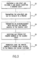
- Fig. 3 shows the successive steps in a preferred method according to the invention.
- a non-print job is generated by the sending client such as the computer 14.
- the non-print job includes a job header which identifies the computer 14.
- a second step 32 the non-print job is transmitted via the spooler 12 to the printer 24, in the manner previously described.
- the printer 24 responds to receipt of the non-print job from the spooler 12 by transmitting an acknowledgment to the computer 14.
- the acknowledgment includes the network address of the printer 24.
- the computer 14 identifies and stores the network address of the printer 24.
- the acknowledgment may comprise an SNMP trap in the form of a string of bytes, certain ones of which identify the network address of the printer 24.
- the bytes defining the network address of the printer 24 are detected and are stored in a memory field within the computer 14.
- the stored network address of the printer 24 may be used to provide direct access by the computer 14 to the printer 24 in cases where certain functions require such direct access.
- the generation and transmission of the non-print job will be better understood with reference to Fig. 4 which depicts the format of a typical non-print job 50 in accordance with the invention.
- the non-print job 50 includes a job header 52 together with non-print data 54.
- the job header 52 includes the network address of the sender, which in this case is the computer 14.
- the non-print data comprises "dummy" printing information in the sense that it does not result in any printing when received at the printer 24. This is because the non-print job 50 is generated and transmitted for the purpose of receiving an acknowledgment from the printer 24 so that the network address of the printer 24 can be identified and stored at the computer 14.
- the printer 24 acknowledges receipt of the non-print job 50 by transmitting an acknowledgment to the computer 14.
- the acknowledgment is shown as an SNMP trap 60 in Fig. 5.
- the SNMP trap 60 includes the network address of the printer 24, together with job identification and other information.
- the sending computer 14 detects and stores the network address of the printer contained in the SNMP trap 60. Detection and storage of the network address of the printer 24 is illustrated in Fig. 6.
- the SNMP trap 60 is shown as comprising a byte string 62.
- the string 62 is typically two hundred or more bytes in length.
- the printer address begins at a particular byte location along the string 62. Consequently, the computer 14 detects those bytes within the string 62 which identify the printer address, and stores such bytes in a memory field 64. Thereafter, the computer 14 retrieves the network address of the printer 24 each time it is necessary to provide direct access by the computer 14 to the printer 24.
- the computer 14 begins by generating the non-print job 50, including the job header 52 and the non-print data 54.
- the non-print job 50 is transmitted to the spooler 12, and then by the spooler 12 to the printer 24.
- the job header 52 is discarded by the printer 24.
- the non-print or "dummy" print data 54 is examined, and a determination is made that no printing is to take place.
- the printer 24 sends the acknowledgment trap 60 to the computer 14.
- the trap 60 includes the network address of the printer 24.
- the computer 14 detects the network address of the printer 24 in accordance with the appropriate positions within the byte string 62 of the trap 60, and stores the network address of the printer 24 in the memory field 64 of the computer 14. Thereafter, the printer address may be used to achieve direct access of the printer 24 by the computer 14, when needed.
- Fig. 8 provides a detailed example of a network 70 which employs a method and a system in accordance with the invention.
- the network 70 includes a client computer 72, a network server 74 and a network printer 76.
- the network server 74 provides spooling, and therefore functions as the spooler 12 in the prior figures of the drawings.
- the client computer 72 generates a job, which includes a job header and data, and transmits such job to the network server 74.
- the network server 74 sends the job header and data to the network printer 76.
- the network printer 76 acknowledges the job event with an acknowledgment trap that is sent to the client computer 72. Embedded in the trap is,information on the network printer 76 including particularly the network or IP (Internet) address.
- the client computer 72 also transmits server queries to the network server 74.
- the network printer 76 may transmit server specific printer status information to the network server 74. Having determined the network address of the printer 76 and stored the same in a memory field, the client computer 72 can thereafter directly access the network printer 76, when desired.
Landscapes
- Engineering & Computer Science (AREA)
- Computer Security & Cryptography (AREA)
- Computer Networks & Wireless Communication (AREA)
- Signal Processing (AREA)
- Accessory Devices And Overall Control Thereof (AREA)
- Computer And Data Communications (AREA)
Claims (15)
- Procédé de détection d'une adresse de réseau d'un terminal de client récepteur, ledit terminal de client récepteur faisant partie d'un réseau (10; 70) dans lequel un terminal de client expéditeur transmet des données par l'intermédiaire d'un système de spooling intermédiaire au terminal de client récepteur (24; 76), le terminal de client récepteur recevant des travaux d'un ou de plusieurs terminaux client à partir d'une file d'attente des travaux retenue au niveau du système de spooling intermédiaire, la file d'attente des travaux étant associée à un terminal de client récepteur et à une adresse de réseau du terminal de client récepteur, le procédé comprenant les étapes ci-dessous:production d'un travail (50) au niveau du terminal de client expéditeur (14; 72), le travail contenant une adresse de réseau du terminal de client expéditeur (14; 72);transmission du travail du terminal de client expéditeur (14; 72) vers la file d'attente des travaux retenue au niveau du système de spooling intermédiaire (12; 74) et associée au terminal de client récepteur (24; 76);transmission du travail de la file d'attente retenue au niveau du système de spooling intermédiaire (12; 74) vers l'adresse de réseau du terminal de client récepteur (24; 76);réponse à la réception du travail au niveau du terminal de client récepteur (24; 76) en transmettant à l'adresse de réseau du terminal de client expéditeur (14; 72) un accusé de réception contenant l'adresse de réseau du terminal de client récepteur (24; 76);détection et enregistrement de l'adresse de réseau du terminal de client récepteur (24; 76) au niveau du terminal de client expéditeur (14; 72); etutilisation ultérieure de l'adresse de réseau enregistrée du terminal de client récepteur (24; 76) pour communiquer directement entre le terminal de client expéditeur (14; 72) et le terminal de client récepteur (24; 76).
- Procédé selon la revendication 1, dans lequel l'étape de production d'un travail englobe l'étape de production d'un en-tête du travail (52) englobant l'adresse de réseau du terminal de client expéditeur (14; 72).
- Procédé selon la revendication 1, dans lequel l'accusé de réception comprend une chaíne d'octets (62) englobant des octets définissant l'adresse de réseau du terminal de client récepteur (24; 76), l'étape de détection et d'enregistrement comprenant l'étape de détection dans la chaíne d'octets (62) des octets définissant l'adresse de réseau et d'enregistrement des octets définissant l'adresse de réseau dans une mémoire.
- Procédé selon la revendication 1, dans lequel le terminal de client récepteur (24; 76) comprend une imprimante, l'étape de production d'un travail comprenant l'étape de production d'un travail de non impression (50).
- Procédé de détection automatique d'une adresse de réseau d'une imprimante (24; 76) en vue d'une utilisation ultérieure par un ordinateur (14; 72) en adressant directement l'imprimante (24; 76), l'imprimante (24; 76) et l'ordinateur (14; 72) faisant partie d'un réseau d'ordinateurs (10, 70) comprenant en plus un spooler (12; 74), l'imprimante recevant les travaux de l'ordinateur et des ordinateurs sur le réseau à partir d'une file d'attente des travaux retenue au niveau du spooler, la file d'attente des travaux étant associée à l'imprimante et à une adresse de réseau de l'imprimante, le procédé comprenant les étapes ci-dessous:production d'un travail (50) au niveau de l'ordinateur (14; 72) et transmission du travail de l'ordinateur (14; 72) vers le spooler (12; 74), le travail contenant une adresse de réseau de l'ordinateur (14; 72);transmission du travail de la file d'attente des travaux retenue au niveau du spooler (12; 74) vers l'adresse de réseau de l'imprimante (24; 76);réponse à la réception du travail au niveau de l'imprimante (24; 76) en transmettant un accusé de réception (60) de l'imprimante (24; 76) à une adresse de réseau de l'ordinateur (14; 72), l'accusé de réception englobant l'adresse de réseau de l'imprimante (24; 76);détection de l'adresse de réseau de l'imprimante (24; 76) au niveau de l'ordinateur (14; 72) et enregistrement de l'adresse de réseau en vue d'une utilisation future par l'ordinateur; etutilisation ultérieure de l'adresse de réseau enregistrée de l'imprimante (24; 76) pour communiquer directement entre l'ordinateur (14; 72) et l'imprimante (24; 76).
- Procédé selon la revendication 5, dans lequel l'étape de production d'un travail englobe l'étape de production d'un en-tête du travail (52) englobant une adresse de réseau de l'ordinateur (14; 72).
- Procédé selon la revendication 5, dans lequel l'étape de production d'un travail (50) englobe l'étape de production de données de non impression, de sorte que lorsque l'imprimante (24; 76) répond à la réception du travail, il n'y a pas d'impression.
- Procédé selon la revendication 5, dans lequel le réseau englobe un protocole de gestion du réseau simple (SNMP), l'accusé de réception transmis par l'imprimante (24; 76) comprenant un déroutement SNMP.
- Procédé selon la revendication 5, dans lequel l'accusé de réception comprend une chaíne d'octets (62), dont certains identifient l'adresse de réseau de l'imprimante (24; 76), l'étape de détection et d'enregistrement de l'adresse de réseau de l'imprimante (24; 76) comprenant l'étape de détection des octets de la chaíne d'octets (62) identifiant l'adresse de réseau de l'imprimante (24; 76) et d'enregistrement des octets identifiant l'adresse de réseau de l'imprimante (24; 76) dans un champ de mémoire dans l'ordinateur (14; 72).
- Réseau comprenant la combinaison d'un système de spooling (12, 74) et de plusieurs terminaux client (14, 16, 18, 24; 72, 76), un premier des plusieurs terminaux client (14; 72) englobant un moyen pour produire et transmettre des données contenant une adresse de réseau du premier des plusieurs terminaux client vers le système de spooling (12; 74) en vue de la mise sur une file d'attente au niveau du système de spooling (12; 74), la file d'attente étant associée à un deuxième des plusieurs terminaux client (24; 76) et à une adresse de réseau associée au deuxième des plusieurs terminaux client (24; 76), le système de spooling (12; 74) englobant un moyen pour transmettre les données de la file d'attente associée au deuxième des plusieurs terminaux client (24; 76) adressée à l'adresse de réseau du deuxième des plusieurs terminaux client (24; 76), le deuxième des plusieurs terminaux client englobant un moyen pour transmettre un accusé de réception (60) à l'adresse de réseau du premier terminal client (14; 72) en réponse à la réception des données transmises (50) par le premier terminal client, l'accusé de réception englobant l'adresse de réseau du deuxième terminal client (24; 76) et le premier terminal client (14; 72) englobant un moyen répondant à la réception de l'accusé de réception du deuxième terminal client en vue d'une détection automatique et d'un enregistrement de l'adresse de réseau du deuxième terminal client (24; 76).
- Réseau selon la revendication 10, dans lequel le moyen destiné à produire et à transmettre les données par l'intermédiaire du système de spooling (12; 74) vers un deuxième des plusieurs terminaux client (24; 76) englobe un moyen pour produire un en-tête du travail (52) englobant l'adresse de réseau du premier des plusieurs terminaux client (12; 74).
- Réseau selon la revendication 10, dans lequel le moyen de détection automatique et d'enregistrement englobe un moyen pour identifier un groupe d'octets dans une chaíne d'octets (62) de l'accusé de réception (60) comprenant l'adresse de réseau du deuxième terminal client (24; 76).
- Réseau selon la revendication 10, dans lequel le premier terminal client est constitué par un ordinateur (14; 72), le deuxième terminal client étant constitué par une imprimante (24; 76).
- Réseau selon la revendication 13, dans lequel le moyen destiné à produire et à transmettre des données par l'intermédiaire du système de spooling est destiné à produire et à transmettre un travail de non impression (50), l'imprimante répondant au travail de non impression en transmettant l'accusé de réception (60) et en ne faisant pas d'impression.
- Réseau selon la revendication 13, dans lequel le réseau englobe un protocole SNMP, l'accusé de réception comprenant un déroutement SNMP (60).
Applications Claiming Priority (3)
| Application Number | Priority Date | Filing Date | Title |
|---|---|---|---|
| US08/853,213 US5898823A (en) | 1996-07-04 | 1997-05-08 | Network printer auto-detection method and system |
| PCT/US1998/009463 WO1998051054A1 (fr) | 1997-05-08 | 1998-05-06 | Systeme et procede d'autodetection d'imprimante de reseau |
| US853213 | 2001-05-11 |
Publications (2)
| Publication Number | Publication Date |
|---|---|
| EP0980616A1 EP0980616A1 (fr) | 2000-02-23 |
| EP0980616B1 true EP0980616B1 (fr) | 2004-10-13 |
Family
ID=25315390
Family Applications (1)
| Application Number | Title | Priority Date | Filing Date |
|---|---|---|---|
| EP98922157A Expired - Lifetime EP0980616B1 (fr) | 1997-05-08 | 1998-05-06 | Systeme et procede d'autodetection d'imprimante de reseau |
Country Status (4)
| Country | Link |
|---|---|
| EP (1) | EP0980616B1 (fr) |
| CA (1) | CA2291061C (fr) |
| DE (1) | DE69826997T2 (fr) |
| WO (1) | WO1998051054A1 (fr) |
Families Citing this family (4)
| Publication number | Priority date | Publication date | Assignee | Title |
|---|---|---|---|---|
| US6748471B1 (en) | 2000-10-16 | 2004-06-08 | Electronics For Imaging, Inc. | Methods and apparatus for requesting and receiving a print job via a printer polling device associated with a printer |
| US7574545B2 (en) | 2000-10-16 | 2009-08-11 | Electronics For Imaging, Inc. | Method and apparatus for controlling a document output device with a control request stored at a server |
| DE60322453D1 (de) * | 2002-01-21 | 2008-09-11 | Canon Kk | System zum Bereitstellen von Diensten |
| US9436248B2 (en) | 2013-07-31 | 2016-09-06 | Freescale Semiconductor, Inc. | Data processing system with protocol determination circuitry |
Family Cites Families (4)
| Publication number | Priority date | Publication date | Assignee | Title |
|---|---|---|---|---|
| US5282270A (en) * | 1990-06-06 | 1994-01-25 | Apple Computer, Inc. | Network device location using multicast |
| US5278829A (en) * | 1991-01-10 | 1994-01-11 | Digital Equipment Corporation | Reduced broadcast algorithm for address resolution protocol |
| US5227778A (en) * | 1991-04-05 | 1993-07-13 | Digital Equipment Corporation | Service name to network address translation in communications network |
| JP3340846B2 (ja) * | 1994-07-05 | 2002-11-05 | 富士通株式会社 | Atm−lan及びサーバ及びatmアドレス管理方法 |
-
1998
- 1998-05-06 DE DE69826997T patent/DE69826997T2/de not_active Expired - Lifetime
- 1998-05-06 WO PCT/US1998/009463 patent/WO1998051054A1/fr not_active Ceased
- 1998-05-06 CA CA002291061A patent/CA2291061C/fr not_active Expired - Lifetime
- 1998-05-06 EP EP98922157A patent/EP0980616B1/fr not_active Expired - Lifetime
Also Published As
| Publication number | Publication date |
|---|---|
| WO1998051054A1 (fr) | 1998-11-12 |
| CA2291061A1 (fr) | 1998-11-12 |
| DE69826997T2 (de) | 2005-11-24 |
| EP0980616A1 (fr) | 2000-02-23 |
| CA2291061C (fr) | 2007-07-03 |
| DE69826997D1 (de) | 2004-11-18 |
Similar Documents
| Publication | Publication Date | Title |
|---|---|---|
| US5898823A (en) | Network printer auto-detection method and system | |
| US7546365B2 (en) | Network device management system and method of controlling same | |
| US6559965B1 (en) | Method and apparatus for establishing two-way communication with a remote printer | |
| US6574662B2 (en) | System for network-device management including collecting and storing of device attributes that change with time and device attributes that hardly change with time | |
| US6981036B1 (en) | Network device managing apparatus and method | |
| US7685288B2 (en) | Ad-hoc service discovery protocol | |
| US9998321B2 (en) | Method and apparatus for supporting duplicate suppression when issuing multicast queries using DNS-format message packets | |
| US20050038889A1 (en) | Network server and method of discovery of a network node | |
| US20030090716A1 (en) | Management information transmission apparatus, apparatus management apparatus, and apparatus management system | |
| WO2001082051A2 (fr) | Procede et systeme d'impression de radiodiffusion | |
| US20060161519A1 (en) | Prioritizing network management traffic | |
| CN102422606B (zh) | 网络通信装置及方法 | |
| US7664837B2 (en) | Data transmitting system using multicast addresses for networked resources | |
| US7114006B2 (en) | Apparatus and method to remotely change IP address of server | |
| EP0980616B1 (fr) | Systeme et procede d'autodetection d'imprimante de reseau | |
| JP4231241B2 (ja) | ネットワークにおける通信 | |
| US7680896B2 (en) | Obtaining or sending information to a device on a network by a client apparatus | |
| JP4139541B2 (ja) | プリンタおよびプリンタジョブデータの転送方法 | |
| US20130107886A1 (en) | Transferring data in a network | |
| US7664841B2 (en) | Selective activation of TCP/IP link and traffic | |
| KR100524058B1 (ko) | 사무 기기의 에러 발생시 처리 방법 | |
| KR20010011078A (ko) | 네트워크 프린터의 인쇄방법 | |
| JP3826906B2 (ja) | 通信管理装置 | |
| WO2001098857A2 (fr) | Procede de gestion de serveurs a distance sur le reseau | |
| KR100584824B1 (ko) | 이동 통신 시스템의 이기종 보드간 제어 메시지 전달 방법 |
Legal Events
| Date | Code | Title | Description |
|---|---|---|---|
| PUAI | Public reference made under article 153(3) epc to a published international application that has entered the european phase |
Free format text: ORIGINAL CODE: 0009012 |
|
| 17P | Request for examination filed |
Effective date: 19991207 |
|
| AK | Designated contracting states |
Kind code of ref document: A1 Designated state(s): DE FR GB |
|
| RAP1 | Party data changed (applicant data changed or rights of an application transferred) |
Owner name: HITACHI KOKI IMAGING SOLUTIONS, INC. |
|
| 17Q | First examination report despatched |
Effective date: 20031104 |
|
| GRAP | Despatch of communication of intention to grant a patent |
Free format text: ORIGINAL CODE: EPIDOSNIGR1 |
|
| GRAS | Grant fee paid |
Free format text: ORIGINAL CODE: EPIDOSNIGR3 |
|
| GRAA | (expected) grant |
Free format text: ORIGINAL CODE: 0009210 |
|
| AK | Designated contracting states |
Kind code of ref document: B1 Designated state(s): DE FR GB |
|
| REG | Reference to a national code |
Ref country code: GB Ref legal event code: FG4D |
|
| REF | Corresponds to: |
Ref document number: 69826997 Country of ref document: DE Date of ref document: 20041118 Kind code of ref document: P |
|
| PLBE | No opposition filed within time limit |
Free format text: ORIGINAL CODE: 0009261 |
|
| STAA | Information on the status of an ep patent application or granted ep patent |
Free format text: STATUS: NO OPPOSITION FILED WITHIN TIME LIMIT |
|
| ET | Fr: translation filed | ||
| 26N | No opposition filed |
Effective date: 20050714 |
|
| REG | Reference to a national code |
Ref country code: FR Ref legal event code: PLFP Year of fee payment: 19 |
|
| PGFP | Annual fee paid to national office [announced via postgrant information from national office to epo] |
Ref country code: GB Payment date: 20160520 Year of fee payment: 19 |
|
| REG | Reference to a national code |
Ref country code: FR Ref legal event code: PLFP Year of fee payment: 20 |
|
| PGFP | Annual fee paid to national office [announced via postgrant information from national office to epo] |
Ref country code: FR Payment date: 20170523 Year of fee payment: 20 Ref country code: DE Payment date: 20170523 Year of fee payment: 20 |
|
| GBPC | Gb: european patent ceased through non-payment of renewal fee |
Effective date: 20170506 |
|
| PG25 | Lapsed in a contracting state [announced via postgrant information from national office to epo] |
Ref country code: GB Free format text: LAPSE BECAUSE OF NON-PAYMENT OF DUE FEES Effective date: 20170506 |
|
| REG | Reference to a national code |
Ref country code: DE Ref legal event code: R071 Ref document number: 69826997 Country of ref document: DE |