EP0980658A1 - Pupitre de lecture adapté pour ordinateur et procédé permettant d'obtenir une position de travail ergonomique - Google Patents
Pupitre de lecture adapté pour ordinateur et procédé permettant d'obtenir une position de travail ergonomique Download PDFInfo
- Publication number
- EP0980658A1 EP0980658A1 EP98250292A EP98250292A EP0980658A1 EP 0980658 A1 EP0980658 A1 EP 0980658A1 EP 98250292 A EP98250292 A EP 98250292A EP 98250292 A EP98250292 A EP 98250292A EP 0980658 A1 EP0980658 A1 EP 0980658A1
- Authority
- EP
- European Patent Office
- Prior art keywords
- test
- vessel
- module according
- liquid
- test module
- Prior art date
- Legal status (The legal status is an assumption and is not a legal conclusion. Google has not performed a legal analysis and makes no representation as to the accuracy of the status listed.)
- Granted
Links
Images


Classifications
-
- G—PHYSICS
- G06—COMPUTING OR CALCULATING; COUNTING
- G06F—ELECTRIC DIGITAL DATA PROCESSING
- G06F11/00—Error detection; Error correction; Monitoring
- G06F11/07—Responding to the occurrence of a fault, e.g. fault tolerance
- G06F11/0703—Error or fault processing not based on redundancy, i.e. by taking additional measures to deal with the error or fault not making use of redundancy in operation, in hardware, or in data representation
- G06F11/0706—Error or fault processing not based on redundancy, i.e. by taking additional measures to deal with the error or fault not making use of redundancy in operation, in hardware, or in data representation the processing taking place on a specific hardware platform or in a specific software environment
- G06F11/0733—Error or fault processing not based on redundancy, i.e. by taking additional measures to deal with the error or fault not making use of redundancy in operation, in hardware, or in data representation the processing taking place on a specific hardware platform or in a specific software environment in a data processing system embedded in an image processing device, e.g. printer, facsimile, scanner
-
- A—HUMAN NECESSITIES
- A47—FURNITURE; DOMESTIC ARTICLES OR APPLIANCES; COFFEE MILLS; SPICE MILLS; SUCTION CLEANERS IN GENERAL
- A47B—TABLES; DESKS; OFFICE FURNITURE; CABINETS; DRAWERS; GENERAL DETAILS OF FURNITURE
- A47B19/00—Reading-desks; Lecterns; Pulpits, i.e. free-standing
Definitions
- the invention relates to a test module for testing optical parts for defects according to the preamble of claim 1.
- Mass-produced optical parts e.g. Contact lenses
- need to look for defects like scratches, Blowholes or broken edges can be checked.
- image-resolving sensor observes Errors that lead to refraction or scattering of the light appear then dark.
- the image information supplied by the image-resolving sensor becomes evaluated by image processing means. The parts identified as defective will be then discarded.
- test module must therefore enable high throughput.
- Known test devices are relative slow so that throughput is severely limited.
- known ones Test devices are complicated to set up.
- the invention is based on the problem of having a test module of the type mentioned at the beginning simple means so that a large throughput of optical to be tested Sharing is possible.
- the parts to be tested e.g. Contact lenses
- the test part sinks dampened to the floor in the transport container.
- the container can be shaped so that the part has a substantially defined position on the floor occupies.
- the transport containers are when passing through the test station completed by transparent cover, the inside - at least in the area of Test light beam - is wetted by the liquid. Since the lighting by the transparent lid, the wetting of the lid ensures that none Fluctuations in the surface of the liquid such as waves caused by the Movement of the transport containers occurs, which can impair the measurement.
- This Training of the transport vessels enables the optical inspection of a Contact lens can be carried out directly in the transport container and no separate Process steps are required.
- By simultaneously transporting the contact lenses in the transport containers and the inspection of the contact lenses inside the containers is a enables fast throughput of contact lenses to be checked and efficient and economic audit guaranteed. Since the transport containers through a lid during completed, external influences such as the wave movement of the Liquid can be excluded and a reproducible measurement is available with everyone Vessel of the train enabled. After the test, the tested optical part is removed again the liquid removed and transported as "good” or "defective".
- the vessel is guided along an endless path through the test station, so that a simple and inexpensive control of each vessel is possible. Because of that Another means of handling that runs synchronously with each vessel stands for everyone a sufficient amount of time is available for each handling step, so that despite a high throughput a reliable inspection of the contact lenses is given.
- the invention makes it simple in terms of structure and control Test module has been created because the transport containers themselves already have optical Properties for testing the optical parts are equipped and the effort for the control of the individual transport vessels through the arrangement along one endless path is minimized.
- the vessels can be prismatic with a bottom made of transparent material and can be locked at their open end by the transparent cover. Then the vessels at the test station are illuminated from the lid side and by means of the Sensor observed through the floor. Through the prismatic, to the The dimensions of the optical parts to be tested are adapted to the shape of the vessels ensures that the parts to be tested in the liquid on the Sink the floor and take a defined position there.
- the optical part to be tested lying on the inside of the floor is covered by imaging optical means with a focus area, which is the optical part to be tested includes, imaged on the image-resolving sensor.
- the thickness of the bottom and the The distance between the bottom and the lid is so large that the lid as well the outside of the ground outside the focus range of the imaging optical Means lies.
- the lid and the outside of the bottom can be handled by handling the Vessels themselves can be provided with scratches or the like. But these areas are outside the focus range of the imaging of the optical part on the sensor. Scratches, dust or other defects on the lid or the outside are therefore from the sensor is not “seen” sharply and cannot make any errors in the optical being tested Partially pretend.
- the test module has means for removing of bubbles from the liquid before the measurement.
- the bladder hits Means work with ultrasound, for example.
- the endless path formed by a chain of vessels around a first and a second Rotary table with parallel axes of rotation running at a distance from one another is.
- First handling means for inserting the optical parts to be tested and the Carrying out the test run around with the first turntable, and second Handling means for taking out the tested optical parts run with the second turntable.
- the first handling means can be a gripper Place a lid on the vessel after inserting the optical one to be checked Partly and to remove the lid after the test included.
- the second Handling means can contain a gripper, which in an entrance area of the second turntable is immersed in the liquid and grips the optical part and the in an output region of the second rotary table with the optical part from the Liquid can be moved out. Between the entrance area and the exit area of the second rotary table, a liquid exchange area can be provided which sucks the liquid out of the vessels and replaces it with new liquid becomes. Between the turntables can cross the direction of movement of the chain of vessels ongoing funding for the supply of parts to be tested and for the removal of tested parts Parts can be arranged.
- the handling means can by longitudinal cams be controlled by the endless path along which the handling means pass. The liquid-filled vessels can be driven continuously. Such Curve control is easy to implement. Through the interlocking of the individual vessels there is a fixed coupling, so that the total tax expense is minimized.
- the first handling means simply rotate around the first rotary table, the second handling means with the second. It is therefore not a separate one Sync required. Even if the vessel chain and the turntables to achieve high throughput, remains relatively fast for the various functions of Handling means sufficient time. The handling means therefore only need moving relatively slowly. This makes it possible to use the handling means, e.g. the hub of grippers, easily controlled by fixed cams on which the Pass the handling equipment with the chain of vessels. By following the Handling means can also drive the vascular chain continuously with constant Speed, not stepwise. This also simplifies things.
- test modules constructed in this way are comparatively small, simple and inexpensive. It is therefore possible to use a test device for testing optical parts for defects, in particular of contact lenses produced as injection molded parts in the manner to build that a plurality of test modules of the aforementioned type, each with one Computer is connected to a common server. If one of the test modules fails then not the entire testing capacity, which leads to an interruption in production lead, but a large percentage remains, e.g. of 80% of the test capacity receive.
- 10 denotes a vessel in which one manufactured as an injection molded part Contact lens 12 should be checked for defects such as scratches, blowholes or the like.
- the vessel 10 has a prismatic, especially a cylindrical basic shape. At a distance from the Inner wall 14 of the vessel 10, the contact lens 12 lies on the bottom of the vessel.
- the vessel has a thick, transparent bottom 16.
- the vessel 10 is on his completed by a plug-like cover 18, which consists of a transparent material.
- the lid 18 has a head piece 20 which on the sits on the upper edge 22 of the vessel 10, and a stopper part 24 which fits into the vessel 10 protrudes. Between the stopper part 24 and the inner wall 14 of the vessel 10 is a Gap 26 formed.
- the vessel 10 is filled with a liquid 28, namely water.
- the Liquid 28 wets the lower end face 30 of the lid 18 and rises somewhat in the Gap 26 high.
- the vessel 10 is illuminated from above with directed lighting illuminated by a lighting device 32.
- the light falls through the transparent Cover 18 and the liquid 28 on the contact lens to be checked 12.
- the contact lens 12 is observed by an image-resolving sensor 34.
- the Contact lens 12 is imaged on sensor 34 by an imaging optical system 36.
- Optical errors of the contact lens cause a scattering or deflection of the incident Light. These errors therefore appear dark in the image.
- the illustration by the imaging optical system 36 has a focus range, which is shown in FIG Double arrow 38 is indicated.
- the end face 30 of the lid 18 and the outer surface of the Bottom 16 are outside this focus area 38. These areas can be in the Handling the vessel or the lid have received 18 scratches or the like.
- a test module is generally designated by 46 in FIG. 2.
- the test module 46 has two Rotary tables 48 and 50, which are spaced apart with axes parallel to each other are arranged.
- a vessel chain 52 runs around the rotary tables 48 and 50.
- the vessel chain 52 consists of lined-up, liquid-filled vessels 10 of the in Fig. 1st shown type.
- the vessels 10 of the vessel chain 52 move on an endless Path around the two turntables 48 and 50.
- Between the two turntables 48 and 50 is a conveyor 54 for feeding contact lenses to be checked and for removing them tested contact lenses arranged.
- the conveyor 54 extends above the Vessel chain 52 and transverse to those running between the rotary tables 48 and 50 straight sections of the vessel chain 52.
- the rotary tables 48 and 50 run continuously, i.e. with constant rotational speed in order.
- Handling devices in the form of grippers 56 and 58 run with the rotary tables 48 and 50 also continuously around. For the sake of clarity, only one is shown in FIG. 2 Grippers 56 and 58 shown. In fact, the grippers 56 and 58 are so radiating arranged that over each of the vessels 10 of the vessel chain 52 on the outer Half circles of the rotary tables 48 and 50, such a gripper 56 and 58 stands and with the Vessel 10 revolves. There is therefore no relative movement on these outer semicircles in the circumferential direction between the vessels 10 and the grippers 56 and 58, respectively.
- the grippers 56 and 58 are raised and lowered by cams 60 and 62, respectively.
- the cams 60 and 62 extend in a circle around the axes of rotation of the respective rotary tables 48 and 50.
- a straight "entry-side" section 64 of the vessel chain 52 Contact lenses, which are supplied via the conveyor 54, into the vessels 10 inserted. They sink on a section 66 of the circulation of the vessels in the liquid to the bottom of the vessels 10, as shown in Fig. 1.
- a section 68 of the circulation is the lid 18 (Fig. 1) by the gripper 56 standing above the respective vessel 10 placed on the vessel 10.
- the gripper 56 is placed over the cam 60 lowered.
- the gripper 56 has a suction head which sucks the lid 18 onto the Put on vessel 10 and then let go.
- the gripper 56 can by (not shown) Cams can also be moved laterally to the vessel to the top opening of the vessel 10 to insert the contact lens 12 or to release the measurement.
- the bubbles are removed in a section 70 possibly can adhere to the contact lens 12 to be tested. This can be done using ultrasound happened and is not shown here in detail.
- the Contact lens 12 sunk to the bottom of the vessel 10, the bubbles are removed and the lid 18 is put on and is wetted on its underside by the liquid.
- the contact lens is tested in the under 1 described manner.
- the gripper 56 is thereby a Cam control moved out of the beam path of the lighting device 32.
- the lid 18 is lifted off the vessel 10 again.
- the gripper 56 is lowered again onto the cover 18.
- the suction head sucks the lid and then lifts it further from the gripper 56 over the inner one, not half of the turntable 48 wrapped around by the vascular chain 52.
- the gripper 56 then the lid 18 in again Section 68 onto a new vessel 10 equipped with a contact lens 12.
- the vessel 10 without the lid 18 then runs in the lower, straight line shown in FIG. 2 Section of the endless path to the second turntable 50.
- Handling means in the form of grippers 58 likewise run with the second rotary table 50 um, of which only one is shown in FIG. 2 for the sake of clarity.
- the grabs extend in a star shape to the individual vessels 10 of the vessel chain 52 and run on the outer semicircle facing away from the turntable 48 and facing away in FIG one of the vessels 10 with.
- the grippers 58 can be moved up and down by the cams 62.
- a section 76 the grippers 58 dip into the vessels 10.
- a section 78 are by means of suction heads which are attached to the grippers 58, which are based on the Vessels 10 lying contact lenses 78 sucked.
- Sections 80 and 82 serve to exchange the liquid.
- section 80 the Aspirated liquid.
- section 82 fresh liquid is filled. That can over Channels happen that are provided in the grippers 58.
- Section 84 over the cams 62, the grippers 58 with the sucked-in contact lenses 12 the vessels 10 lifted out.
- the grippers 58 with the suctioned contact lenses 12 then move on inner semicircle of the turntable 50.
- the vessels 10 freed from the contact lenses 12 continue to move along the upper straight section of FIG endless path to the turntable 48.
- the procedure described is repeated there.
- the Grippers 58 place the tested contact lenses in an area 86 on the Conveyor 54. These checked contact lenses are then, like arrow 88 indicates transported away from the conveyor.
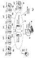
- Fig. 3 shows schematically a test device for contact lenses, which a plurality of Test modules 46A, 46B, 46D, 46E and 46F of the type shown in Fig. 2.
- Each the test modules 46A, 46B, 46C, 46E and 46F is connected to an associated computer 90A, 90B, 90C, 90D, 90E and 90F connected.
- the computers 90A, 90B, 90C, 90D, 90E and 90F are in a network 92 connected to a server 94.
- the network 92 expediently contains a second server 94A for redundancy.
- the network 92 is with one Monitor 96 and an input keyboard 98 connected.
- the network 92 can Data line 100 for remote diagnosis of any errors of the test equipment a central office, e.g. the manufacturer of the test device.
Landscapes
- Engineering & Computer Science (AREA)
- Theoretical Computer Science (AREA)
- Computer Vision & Pattern Recognition (AREA)
- Quality & Reliability (AREA)
- Physics & Mathematics (AREA)
- General Engineering & Computer Science (AREA)
- General Physics & Mathematics (AREA)
- Investigating Materials By The Use Of Optical Means Adapted For Particular Applications (AREA)
- Eyeglasses (AREA)
- Tables And Desks Characterized By Structural Shape (AREA)
Priority Applications (2)
| Application Number | Priority Date | Filing Date | Title |
|---|---|---|---|
| EP98250292A EP0980658B1 (fr) | 1998-08-17 | 1998-08-17 | Pupitre de lecture adapté pour ordinateur et procédé permettant d'obtenir une position de travail ergonomique |
| AT98250292T ATE266955T1 (de) | 1998-08-17 | 1998-08-17 | Computergerechtes arbeitsstehpult und verfahren zur realisierung einer ergonomischen arbeitshaltung |
Applications Claiming Priority (1)
| Application Number | Priority Date | Filing Date | Title |
|---|---|---|---|
| EP98250292A EP0980658B1 (fr) | 1998-08-17 | 1998-08-17 | Pupitre de lecture adapté pour ordinateur et procédé permettant d'obtenir une position de travail ergonomique |
Publications (2)
| Publication Number | Publication Date |
|---|---|
| EP0980658A1 true EP0980658A1 (fr) | 2000-02-23 |
| EP0980658B1 EP0980658B1 (fr) | 2004-05-19 |
Family
ID=8234599
Family Applications (1)
| Application Number | Title | Priority Date | Filing Date |
|---|---|---|---|
| EP98250292A Expired - Lifetime EP0980658B1 (fr) | 1998-08-17 | 1998-08-17 | Pupitre de lecture adapté pour ordinateur et procédé permettant d'obtenir une position de travail ergonomique |
Country Status (2)
| Country | Link |
|---|---|
| EP (1) | EP0980658B1 (fr) |
| AT (1) | ATE266955T1 (fr) |
Citations (4)
| Publication number | Priority date | Publication date | Assignee | Title |
|---|---|---|---|---|
| EP0252274A2 (fr) * | 1986-07-10 | 1988-01-13 | Hellmuth Moll | Dispositif pour s'asseoir en forme de chaise |
| AT387314B (de) * | 1986-12-10 | 1989-01-10 | Kmentt Ingomar | Tisch |
| DE3930466A1 (de) | 1989-09-12 | 1991-03-21 | Rudolf Prof Dipl I Strzygowski | Stehpult |
| DE4104462A1 (de) * | 1990-02-16 | 1991-08-22 | Eckart Dr Ing Baum | Vorrichtung zum positionieren und bewegen von geraetschaften bei einem einzelperson-arbeitsplatz |
-
1998
- 1998-08-17 EP EP98250292A patent/EP0980658B1/fr not_active Expired - Lifetime
- 1998-08-17 AT AT98250292T patent/ATE266955T1/de not_active IP Right Cessation
Patent Citations (4)
| Publication number | Priority date | Publication date | Assignee | Title |
|---|---|---|---|---|
| EP0252274A2 (fr) * | 1986-07-10 | 1988-01-13 | Hellmuth Moll | Dispositif pour s'asseoir en forme de chaise |
| AT387314B (de) * | 1986-12-10 | 1989-01-10 | Kmentt Ingomar | Tisch |
| DE3930466A1 (de) | 1989-09-12 | 1991-03-21 | Rudolf Prof Dipl I Strzygowski | Stehpult |
| DE4104462A1 (de) * | 1990-02-16 | 1991-08-22 | Eckart Dr Ing Baum | Vorrichtung zum positionieren und bewegen von geraetschaften bei einem einzelperson-arbeitsplatz |
Also Published As
| Publication number | Publication date |
|---|---|
| ATE266955T1 (de) | 2004-06-15 |
| EP0980658B1 (fr) | 2004-05-19 |
Similar Documents
| Publication | Publication Date | Title |
|---|---|---|
| EP1105707B1 (fr) | Module d'essai pour controler la presence eventuelle de defauts sur des pieces optiques | |
| DE3234563C2 (de) | Optischer, automatischer Analyse- und Meßapparat | |
| DE69324221T2 (de) | Verfahren und Vorrichtung zur Inspektion von ophthalmischen Linsen | |
| DE2349901C3 (de) | Vorrichtung zum reihenweisen Transport von geradlinig hintereinander angeordneten Probengefäßen | |
| DE3906281A1 (de) | Verfahren und vorrichtung zum optischen ueberpruefen des aussehens chipartiger bauteile und zum sortieren der chipartigen bauteile | |
| DE3717907A1 (de) | Automatische probenabgabevorrichtung fuer automatische chemische analysiergeraete | |
| DE102010018823B4 (de) | Schwebstofferkennung in mit Flüssigkeit befüllten Behältnissen | |
| DE102017127946B4 (de) | Verformungsverifikationssystem und Verformungsverifikationsverfahren für eine Fahrzeugkarosserie | |
| CH448565A (de) | Chromatografisches Verfahren und Gerät zu seiner Durchführung | |
| EP1198704B1 (fr) | Procede et dispositif d'inspection de receptacles transparents | |
| DE4221107A1 (de) | Verfahren und Vorrichtung zum Sortieren von Kapseln | |
| EP2276671B1 (fr) | Dispositif ainsi que procede pour l'inspection de bouteilles ou recipients analogues | |
| DE3038210A1 (de) | Verfahren zum messen einer agglutinationsreaktion und reaktionsgefaess zur verwendung bei dem verfahren | |
| DE69621151T2 (de) | Verfahren und gerät für die sedimentation und die optische untersuchung von in einem fluidium schwebenden teilchen, sowie küvette zur ausführung diese verfahrens | |
| WO1989008836A1 (fr) | Procede et dispositif de detection de defauts dans des pieces embouties a la piece ou dans d'autres pieces a usiner | |
| DE1623036C3 (de) | Einrichtung zur Blutgruppenbestimmung | |
| EP2924419A2 (fr) | Dispositif d'inspection et procédé d'inspection par transparence de récipients | |
| DE1963795A1 (de) | Vorrichtung zum automatischen Analysieren fluessiger Proben | |
| DE2164109A1 (de) | Flaschenpruefvorrichtung | |
| DE68924867T2 (de) | Automatische Vorrichtung für kapillare Elektrophorese. | |
| DE3346532C2 (fr) | ||
| DE4322865A1 (de) | Gerät zur Messung der Farbe von Glas, insbesondere von Glasbruch | |
| DE2249490C3 (fr) | ||
| DE4202172C1 (en) | Testing surface and shape of similar small objects e.g. medicinal tabless - directing cameras onto rotatable discs with recesses for objects quality control | |
| DE69030957T2 (de) | Probentransportsystem für optisches überwachungssystem |
Legal Events
| Date | Code | Title | Description |
|---|---|---|---|
| PUAI | Public reference made under article 153(3) epc to a published international application that has entered the european phase |
Free format text: ORIGINAL CODE: 0009012 |
|
| AK | Designated contracting states |
Kind code of ref document: A1 Designated state(s): AT BE CH DK FI FR GB IT LI NL SE |
|
| AX | Request for extension of the european patent |
Free format text: AL;LT;LV;MK;RO;SI |
|
| 17P | Request for examination filed |
Effective date: 20000322 |
|
| K1C3 | Correction of patent application (complete document) published |
Effective date: 20000223 |
|
| AKX | Designation fees paid |
Free format text: AT BE CH DK FI FR GB IT LI NL SE |
|
| 17Q | First examination report despatched |
Effective date: 20020531 |
|
| REG | Reference to a national code |
Ref country code: DE Ref legal event code: 8566 |
|
| GRAP | Despatch of communication of intention to grant a patent |
Free format text: ORIGINAL CODE: EPIDOSNIGR1 |
|
| GRAS | Grant fee paid |
Free format text: ORIGINAL CODE: EPIDOSNIGR3 |
|
| GRAA | (expected) grant |
Free format text: ORIGINAL CODE: 0009210 |
|
| AK | Designated contracting states |
Kind code of ref document: B1 Designated state(s): AT BE CH DK FI FR GB IT LI NL SE |
|
| PG25 | Lapsed in a contracting state [announced via postgrant information from national office to epo] |
Ref country code: NL Free format text: LAPSE BECAUSE OF FAILURE TO SUBMIT A TRANSLATION OF THE DESCRIPTION OR TO PAY THE FEE WITHIN THE PRESCRIBED TIME-LIMIT Effective date: 20040519 Ref country code: IT Free format text: LAPSE BECAUSE OF FAILURE TO SUBMIT A TRANSLATION OF THE DESCRIPTION OR TO PAY THE FEE WITHIN THE PRE;WARNING: LAPSES OF ITALIAN PATENTS WITH EFFECTIVE DATE BEFORE 2007 MAY HAVE OCCURRED AT ANY TIME BEFORE 2007. THE CORRECT EFFECTIVE DATE MAY BE DIFFERENT FROM THE ONE RECORDED.SCRIBED TIME-LIMIT Effective date: 20040519 Ref country code: FI Free format text: LAPSE BECAUSE OF FAILURE TO SUBMIT A TRANSLATION OF THE DESCRIPTION OR TO PAY THE FEE WITHIN THE PRESCRIBED TIME-LIMIT Effective date: 20040519 |
|
| REG | Reference to a national code |
Ref country code: GB Ref legal event code: FG4D Free format text: NOT ENGLISH |
|
| REG | Reference to a national code |
Ref country code: CH Ref legal event code: EP |
|
| PG25 | Lapsed in a contracting state [announced via postgrant information from national office to epo] |
Ref country code: AT Free format text: LAPSE BECAUSE OF NON-PAYMENT OF DUE FEES Effective date: 20040817 |
|
| PG25 | Lapsed in a contracting state [announced via postgrant information from national office to epo] |
Ref country code: SE Free format text: LAPSE BECAUSE OF FAILURE TO SUBMIT A TRANSLATION OF THE DESCRIPTION OR TO PAY THE FEE WITHIN THE PRESCRIBED TIME-LIMIT Effective date: 20040819 Ref country code: GB Free format text: LAPSE BECAUSE OF NON-PAYMENT OF DUE FEES Effective date: 20040819 Ref country code: DK Free format text: LAPSE BECAUSE OF FAILURE TO SUBMIT A TRANSLATION OF THE DESCRIPTION OR TO PAY THE FEE WITHIN THE PRESCRIBED TIME-LIMIT Effective date: 20040819 |
|
| PG25 | Lapsed in a contracting state [announced via postgrant information from national office to epo] |
Ref country code: LI Free format text: LAPSE BECAUSE OF NON-PAYMENT OF DUE FEES Effective date: 20040831 Ref country code: CH Free format text: LAPSE BECAUSE OF NON-PAYMENT OF DUE FEES Effective date: 20040831 Ref country code: BE Free format text: LAPSE BECAUSE OF NON-PAYMENT OF DUE FEES Effective date: 20040831 |
|
| GBT | Gb: translation of ep patent filed (gb section 77(6)(a)/1977) |
Effective date: 20040909 |
|
| NLV1 | Nl: lapsed or annulled due to failure to fulfill the requirements of art. 29p and 29m of the patents act | ||
| ET | Fr: translation filed | ||
| BERE | Be: lapsed |
Owner name: KERN, BEATRICE Effective date: 20040831 |
|
| PLBE | No opposition filed within time limit |
Free format text: ORIGINAL CODE: 0009261 |
|
| STAA | Information on the status of an ep patent application or granted ep patent |
Free format text: STATUS: NO OPPOSITION FILED WITHIN TIME LIMIT |
|
| GBPC | Gb: european patent ceased through non-payment of renewal fee |
Effective date: 20040819 |
|
| REG | Reference to a national code |
Ref country code: CH Ref legal event code: PL |
|
| PG25 | Lapsed in a contracting state [announced via postgrant information from national office to epo] |
Ref country code: FR Free format text: LAPSE BECAUSE OF NON-PAYMENT OF DUE FEES Effective date: 20050429 |
|
| 26N | No opposition filed |
Effective date: 20050222 |
|
| REG | Reference to a national code |
Ref country code: FR Ref legal event code: ST |
|
| BERE | Be: lapsed |
Owner name: *KERN BEATRICE Effective date: 20040831 |