EP0980724A2 - Ensemble guide de poinçon - Google Patents
Ensemble guide de poinçon Download PDFInfo
- Publication number
- EP0980724A2 EP0980724A2 EP99115992A EP99115992A EP0980724A2 EP 0980724 A2 EP0980724 A2 EP 0980724A2 EP 99115992 A EP99115992 A EP 99115992A EP 99115992 A EP99115992 A EP 99115992A EP 0980724 A2 EP0980724 A2 EP 0980724A2
- Authority
- EP
- European Patent Office
- Prior art keywords
- punch guide
- stripper plate
- punch
- retaining clip
- groove
- Prior art date
- Legal status (The legal status is an assumption and is not a legal conclusion. Google has not performed a legal analysis and makes no representation as to the accuracy of the status listed.)
- Withdrawn
Links
Images


Classifications
-
- B—PERFORMING OPERATIONS; TRANSPORTING
- B21—MECHANICAL METAL-WORKING WITHOUT ESSENTIALLY REMOVING MATERIAL; PUNCHING METAL
- B21D—WORKING OR PROCESSING OF SHEET METAL OR METAL TUBES, RODS OR PROFILES WITHOUT ESSENTIALLY REMOVING MATERIAL; PUNCHING METAL
- B21D28/00—Shaping by press-cutting; Perforating
- B21D28/24—Perforating, i.e. punching holes
- B21D28/34—Perforating tools; Die holders
-
- B—PERFORMING OPERATIONS; TRANSPORTING
- B21—MECHANICAL METAL-WORKING WITHOUT ESSENTIALLY REMOVING MATERIAL; PUNCHING METAL
- B21D—WORKING OR PROCESSING OF SHEET METAL OR METAL TUBES, RODS OR PROFILES WITHOUT ESSENTIALLY REMOVING MATERIAL; PUNCHING METAL
- B21D45/00—Ejecting or stripping-off devices arranged in machines or tools dealt with in this subclass
- B21D45/003—Ejecting or stripping-off devices arranged in machines or tools dealt with in this subclass in punching machines or punching tools
- B21D45/006—Stripping-off devices
-
- Y—GENERAL TAGGING OF NEW TECHNOLOGICAL DEVELOPMENTS; GENERAL TAGGING OF CROSS-SECTIONAL TECHNOLOGIES SPANNING OVER SEVERAL SECTIONS OF THE IPC; TECHNICAL SUBJECTS COVERED BY FORMER USPC CROSS-REFERENCE ART COLLECTIONS [XRACs] AND DIGESTS
- Y10—TECHNICAL SUBJECTS COVERED BY FORMER USPC
- Y10T—TECHNICAL SUBJECTS COVERED BY FORMER US CLASSIFICATION
- Y10T83/00—Cutting
- Y10T83/869—Means to drive or to guide tool
- Y10T83/8821—With simple rectilinear reciprocating motion only
- Y10T83/8841—Tool driver movable relative to tool support
- Y10T83/8853—Including details of guide for tool or tool support
-
- Y—GENERAL TAGGING OF NEW TECHNOLOGICAL DEVELOPMENTS; GENERAL TAGGING OF CROSS-SECTIONAL TECHNOLOGIES SPANNING OVER SEVERAL SECTIONS OF THE IPC; TECHNICAL SUBJECTS COVERED BY FORMER USPC CROSS-REFERENCE ART COLLECTIONS [XRACs] AND DIGESTS
- Y10—TECHNICAL SUBJECTS COVERED BY FORMER USPC
- Y10T—TECHNICAL SUBJECTS COVERED BY FORMER US CLASSIFICATION
- Y10T83/00—Cutting
- Y10T83/929—Tool or tool with support
- Y10T83/9411—Cutting couple type
- Y10T83/9423—Punching tool
-
- Y—GENERAL TAGGING OF NEW TECHNOLOGICAL DEVELOPMENTS; GENERAL TAGGING OF CROSS-SECTIONAL TECHNOLOGIES SPANNING OVER SEVERAL SECTIONS OF THE IPC; TECHNICAL SUBJECTS COVERED BY FORMER USPC CROSS-REFERENCE ART COLLECTIONS [XRACs] AND DIGESTS
- Y10—TECHNICAL SUBJECTS COVERED BY FORMER USPC
- Y10T—TECHNICAL SUBJECTS COVERED BY FORMER US CLASSIFICATION
- Y10T83/00—Cutting
- Y10T83/929—Tool or tool with support
- Y10T83/9457—Joint or connection
- Y10T83/9473—For rectilinearly reciprocating tool
- Y10T83/9476—Tool is single element with continuous cutting edge [e.g., punch, etc.]
Definitions
- the present invention relates to a punch guide assembly and, more particularly, a punch guide having an opening therein for insertion of a retaining clip for holding a stripper plate in place in the punch guide, the retaining clip being easily removable from the opening in the punch guide to release the stripper plate and allow removal thereof from the punch guide.
- a punch unit for use in a punch press generally includes a punch driver connected with a punch.
- the punch driver includes a punch head at its back end.
- a preloaded compression means such as a compression spring, is provided between the punch head and the punch guide.
- a punch guide receives and guides the punch.
- a stripper plate is positioned in the bottom of the punch guide. The stripper plate is a hardened plate having an opening with the same shape as that of the punch tip.
- a ram presses down on the punch head forcing the punch tip to enter a workpiece.
- the preloaded compression means then forces the punch and punch driver out of the workpiece and back to their normal position.
- the stripper plate prevents the edges of the cut hole from following the punch tip.
- the punch and stripper plate are often replaced due to wear or because a different shaped punch tip is required. Because the opening in the stripper must closely match the shape of the punch tip, when the punch is changed, it is also typically necessary to change the stripper plate.
- a stripper plate is insertable into the open end.
- a retaining clip is insertable into the opening in the sidewall from the exterior of the punch guide. The retaining clip engages the stripper plate when inserted into the punch guide to retain the stripper plate therein.
- the retaining clip is readily accessible from the exterior of the punch guide to allow removal of the retaining clip, thereby releasing the stripper plate from the punch guide.
- the retaining clip includes two side arms connected at ends thereof by a bar to form a C-shape. These two side arms frictionally engage a groove in opposite sidewalls of the stripper plate when the retaining clip is inserted into the opening in the wall of the punch guide.
- the punch guide may include a groove in the interior sidewall which corresponds to the groove in the stripper plate. This groove is engaged by protrusions extending outward from the retaining clip to hold the stripper plate more securely in place in the punch guide.
- an object of the invention to provide a punch guide assembly in which the stripper plate may be removed and replaced without disassembly of the remaining portion of the punch tool.
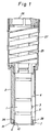
- Figure 1 shows a completely assembled punch tool with the stripper plate and retaining clip of the invention shown schematically therein.
- the punch tool includes a punch 1 which is guided linearly displaceably in a punch guide 2.
- a punch driver 25 is connected with the punch 1.
- the punch driver 25 includes a punch head 26 at its back end.
- a preloaded compression means, such as a compression spring 27, is provided between the punch head 26 and the punch guide 2. Rotation of the punch 1 in relation to the punch guide 2 is prevented by rotation preventing means such as a pin 3 fixed to the punch 1 which engages an interior longitudinal groove 4 in the punch guide 2.
- An axial groove 5 is opened radially outwardly so that means on the punch press machine, not shown, can engage the groove 5 from the exterior and non-rotatingly maintain it on the punch press machine.
- a stripper plate 6 is inserted into the lower open end of the punch guide 2 and prevented from further movement into punch guide 2 by shoulder 24 which engages the top end 28 of the stripper plate 6. Stripper plate 6 is then fastened on the lower end of the punch guide 2 by means of a retaining clip 7.
- the stripper plate 6 includes an aperture 11 through which the punch tip is guided.
- the size and shape of aperture 11 will of course vary depending upon the size and shape of the punch tip.
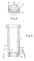
- the stripper plate 6 also includes a lug 12 which extends perpendicularly upwardly from the top end 28 and is designed to fit inside one or more longitudinal slots 13 in the interior of the punch guide 2, as shown in Figure 3. This helps to retain the stripper plate 6 in the proper position in the punch guide 2 so that it does not rotate with respect to the punch guide 2.
- Figure 4 shows a preferred embodiment of retaining clip 7.
- the retaining clip includes two side arms 8.
- Side arms 8 are connected at their ends by a bar 9, forming a C-shape.
- the arms 8 resiliently engage the sidewalls of the stripper plate 6.
- the stripper plate include a groove 10 in the sidewalls as shown in Figures 2 and 3 for receiving the side arms 8 of the retaining clip 7.
- the groove 10 preferably extends around the entire circumference of the stripper plate 6 as the stripper plate 6 may be rotated to different positions, i.e. ,such that lug 12 may be received within different longitudinal slots 13 inside the punch guide 2.
- punch guide 2 includes openings 15 for receiving respective side arms 8 of the retaining clip 7. These openings 15 are aligned with groove 10 when the stripper plate 6 is fully inserted into the punch guide 2.
- Punch guide 2 may include slight indentations 23 in the exterior wall near opening 16 which allow retaining clip 7 to be more easily grasped when removed from the punch guide.
- Punch guide 2 may also include an opening 16 for receiving protrusion 17 on the retaining clip. Protrusion 17, when positioned in opening 16, helps to prevent the retaining clip 7 from rotating relative to the punch guide 2 and stripper plate 6. Thus, when retaining clip 7 is inserted into punch guide 2 the edge 19 of protrusion 17 lies flat against the groove 10 as shown in Figure 7.
Landscapes
- Engineering & Computer Science (AREA)
- Mechanical Engineering (AREA)
- Punching Or Piercing (AREA)
Applications Claiming Priority (2)
| Application Number | Priority Date | Filing Date | Title |
|---|---|---|---|
| US09/135,358 US6196103B1 (en) | 1998-08-17 | 1998-08-17 | Punch guide assembly |
| US135358 | 1999-05-21 |
Publications (2)
| Publication Number | Publication Date |
|---|---|
| EP0980724A2 true EP0980724A2 (fr) | 2000-02-23 |
| EP0980724A3 EP0980724A3 (fr) | 2002-12-11 |
Family
ID=22467742
Family Applications (1)
| Application Number | Title | Priority Date | Filing Date |
|---|---|---|---|
| EP99115992A Withdrawn EP0980724A3 (fr) | 1998-08-17 | 1999-08-16 | Ensemble guide de poinçon |
Country Status (6)
| Country | Link |
|---|---|
| US (1) | US6196103B1 (fr) |
| EP (1) | EP0980724A3 (fr) |
| JP (1) | JP2004500242A (fr) |
| AU (1) | AU5251699A (fr) |
| CA (1) | CA2346950C (fr) |
| WO (1) | WO2000009301A1 (fr) |
Families Citing this family (15)
| Publication number | Priority date | Publication date | Assignee | Title |
|---|---|---|---|---|
| AU2003252113A1 (en) * | 2002-07-26 | 2004-02-16 | Humdinger, Inc. | Stripper-plate alignment system and die set |
| US20060266178A1 (en) * | 2005-05-24 | 2006-11-30 | Lane Punch Corporation | Punch Stripper |
| US7913618B2 (en) * | 2007-06-21 | 2011-03-29 | Mate Precision Tooling, Inc. | Punch press tool for stamping successive multicharacter impressions into a workpiece |
| US9211581B2 (en) * | 2007-09-21 | 2015-12-15 | Wilson Tool International Inc. | Stripper assemblies and components thereof for multi-tool punch assemblies |
| US7954404B2 (en) | 2008-04-29 | 2011-06-07 | Mate Precision Tooling, Inc. | Punch device with adjustment subassembly as retrofit insert or as original equipment |
| US8327745B2 (en) | 2008-11-06 | 2012-12-11 | Wilson Tool International Inc. | Punch assemblies and methods for modifying |
| US8413561B2 (en) * | 2009-11-10 | 2013-04-09 | Mate Precision Tooling, Inc. | Multiple punch and die assembly |
| US9409223B2 (en) | 2011-11-11 | 2016-08-09 | Wilson Tool International Inc. | Punch assemblies and universal punch therefor |
| US8707841B2 (en) | 2011-11-11 | 2014-04-29 | Wilson Tool International Inc. | Punch assemblies and universal punch therefor |
| US10265756B2 (en) | 2012-02-06 | 2019-04-23 | Mate Precision Tooling, Inc. | Punch assembly with steel punch point insert removably secured therein |
| US8997617B2 (en) | 2012-03-14 | 2015-04-07 | Mate Precision Tooling, Inc. | Punch assembly with quick attach punch point and stripper plate removably secure thereon |
| US10646913B2 (en) | 2015-02-09 | 2020-05-12 | Mate Precision Tooling, Inc. | Punch assembly with replaceable punch tip |
| USD822725S1 (en) | 2015-12-31 | 2018-07-10 | Mate Precision Tooling, Inc. | Punch insert |
| USD820328S1 (en) | 2015-12-31 | 2018-06-12 | Mate Precision Tooling, Inc. | Punch insert |
| US11667051B2 (en) | 2020-09-23 | 2023-06-06 | Wilson Tool International Inc. | Punch assemblies and toolless systems thereof for tip retention and release |
Family Cites Families (20)
| Publication number | Priority date | Publication date | Assignee | Title |
|---|---|---|---|---|
| US2225342A (en) * | 1939-03-18 | 1940-12-17 | Allied Steel & Conveyors Inc | Punch stripping device |
| US2999407A (en) * | 1960-06-03 | 1961-09-12 | Arrow Tools Inc | Axial impact tool and work-retainer combination |
| US3079824A (en) | 1960-08-09 | 1963-03-05 | Houdaille Industries Inc | Punching device having a spring biased stripper |
| US3298409A (en) * | 1964-05-22 | 1967-01-17 | Black & Decker Mfg Co | Retaining member |
| US3326580A (en) * | 1965-01-07 | 1967-06-20 | Worthington Corp | Locking assembly having means to prevent axial and torsional movement |
| US3391954A (en) * | 1966-01-26 | 1968-07-09 | Charles B. Callahan | Retaining ring apparatus |
| US3566730A (en) | 1969-02-25 | 1971-03-02 | Houdaille Industries Inc | Punch press having ram with stripping means |
| FR2127331A5 (fr) | 1971-03-04 | 1972-10-13 | Jestin Paul | |
| US3759130A (en) | 1972-04-13 | 1973-09-18 | Mate Punch And Die Co | Replaceable tip shear proof punch |
| US3871254A (en) | 1973-04-13 | 1975-03-18 | Jr Lawrence V Whistler | Means for piercing and stripping thick material |
| US3958476A (en) | 1975-06-30 | 1976-05-25 | Houdaille Industries, Inc. | Punching device with punch retainer |
| US4104941A (en) | 1976-09-21 | 1978-08-08 | S. B. Whistler & Sons, Inc. | Assembly for enabling close tolerance punching with a reusable system |
| US4248111A (en) | 1979-07-16 | 1981-02-03 | Wilson Tool Company | Punch guide assembly |
| US4446767A (en) | 1981-11-30 | 1984-05-08 | Wilson Tool Company | Locking ring stripper plate assembly |
| DE3703649A1 (de) | 1987-02-06 | 1988-08-18 | Heraeus Gmbh W C | Werkzeug zum stanzen von komplexen stanzbildern aus einem metallband |
| US4947719A (en) | 1987-09-01 | 1990-08-14 | S. B. Whistler & Sons, Inc. | Punch and die system |
| US5271303A (en) * | 1990-07-26 | 1993-12-21 | Strippit, Inc. | Stripper plate retaining ring |
| US5131303A (en) | 1991-08-12 | 1992-07-21 | Wilson Tool International | Punch assembly |
| US5301580A (en) * | 1992-10-07 | 1994-04-12 | Wilson Tool International, Inc. | Locking ring stripper plate assembly |
| JPH10113725A (ja) * | 1996-10-08 | 1998-05-06 | Amada Metrecs Co Ltd | パンチプレス用金型におけるストリッパプレート着脱方法およびその装置 |
-
1998
- 1998-08-17 US US09/135,358 patent/US6196103B1/en not_active Expired - Lifetime
-
1999
- 1999-08-03 CA CA002346950A patent/CA2346950C/fr not_active Expired - Lifetime
- 1999-08-03 JP JP2000564782A patent/JP2004500242A/ja active Pending
- 1999-08-03 WO PCT/US1999/017517 patent/WO2000009301A1/fr not_active Ceased
- 1999-08-03 AU AU52516/99A patent/AU5251699A/en not_active Abandoned
- 1999-08-16 EP EP99115992A patent/EP0980724A3/fr not_active Withdrawn
Also Published As
| Publication number | Publication date |
|---|---|
| CA2346950C (fr) | 2008-01-08 |
| WO2000009301A1 (fr) | 2000-02-24 |
| AU5251699A (en) | 2000-03-06 |
| CA2346950A1 (fr) | 2000-02-24 |
| EP0980724A3 (fr) | 2002-12-11 |
| US6196103B1 (en) | 2001-03-06 |
| JP2004500242A (ja) | 2004-01-08 |
Similar Documents
| Publication | Publication Date | Title |
|---|---|---|
| EP0980724A2 (fr) | Ensemble guide de poinçon | |
| US5884546A (en) | Punch unit | |
| US6647836B1 (en) | Lockable telescoping screwdriver | |
| EP1058605B1 (fr) | Ensemble a outil de poinconnage reglable, a changement rapide, et procede de reglage | |
| US5361925A (en) | Terminal box | |
| KR880001407B1 (ko) | 다목적 공구 | |
| US7975587B2 (en) | Punching tool | |
| US10751781B2 (en) | Punch assembly with replaceable punch tip | |
| US4674367A (en) | Apparatus for inserting and removing screws | |
| JP2732547B2 (ja) | ロックリングストリッパ板組立体 | |
| EP1038608B1 (fr) | Collecteur de tiges pour outil d'installation de rivets aveugles | |
| CA1287793C (fr) | Systeme d'estampage | |
| US3245694A (en) | Removable ball retainer block | |
| JPH05123210A (ja) | 各種バンドのサイズ合わせと修理用の装置 | |
| EP0280506A2 (fr) | Dispositif pour la préhension d'une vis | |
| EP1324447B1 (fr) | Outil à dénuder pour câbles | |
| CN113365753A (zh) | 用于冲压机的冲头单元 | |
| US8037793B2 (en) | Stripper plate mounting apparatus | |
| US2818015A (en) | Can end marking means | |
| EP1322010B1 (fr) | Outil de dénudage d'un câble | |
| US6401345B1 (en) | Tool head for a dual punch tool | |
| WO2001008852A1 (fr) | Dispositif extracteur | |
| US5119545A (en) | Apparatus for servicing loom feeder plate assembly | |
| CN223130630U (zh) | 一种枪嘴结构以及击打工具 | |
| US4535540A (en) | "Hole-in-one" metal punch drive unit |
Legal Events
| Date | Code | Title | Description |
|---|---|---|---|
| PUAI | Public reference made under article 153(3) epc to a published international application that has entered the european phase |
Free format text: ORIGINAL CODE: 0009012 |
|
| AK | Designated contracting states |
Kind code of ref document: A2 Designated state(s): AT BE CH CY DE DK ES FI FR GB GR IE IT LI LU MC NL PT SE |
|
| AX | Request for extension of the european patent |
Free format text: AL;LT;LV;MK;RO;SI |
|
| PUAL | Search report despatched |
Free format text: ORIGINAL CODE: 0009013 |
|
| AK | Designated contracting states |
Kind code of ref document: A3 Designated state(s): AT BE CH CY DE DK ES FI FR GB GR IE IT LI LU MC NL PT SE |
|
| AX | Request for extension of the european patent |
Free format text: AL;LT;LV;MK;RO;SI |
|
| 17P | Request for examination filed |
Effective date: 20030605 |
|
| AKX | Designation fees paid |
Designated state(s): DE FR GB IT |
|
| 17Q | First examination report despatched |
Effective date: 20031209 |
|
| STAA | Information on the status of an ep patent application or granted ep patent |
Free format text: STATUS: THE APPLICATION IS DEEMED TO BE WITHDRAWN |
|
| 18D | Application deemed to be withdrawn |
Effective date: 20040420 |