EP0980725A2 - Dichtungselement und Verfahren zur Herstellung desselben - Google Patents
Dichtungselement und Verfahren zur Herstellung desselben Download PDFInfo
- Publication number
- EP0980725A2 EP0980725A2 EP99113698A EP99113698A EP0980725A2 EP 0980725 A2 EP0980725 A2 EP 0980725A2 EP 99113698 A EP99113698 A EP 99113698A EP 99113698 A EP99113698 A EP 99113698A EP 0980725 A2 EP0980725 A2 EP 0980725A2
- Authority
- EP
- European Patent Office
- Prior art keywords
- strip
- pleated
- sealing element
- pleating
- flat
- Prior art date
- Legal status (The legal status is an assumption and is not a legal conclusion. Google has not performed a legal analysis and makes no representation as to the accuracy of the status listed.)
- Granted
Links
Images


Classifications
-
- E—FIXED CONSTRUCTIONS
- E04—BUILDING
- E04D—ROOF COVERINGS; SKY-LIGHTS; GUTTERS; ROOF-WORKING TOOLS
- E04D13/00—Special arrangements or devices in connection with roof coverings; Protection against birds; Roof drainage ; Sky-lights
- E04D13/17—Ventilation of roof coverings not otherwise provided for
- E04D13/174—Ventilation of roof coverings not otherwise provided for on the ridge of the roof
- E04D13/176—Ventilation of roof coverings not otherwise provided for on the ridge of the roof formed by flexible material suitable to be rolled up
Definitions
- the invention relates to a method for producing a sealing element according to the Claim 1 and a sealing element of the genus, as in the preamble of the claim 20 is described.
- EP 0 277 497 B1 is a covering frame for roof windows, doors or the like known.
- This document describes a sealing strip made of a pleated, plastic Material that is built up in two layers.
- the first layer is a lead foil that is passed through the second layer, an aluminum foil, is covered. Both materials are in one Operation pleated and connected at the bottom.
- the lead foil ensures that Elasticity and flexibility, the applied aluminum foil serves as protection against corrosion and ensures weather resistance.
- a disadvantage of this known sealing strip is in particular that there is no ventilation is provided.
- the material can only seal completely and an air exchange between the areas above and below the sealing strip is not possible. Because of the relatively low stability of the material and also because of the double-layer structure it is also very difficult from a procedural point of view to vent openings in such a sealing strip bring in, which are surrounded by raised areas, which water protection edges provide.
- Another sealing strip is known from DE 295 01 242 U1.
- This weather strip where ventilation is provided is divided into different areas, namely a central area, two side strips and again two edge strips.
- the respective stiffeners are separated by longitudinal beads, creating kinks that the Laying the weather strip should facilitate.
- the object of the present invention is a method for producing a sealing element and to provide a sealing element which has the disadvantages shown overcome the state of the art.
- a technically simple and reliable Manufacturing methods are proposed with which a sealing element can be produced, which has sufficient strength in itself and the Stable ventilation openings with water protection edges are permitted.
- this object is achieved in that a strip a plastically deformable material essentially over the entire surface with a meandering, in particular a wave-shaped, zigzag or step-shaped pleating is provided, and at a distance from the longitudinal edges of the pleated strip by reshaping the pleating at least one flat area is formed on the strip.
- the sealing element according to the invention fulfills the above object in that the pleated strip at least one from the longitudinal edges of each strip flat area is formed by reshaping the pleating.
- a great advantage of the invention is already a flat area in an otherwise to form a one-piece pleated sealing element.
- Such flat areas can namely to be processed much more easily, that is to say shaping processes such.
- B. punching, punching or embossing can be much easier on such flat areas be performed.
- the inventive method offers an additional simplification in the context of production Manufacturing process.
- a sealing element In terms of process technology, it is much easier to use a sealing element to be pleated over the entire surface and subsequently through forming processes train flat area.
- sealing elements for example ridge or Ridge fans
- the pleated sections for molding in roofing slabs the base material was only pleated in sections and in parts leave it unpleated, which entails complex manufacturing. A total pleating and subsequent forming can be done much more easily.
- a sealing element according to the invention has no buckling zones due to production, so that such "predetermined breaking points" are eliminated.
- Another advantage of the present invention is that it becomes possible from which to produce pre-pleated strips without further sealing elements, in their design are adapted to different mounting situations. It is easily possible pleated strips with different pleating heights and widths or divisions process or reshape sealing elements of different widths. Also the width and In terms of process technology, the shape of the flat areas can be changed simply by changing the tool be adapted to the respective needs.
- the flat area can be formed as a continuous strip on the sealing element will be provided or in sections. If strips of flat areas on the Sealing element is formed, which are provided in sections, that is an interrupted flat stripes, due to the pleating between the individual flat area sections Water drainage channels are created, on the one hand, the sealing element stabilize and on the other hand can also drain off the moisture that occurs.
- this flat area will normally have a greater wall thickness than the starting material.
- the increase in wall thickness has the advantage that in these areas a stable basis for further processing provided.
- the areas can be embossed, punched, or punched, in particular to form ventilation openings, which are provided by circumferential raised water protection edges are surrounded. Such areas are due to the increased material thickness very stable, so that the ventilation openings mentioned because of the water protection edges can be trained waterproof. There is no fear of a deformation.
- the wall thickness is increased in the forming process in particular to 1.5 to 2.5 times, for example when using lead a pleated wall thickness of 0.4 mm to a formed wall thickness of 1.0 mm.
- Initial wall thicknesses for aluminum are 0.1 to 0.15 mm.
- the forming advantageously takes place without cutting and the tools used are structured on the surface, for example, diamond-patterned or corrugated, so that this No material to be formed can slide away.
- the longitudinal edge sections that remain pleated should also be wide be designed to be large enough so that, for example, even with larger roof tiles the sealing element can also be molded in. It is with this construction possible to adapt the sealing element to roof contours over a large bending radius, and this is ensured in particular by the flat areas in the sealing element. If there were pleating in these places, the element could not turn to adapt to sloping ceilings and the pleated edge strips for example in roof tile valleys.
- the flat areas also improve the Adjustment, since the sealing element is arched at these points over a bending radius can bend downwards well (kinks are not necessary).
- a symmetrical sealing element with a central section, two adjacent can be strip-shaped flat areas and two remaining longitudinal edge sections the middle section remain pleated or also formed into a flat shape become.
- the middle section usually serves as a fastening surface for such a sealing element.
- a central section can also be fastened in a pleated form, it may be an advantage to be able to position the middle section at the fastening points by shaping them into flat pieces.
- the middle section can in the middle sections at least one groove for receiving fasteners, for example Ridge clamps with which a sealing element according to the invention on a ridge batten is attached.
- fasteners for example Ridge clamps with which a sealing element according to the invention on a ridge batten is attached.
- the sealing element is made in one piece, for example with a uniform material thickness from 0.4 mm for lead and 0.1 to 0.15 mm for aluminum, non-cutting pleated over rolls and a special manufacturing process using folds and upsets deforms the pleating the flat areas into which the ventilation sections are later incorporated into one flat strip that has a thicker material thickness.
- This is a good basis for stable Vent holes and it can be a stable circumferential collar wall as Form water protection.
- this flat formed area allows a turn and adaptation to the roof shape, for example a ridge or ridge slat up to first row of roof tiles, where the pleated longitudinal edge section each into the valleys of the Roof tiles is molded.
- the strip can in particular be made of lead, preferably of lead coated with pure tin, which has high weather resistance and oxidation resistance Aluminum, copper or tin may be formed, and is preferably color coated. Also Brass and similar materials can be used. If the material is relative is stiff, an adhesive strip can be provided on the underside of the longitudinal edge sections so that the restoring forces that arise when the pleated longitudinal edge sections of such stiffer materials on irregular substructures be adjusted.
- the pleating allows the cross-section to be enlarged if the longitudinal edge sections are below Spreading pressure and increasing material to be adapted to underlying structures, for example in the valleys of roof tiles. It can be different Pleating forms are chosen that correspond to the needs for the reshaping are adjusted. For example, the division and depth of the pleating be changed. A division of 8 mm at 3.5 mm pleating depth is conceivable, one Graduation of 10 mm at 4.0 mm pleating depth or graduation of 12 mm at 4.5 Pleating depth.
- the sealing element is advantageously designed as a rollable endless element to ensure better portability. It can then be cut off in the Length can be adjusted. Such rolls have lengths of 5 m or 10 m in particular.
- a sealing element according to the invention can also consist of a two-piece strip consist.
- the strip is formed from two half strips, both half strips be pleated essentially over the entire surface, in each case at a distance from the longitudinal edges of each pleated half-strip by reshaping the pleating a flat area is formed on the half-strips and then the half-strips, in particular overlapping, be connected to one of their edge areas.
- the connecting edge areas can advantageously be flat areas be reshaped, but they can also remain pleated.
- the longitudinal edge sections of the strip can be folded over before the pleating so that an area with double wall thickness is created on the outer edge. It has it turned out that the outer end of such sealing elements has a certain weight must have, so that it is not raised, for example, by wind. The total wall thickness increasing the sealing element would make the product much too heavy it would be very difficult to process and would be too expensive. If only according to the invention the longitudinal edge sections are folded over, the material there becomes twice as thick and heavy and lies very well on the substructure, especially in the hazardous areas. It is furthermore no major problem, the material that is only on the outer edges in the Thickness was doubled to pleat.
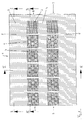
- the sealing element shown in a plan view in Figure 1 consists of a strip 1 made of a plastically deformable material, in particular a lead foil tape. in the 1 area of the finished sealing element can be seen, while from the right Different manufacturing stages are recognizable. On the far right in Fig. 1, the sealing element consists only of a uniformly pleated material. The The pitch and the depth of the pleating depend on how big the change in length or material spread during use.
- the sealing element shown here is designed as a ridge or ridge ventilation element and can basically in a middle section 4, a ventilation strip 9 and pleated longitudinal edge area 2 can be divided. It is with respect to the central longitudinal axis constructed symmetrically.
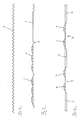
- the longitudinal edge portion 2 remains pleated, as well emerges from Figure 2.
- the material changes in the manufacturing process can in Figure 1 and in Figure 3 viewed from right to left.
- the starting material in the vent strip 9 initially had a pleated one Shape (see right outer edge in Figures 1 and 3).
- an embossing tool the formation of the flat area 3 in the vent strip 9.
- a flat section 3 is formed, which has a material thickness is thicker than the surrounding pleated areas.
- the flat area 3 is on its Roughened surfaces, because the embossing tool used is one Has structure. This ensures that the material slips when Forming did not take place.
- the flat areas 3 are embossed so that they form a vent strip 9 divided into sections. Between two flat ones Areas 3 are each a non-deformed pleated area, the one Water drainage channel 5 forms.
- vent strip 9 according to the invention can also be formed continuously without interruptions.
- the raised areas are in the flat areas 3 Water protection edges 6 embossed.
- these water protection edges are in the middle To see part. Due to the increased wall thickness in the flat area 3 can here very stable water protection edges 6 are embossed.
- the ventilation holes are then centered in the protruding water protection edges 6 introduced, for example by punching or Punch out.
- the ventilation holes are in FIGS. 1 and 3 with the reference number 7 Mistake. In the alternative, they are marked by short dashes.
- the manufacture of the invention Sealing element ended.
- the ventilation strip still visible on the left in FIG. 1 9 ventilation areas lying on the same shape as the one on the left Section shown in the outer edge in Figure 3. Due to its flat and strong material Structure in the vent strip 9, the sealing element thus formed offers an excellent Water resistance and can be optimally bent and laid.
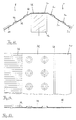
- FIG. 4 shows the cross section IV - IV in FIG. 1. That as a ridge or ridge ventilation element trained sealing element has a central portion 4, two on this subsequent ventilation strips 9 with ventilation holes 7 and two in turn thereon subsequent pleated longitudinal edge sections 2.
- the longitudinal edge sections form as can also be seen in particular in FIG. 5, in the valleys 11 of roofing slabs 10 when the sealing element is installed in a roof structure. You enlarge here their surface and seal the space below the ridge batten 12.
- the in Figure 5 in Roof element according to the invention shown laid, lies below the ridge pan 16 on the ridge batten 12, with its middle section 4. Extend on both sides then the vent strips away from the central section 4.
- vent strips are the flat areas 3 reinforced by forming in the material, into which the water protection edges 6 are embossed, which have the ventilation openings 7. Thereby, that the water protection edges 6 protrude upwards may run onto the sealing element water coming down around the vent holes, the water resistance is ensured.
- the pleated longitudinal edge sections 2, which are sealing in the valleys 11 of the roofing tiles 10 lie. The sealing element accordingly provides ventilation but also a seal securely.
- FIG. 6 shows a further embodiment of a sealing element according to the invention, that is designed as a ridge or ridge ventilation element, shown.
- the one shown in Figure 6 Sealing element is constructed in the same way as that shown in FIG. 1 with the exception that the longitudinal edge sections an outer edge with double wall thickness exhibit. This outer edge is provided with the reference number 8 in FIG.
- FIG. 7 shows schematically how such an area is manufactured. Left is too see that this area is folded from an upper section 8o like a lower one Section 8u exists. The lower section 8u will abut the upper section 8o bent and folded in the unpleated state, so that the one shown on the right in FIG Condition occurs. The outer edge 8 of the strip now has a double one Wall thickness and is therefore correspondingly heavier.
- Figure 8 shows the section VIII - VIII in Figure 6, ie a section through a complete manufactured sealing element according to this second embodiment. It is also recognizable here that the pleated edge part 2 has twice the wall thickness on its outer edge 8, which arises from the lower section 8u, which folds onto the upper section 8o has been. During the pleating process, these two areas were inseparable, so that there is no fear of detachment. The outer edge 8 is now so heavy that it is after forming on an uneven surface, for example on the valleys of Roof covering panels can no longer lift off due to wind. The tightness is ensured.
- FIGS. 9 and 10 finally show the fan according to the embodiment according to FIG 6 when installed in a roof truss. It is particularly evident here that the Areas 8 with twice the wall thickness lie sealingly on the roof tiles 10 and adapt optimally there.
- the ridge pan lies in the left-hand representation according to FIG 16 with its lower end 14 on the outer edge 8 of the sealing element and thus additionally ensures that the outer edge is lifted, for example by wind is prevented.
- Such an embodiment is very easy to achieve in that the Ridge slat 12 is lowered.
- This system does not have any for roof ventilation either Disadvantages, since sufficient can be vented through the roof tile valleys, where one Air duct forms.
- FIG. 10 shows another installation situation in which the lower end 15 of the ridge pan 16 hovers over the roof tile 10, in such a way that it reaches over the outer edge 8.
- the sealing element can advantageously be laid invisibly become.
- the sealing element according to FIG. 1 can, of course, also be shown on both Species are relocated.
- FIG. 11 shows a further embodiment of an inventive device in a sectional view Sealing element, namely a two-piece sealing element.
- the sealing element consists of the two left and right half-strips l and r and is again laid on a ridge batten 12.
- the left half-strip 1 lies with its middle section 4l directly on the ridge slat, and the flat section is in turn connected to the middle section 4l Area 3l with the water protection edges 6l and the ventilation holes 7l and thereupon the pleated longitudinal edge area 3l.
- the middle section 4r of the right half-strip r Also on the ridge batten and above the middle section 4l of the left half-strip l lies the middle section 4r of the right half-strip r.
- the right half-strip r also knows again the flat area 3r with the water protection edges 6r and the ventilation holes 7r and the pleated longitudinal edge area 3r.
- FIG. 11 So here is in Figures 11 to 13, the two-piece embodiment in the connected, shown overlapped state in the middle area.
- the middle regions 4l and 4r were also flattened after the pleating in order to overlapping connection, for example by nailing both middle sections 4l and 4r to be able to produce advantageously on the ridge batten.
- the Middle areas 4l and 4r can basically also remain pleated. It overlapped
- the state of the two half-strips l and r can be seen in plan view in FIG.
- the middle section 4r covers the middle section 4l almost completely.
- Left of the middle sections 4l and 4r is again the flat area 3l and the pleated one To see longitudinal edge section 2l, the function of which has already been described previously.
- the FIG. 13 again shows a cross section through the left half-strip 1 with the central section 4l, the flat section 3l and the pleated longitudinal edge section 2l.
Landscapes
- Engineering & Computer Science (AREA)
- Architecture (AREA)
- Civil Engineering (AREA)
- Structural Engineering (AREA)
- Roof Covering Using Slabs Or Stiff Sheets (AREA)
- Sealing Devices (AREA)
- Piezo-Electric Or Mechanical Vibrators, Or Delay Or Filter Circuits (AREA)
- Glass Compositions (AREA)
- Lining Or Joining Of Plastics Or The Like (AREA)
- Encapsulation Of And Coatings For Semiconductor Or Solid State Devices (AREA)
- Liquid Crystal (AREA)
- Measurement Of Radiation (AREA)
- Burglar Alarm Systems (AREA)
Abstract
Description
- Fig. 1
- eine Draufsicht auf ein Dichtungselement, in der die verschiedenen Fertigungsschritte abfolgend erkennbar sind;
- Fig. 2
- einen Schnitt entlang der Linie II - II in Fig. 1;
- Fig. 3
- einen Schnitt entlang der Linie III - III der Fig. 1;
- Fig. 4
- einen Schnitt entlang der Linie IV - IV in Fig. 1;
- Fig. 5
- einen Querschnitt durch einen Dachstuhl mit einem auf einer Firstlatte verlegten erfindungsgemäßen Dichtungselement;
- Fig. 6
- eine Draufsicht auf ein erfindungsgemäßes Dichtungselement in verschiedenen Fertigungsstufen gemäß einer zweiten Ausführungsform der Erfindung;
- Fig. 7
- einen Schnitt entlang der Linie VII - VII in Fig. 6;
- Fig. 8
- einen Schnitt entlang der Linie VIII - VIII in Fig. 6;
- Fig. 9 und Fig. 10
- verschiedene Einbausituationen für ein Dichtungselement nach Fig. 6;
- Fig. 11
- eine Schnittansicht eines zweitstückigen Dichtungselements auf einer Firstlatte;
- Fig. 12
- eine Draufsicht auf den linken Abschnitt des Dichtungselements in Figur 11; und
- Fig. 13
- eine Schnittansicht eines einzelnen Halbstreifens eines zweistückigen Dichtungselements.
Claims (13)
- Verfahren zur Herstellung eines Dichtungselements bei demein Streifen (1) aus einem plastisch verformbaren Material im wesentlichen ganzflächig mit einer mäanderförmigen, insbesondere einer wellen-, zickzack- oder stufenförmigen Plissierung versehen wird; undim Abstand zu den Längsrändern des plissierten Streifens (1) durch Umformen der Plissierung mindestens ein flacher Bereich (3) auf dem Streifen (1) ausgebildet wird.
- Verfahren nach Anspruch 1, bei dem der flache Bereich (3) streifenförmig in Längsrichtung des Elements, insbesondere durchgehend über die Streifenlänge ausgebildet wird.
- Verfahren nach Anspruch 1 oder 2, bei dem der flache Bereich (3) abschittsweise über die Streifenlänge ausgebildet wird, wobei insbesondere zwischen den Flachbereichsabschnitten Wasserablaufkanäle (5) entstehen.
- Verfahren nach einem der Ansprüche 1 bis 3, bei dem der flache Bereich (3) durch das Zusammendrücken der Plissierung, insbesondere durch Falten, Stauchen oder Prägen ausgebildet wird, wobei der flache Bereich (3) beim Umformen bevorzugt eine größere Wandstärke erhält als die plissiert verbleibenden Abschnitte, insbesondere eine etwa 1,5 bis 2,5 mal so große Wandstärke.
- Verfahren nach einem der Ansprüche 1 bis 4, bei dem der Streifen (1) an seinen beiden Längstandabschnitten und im Mittelabschnitt plissiert verbleibt, und der flache Bereich in einem Abschnitt (9) zwischen den Längsrandabschnitten (2) und dem Mittelabschnitt (4) ausgebildet wird, oder bei dem der Streifen an seinen beiden Längsrandabschnitten (2) plissiert verbleibt und flache Bereiche im Mittelabschnitt (4) sowie in einem Abschnitt (9) zwischen den Längsrandabschnitten und dem Mittelabschnitt (4) ausgebildet werden.
- Verfahren nach einem der Ansprüche 1 bis 5, bei dem in den Mittelabschnitt mindestens eine Nut zur Aufnahme von Befestigungselementen eingebracht wird, bzw. bei dem mittig im Mittelabschnitt (4), insbesondere mechanisch, eine Mittellinienmarkierung angebracht wird.
- Verfahren nach einem der Ansprüche 1 bis 6, bei dem das Werkzeug zum Umformen bzw. Zusammendrücken der Plissierung, insbesondere zum Falten, Stauchen oder Prägen eine strukturierte, insbesondere rautierte oder geriffelte Oberfläche hat.
- Verfahren nach einem der Ansprüche 1 bis 7, mit einem oder mehreren der folgenden MerkmaleEntlüftungsöffnungen (7) werden in den flachen Bereich eingebracht, die insbesondere von umlaufenden erhabenen Wasserschutzkanten (6) umgeben sind;der Streifen (1) besteht aus einem leicht plissierbaren, plastisch verformbaren Material, insbesondere aus Blei, vorzugsweise aus mit Reinzinn beschichtetem Blei, aus Aluminium, Kupfer oder Zinn, und er wird bevorzugt farbbeschichtet;das Dichtungselement wird als rollbares Endloselement ausgebildet;an den Unterseiten der Längsrandabschnitte (2) werden Klebeschnüre angebracht.die Längsrandabschnitte (2) des Streifens (1) werden vor dem Plissieren umgefalzt, so daß am Außenrand ein Bereich mit doppelter Wandstärke (8) entsteht.
- Verfahren zur Herstellung eines Dichtungselements, insbesondere nach einem der Ansprüche 1 bis 8, bei dem der Steifen zweistückig mit zwei Halbstreifen (l, r) ausgebildet wird, wobei beide Halbstreifen (l, r) im wesentlichen ganzflächig plissiert werden, jeweils im Abstand zu den Längsrändernjedes plissierten Halbstreifens (l, r) durch Umformen der Plissierung ein flacher Bereich (3l, 3r) auf den Halbstreifen (l, r) ausgebildet wird und die Halbstreifen dann, insbesondere überlappend, an jeweils einem ihrer Randbereiche (4l, 4r) verbunden werden.
- Verfahren nach Anspruch 9, bei dem die Verbindungsrandbereiche (4l, 4r) vor der Verbindung zu flachen Bereichen umgeformt werden.
- Verfahren nach Anspruch 9, bei dem die Verbindungsrandbereiche (4l, 4r) plissiert verbleiben.
- Dichtungselement bestehend aus einem Streifen (1) aus einem plastisch verformbaren Material das mit einer mäanderförmigen, insbesondere einer wellen-, zickzack- oder stufenförmigen Plissierung versehen ist, dadurch gekennzeichnet, daß auf dem plissierten Steifen (1) im Abstand zu den Längsrändern des Streifens (1) mindestens ein flacher Bereich (3) durch Umformen der Plissierung ausgebildet ist.
- Dichtungselement nach Anspruch 12, dadurch gekennzeichnet, daß es eines oder mehrere der gemäß den Ansprüchen 1 bis 11 ausgebildeten Merkmale aufweist.
Applications Claiming Priority (2)
| Application Number | Priority Date | Filing Date | Title |
|---|---|---|---|
| DE19833256 | 1998-07-23 | ||
| DE19833256A DE19833256C2 (de) | 1998-07-23 | 1998-07-23 | Dichtungselement und Verfahren zur Herstellung desselben |
Publications (3)
| Publication Number | Publication Date |
|---|---|
| EP0980725A2 true EP0980725A2 (de) | 2000-02-23 |
| EP0980725A3 EP0980725A3 (de) | 2000-03-29 |
| EP0980725B1 EP0980725B1 (de) | 2003-09-10 |
Family
ID=7875109
Family Applications (1)
| Application Number | Title | Priority Date | Filing Date |
|---|---|---|---|
| EP99113698A Expired - Lifetime EP0980725B1 (de) | 1998-07-23 | 1999-07-16 | Dichtungselement und Verfahren zur Herstellung desselben |
Country Status (6)
| Country | Link |
|---|---|
| EP (1) | EP0980725B1 (de) |
| AT (1) | ATE249296T1 (de) |
| DE (2) | DE19833256C2 (de) |
| DK (1) | DK0980725T3 (de) |
| NO (1) | NO993579D0 (de) |
| PL (1) | PL334207A1 (de) |
Cited By (1)
| Publication number | Priority date | Publication date | Assignee | Title |
|---|---|---|---|---|
| CN103276856A (zh) * | 2013-04-28 | 2013-09-04 | 广西南南铝箔有限责任公司 | 用于屋顶的铝裙的生产工艺及设备 |
Family Cites Families (13)
| Publication number | Priority date | Publication date | Assignee | Title |
|---|---|---|---|---|
| GB1546097A (en) * | 1975-08-20 | 1979-05-16 | Atomic Energy Authority Uk | Fabricating catalyst bodies |
| DE8701605U1 (de) * | 1987-02-03 | 1987-05-07 | Karl Braun Gmbh, 7315 Weilheim | Bleischürze für Eindeckrahmen von Dachfenstern |
| DE3703886A1 (de) * | 1987-02-09 | 1988-08-18 | Alfons Knoche | Laengsgeteiltes dichtungselement zur abdichtung der firste von ziegelgedeckten satteldaechern |
| DK166833B1 (da) * | 1989-10-12 | 1993-07-19 | Rasmussen Kann Ind As | Taginddaekningsmateriale |
| US5179770A (en) * | 1990-01-26 | 1993-01-19 | Lcoa Laminating Company Of America | Machine and method for fabricating a sheet metal structure having a corrugated core |
| DE4333247A1 (de) * | 1993-09-30 | 1995-04-06 | Braas Gmbh | Plastisch verformbare Abdeckung |
| DE9405203U1 (de) * | 1994-03-26 | 1995-04-27 | Gehring Manfred Dr | Rollbarer Dichtungsstreifen für eine First- oder Gratabdeckung |
| DE4414211A1 (de) * | 1994-04-23 | 1995-10-26 | Roland Schmid Baukunststoffe G | Lüfterkappe und Verbindungselement zum Verbinden eines Schaumstoffelementes mit dem Trägerelement einer derartigen Lüfterkappe |
| DE29501242U1 (de) * | 1995-01-27 | 1995-03-16 | Gehring Manfred Dr | Rollbarer Dichtungsstreifen für eine First- und/oder Gratabdeckung |
| DE19537266C2 (de) * | 1995-10-06 | 2002-11-07 | Kurt Schade Gmbh & Co Ing | Dichtungsstreifen für eine First- oder Gratabdeckung |
| DE29604146U1 (de) * | 1996-03-06 | 1996-04-18 | Gehring Manfred Dr | Dichtungsstreifen für eine First- und/oder Gratabdeckung |
| DE19747217C1 (de) * | 1997-10-25 | 1999-04-15 | Mage Gmbh | First- oder Gratbelüftungselement |
| DE19810434C1 (de) * | 1998-03-11 | 1999-06-02 | Peter Wirz | Streifenförmige Materialbahn für eine First- oder Gratabdeckung sowie Verfahren und Vorrichtung zur Herstellung derselben |
-
1998
- 1998-07-23 DE DE19833256A patent/DE19833256C2/de not_active Expired - Fee Related
-
1999
- 1999-07-06 PL PL99334207A patent/PL334207A1/xx unknown
- 1999-07-16 DE DE59906930T patent/DE59906930D1/de not_active Expired - Fee Related
- 1999-07-16 DK DK99113698T patent/DK0980725T3/da active
- 1999-07-16 AT AT99113698T patent/ATE249296T1/de not_active IP Right Cessation
- 1999-07-16 EP EP99113698A patent/EP0980725B1/de not_active Expired - Lifetime
- 1999-07-22 NO NO993579A patent/NO993579D0/no unknown
Cited By (2)
| Publication number | Priority date | Publication date | Assignee | Title |
|---|---|---|---|---|
| CN103276856A (zh) * | 2013-04-28 | 2013-09-04 | 广西南南铝箔有限责任公司 | 用于屋顶的铝裙的生产工艺及设备 |
| CN103276856B (zh) * | 2013-04-28 | 2015-09-16 | 广西南南铝箔有限责任公司 | 用于屋顶的铝裙的生产工艺及设备 |
Also Published As
| Publication number | Publication date |
|---|---|
| DK0980725T3 (da) | 2004-01-26 |
| ATE249296T1 (de) | 2003-09-15 |
| DE59906930D1 (de) | 2003-10-16 |
| DE19833256C2 (de) | 2002-07-11 |
| DE19833256A1 (de) | 2001-07-26 |
| EP0980725A3 (de) | 2000-03-29 |
| EP0980725B1 (de) | 2003-09-10 |
| NO993579D0 (no) | 1999-07-22 |
| PL334207A1 (en) | 2000-01-31 |
Similar Documents
| Publication | Publication Date | Title |
|---|---|---|
| EP0835356B1 (de) | Plastisch von hand verformbares abdeckmaterial | |
| DE19537266C2 (de) | Dichtungsstreifen für eine First- oder Gratabdeckung | |
| EP0724048B1 (de) | Rollbarer Dichtungsstreifen für eine First- und/oder Gratabdeckung | |
| DE19606843A1 (de) | Aufrollbares First- und Gratbelüftungselement und Verfahren zu dessen Herstellung | |
| EP0980725B1 (de) | Dichtungselement und Verfahren zur Herstellung desselben | |
| EP0911459B1 (de) | First- oder Gratbelüftungselement | |
| DE2642999C2 (de) | Selbstspannende Wandbekleidungsplatte | |
| EP1152099B1 (de) | Dichtungsband für eine First- oder Gratabdeckung | |
| DE29604146U1 (de) | Dichtungsstreifen für eine First- und/oder Gratabdeckung | |
| EP0863271B1 (de) | Abdeckung für den Kehlbereich eines Daches | |
| EP1949980B1 (de) | Verfahren und Vorrichtung zum Herstellen eines gekreppten Materials für Anschlüsse und Übergänge an Gebäuden | |
| EP2754832B1 (de) | Verfahren und Vorrichtung zum Einsetzen einer Scheibe in einen Rahmen | |
| EP1389659B1 (de) | Reinigungsvorrichtung zum Aufbringen auf eine dem Wetter ausgesetzte Oberfläche | |
| DE29522000U1 (de) | Dichtungsstreifen für eine First- oder Gratabdeckung | |
| EP1974834A2 (de) | Anschluss oder Abschlussband für Gebäude mit Sollknickstelle | |
| EP1508655B1 (de) | Streifenförmige Materialbahn für eine First- und/oder Gratabdeckung | |
| EP3569789B1 (de) | Lüftungsband für den first oder grat eines daches | |
| DE19841472C2 (de) | Belüftungselement mit angesetzten Seitenteilen | |
| EP0722527B1 (de) | Firstabdichtungsstreifen | |
| EP1030002B1 (de) | First- oder Gratenlüftungselement und Verfahren zu seiner Herstellung | |
| DE20313027U1 (de) | Streifenförmige Materialbahn für eine First- und/oder Gratabdeckung | |
| DE19912698A1 (de) | Vorrichtung und Verfahren zur Herstellung eines First- und Gratabdeckungsstreifens aus einem Streifen aus plastisch verformbaren Material | |
| EP0761903B1 (de) | Metall-Dachplatte | |
| DE20201197U1 (de) | Rollbarer First- und/oder Gratlüftungsstreifen | |
| DE29723782U1 (de) | First- oder Gratbelüftungselement |
Legal Events
| Date | Code | Title | Description |
|---|---|---|---|
| PUAI | Public reference made under article 153(3) epc to a published international application that has entered the european phase |
Free format text: ORIGINAL CODE: 0009012 |
|
| PUAL | Search report despatched |
Free format text: ORIGINAL CODE: 0009013 |
|
| AK | Designated contracting states |
Kind code of ref document: A2 Designated state(s): AT BE CH CY DE DK ES FI FR GB GR IE IT LI LU MC NL PT SE |
|
| AX | Request for extension of the european patent |
Free format text: AL;LT;LV;MK;RO;SI |
|
| AK | Designated contracting states |
Kind code of ref document: A3 Designated state(s): AT BE CH CY DE DK ES FI FR GB GR IE IT LI LU MC NL PT SE |
|
| AX | Request for extension of the european patent |
Free format text: AL;LT;LV;MK;RO;SI |
|
| 17P | Request for examination filed |
Effective date: 20000518 |
|
| AKX | Designation fees paid |
Free format text: AT BE CH CY DE DK ES FI FR GB GR IE IT LI LU MC NL PT SE |
|
| 17Q | First examination report despatched |
Effective date: 20020802 |
|
| RAP1 | Party data changed (applicant data changed or rights of an application transferred) |
Owner name: MBE MODERNE BEFESTIGUNGSELEMENTE GMBH |
|
| RIN1 | Information on inventor provided before grant (corrected) |
Inventor name: KNOCHE, ALFONS |
|
| GRAH | Despatch of communication of intention to grant a patent |
Free format text: ORIGINAL CODE: EPIDOS IGRA |
|
| GRAS | Grant fee paid |
Free format text: ORIGINAL CODE: EPIDOSNIGR3 |
|
| GRAA | (expected) grant |
Free format text: ORIGINAL CODE: 0009210 |
|
| AK | Designated contracting states |
Kind code of ref document: B1 Designated state(s): AT BE CH CY DE DK ES FI FR GB GR IE IT LI LU MC NL PT SE |
|
| PG25 | Lapsed in a contracting state [announced via postgrant information from national office to epo] |
Ref country code: IT Free format text: LAPSE BECAUSE OF FAILURE TO SUBMIT A TRANSLATION OF THE DESCRIPTION OR TO PAY THE FEE WITHIN THE PRESCRIBED TIME-LIMIT;WARNING: LAPSES OF ITALIAN PATENTS WITH EFFECTIVE DATE BEFORE 2007 MAY HAVE OCCURRED AT ANY TIME BEFORE 2007. THE CORRECT EFFECTIVE DATE MAY BE DIFFERENT FROM THE ONE RECORDED. Effective date: 20030910 Ref country code: IE Free format text: LAPSE BECAUSE OF FAILURE TO SUBMIT A TRANSLATION OF THE DESCRIPTION OR TO PAY THE FEE WITHIN THE PRESCRIBED TIME-LIMIT Effective date: 20030910 Ref country code: GB Free format text: LAPSE BECAUSE OF FAILURE TO SUBMIT A TRANSLATION OF THE DESCRIPTION OR TO PAY THE FEE WITHIN THE PRESCRIBED TIME-LIMIT Effective date: 20030910 Ref country code: FI Free format text: LAPSE BECAUSE OF FAILURE TO SUBMIT A TRANSLATION OF THE DESCRIPTION OR TO PAY THE FEE WITHIN THE PRESCRIBED TIME-LIMIT Effective date: 20030910 Ref country code: CY Free format text: LAPSE BECAUSE OF FAILURE TO SUBMIT A TRANSLATION OF THE DESCRIPTION OR TO PAY THE FEE WITHIN THE PRESCRIBED TIME-LIMIT Effective date: 20030910 |
|
| REG | Reference to a national code |
Ref country code: GB Ref legal event code: FG4D Free format text: NOT ENGLISH |
|
| REG | Reference to a national code |
Ref country code: CH Ref legal event code: NV Representative=s name: RIEDERER HASLER & PARTNER PATENTANWAELTE AG Ref country code: CH Ref legal event code: EP |
|
| REF | Corresponds to: |
Ref document number: 59906930 Country of ref document: DE Date of ref document: 20031016 Kind code of ref document: P |
|
| REG | Reference to a national code |
Ref country code: IE Ref legal event code: FG4D Free format text: GERMAN |
|
| PG25 | Lapsed in a contracting state [announced via postgrant information from national office to epo] |
Ref country code: SE Free format text: LAPSE BECAUSE OF FAILURE TO SUBMIT A TRANSLATION OF THE DESCRIPTION OR TO PAY THE FEE WITHIN THE PRESCRIBED TIME-LIMIT Effective date: 20031210 Ref country code: GR Free format text: LAPSE BECAUSE OF FAILURE TO SUBMIT A TRANSLATION OF THE DESCRIPTION OR TO PAY THE FEE WITHIN THE PRESCRIBED TIME-LIMIT Effective date: 20031210 |
|
| PG25 | Lapsed in a contracting state [announced via postgrant information from national office to epo] |
Ref country code: PT Free format text: LAPSE BECAUSE OF FAILURE TO SUBMIT A TRANSLATION OF THE DESCRIPTION OR TO PAY THE FEE WITHIN THE PRESCRIBED TIME-LIMIT Effective date: 20031218 |
|
| PG25 | Lapsed in a contracting state [announced via postgrant information from national office to epo] |
Ref country code: ES Free format text: LAPSE BECAUSE OF FAILURE TO SUBMIT A TRANSLATION OF THE DESCRIPTION OR TO PAY THE FEE WITHIN THE PRESCRIBED TIME-LIMIT Effective date: 20031221 |
|
| REG | Reference to a national code |
Ref country code: DK Ref legal event code: T3 |
|
| GBV | Gb: ep patent (uk) treated as always having been void in accordance with gb section 77(7)/1977 [no translation filed] |
Effective date: 20030910 |
|
| REG | Reference to a national code |
Ref country code: IE Ref legal event code: FD4D |
|
| ET | Fr: translation filed | ||
| PG25 | Lapsed in a contracting state [announced via postgrant information from national office to epo] |
Ref country code: LU Free format text: LAPSE BECAUSE OF NON-PAYMENT OF DUE FEES Effective date: 20040716 |
|
| PLBE | No opposition filed within time limit |
Free format text: ORIGINAL CODE: 0009261 |
|
| STAA | Information on the status of an ep patent application or granted ep patent |
Free format text: STATUS: NO OPPOSITION FILED WITHIN TIME LIMIT |
|
| PG25 | Lapsed in a contracting state [announced via postgrant information from national office to epo] |
Ref country code: MC Free format text: LAPSE BECAUSE OF NON-PAYMENT OF DUE FEES Effective date: 20040731 |
|
| 26N | No opposition filed |
Effective date: 20040614 |
|
| PGFP | Annual fee paid to national office [announced via postgrant information from national office to epo] |
Ref country code: NL Payment date: 20060714 Year of fee payment: 8 Ref country code: FR Payment date: 20060714 Year of fee payment: 8 Ref country code: DE Payment date: 20060714 Year of fee payment: 8 Ref country code: CH Payment date: 20060714 Year of fee payment: 8 Ref country code: AT Payment date: 20060714 Year of fee payment: 8 |
|
| PGFP | Annual fee paid to national office [announced via postgrant information from national office to epo] |
Ref country code: BE Payment date: 20060822 Year of fee payment: 8 |
|
| BERE | Be: lapsed |
Owner name: MODERNE BEFESTIGUNGSELEMENTE G.M.B.H. *MBE Effective date: 20070731 |
|
| REG | Reference to a national code |
Ref country code: CH Ref legal event code: PL |
|
| REG | Reference to a national code |
Ref country code: DK Ref legal event code: EBP |
|
| NLV4 | Nl: lapsed or anulled due to non-payment of the annual fee |
Effective date: 20080201 |
|
| PG25 | Lapsed in a contracting state [announced via postgrant information from national office to epo] |
Ref country code: NL Free format text: LAPSE BECAUSE OF NON-PAYMENT OF DUE FEES Effective date: 20080201 Ref country code: LI Free format text: LAPSE BECAUSE OF NON-PAYMENT OF DUE FEES Effective date: 20070731 Ref country code: DE Free format text: LAPSE BECAUSE OF NON-PAYMENT OF DUE FEES Effective date: 20080201 Ref country code: CH Free format text: LAPSE BECAUSE OF NON-PAYMENT OF DUE FEES Effective date: 20070731 |
|
| PGFP | Annual fee paid to national office [announced via postgrant information from national office to epo] |
Ref country code: DK Payment date: 20060714 Year of fee payment: 8 |
|
| REG | Reference to a national code |
Ref country code: FR Ref legal event code: ST Effective date: 20080331 |
|
| PG25 | Lapsed in a contracting state [announced via postgrant information from national office to epo] |
Ref country code: AT Free format text: LAPSE BECAUSE OF NON-PAYMENT OF DUE FEES Effective date: 20070716 |
|
| PG25 | Lapsed in a contracting state [announced via postgrant information from national office to epo] |
Ref country code: DK Free format text: LAPSE BECAUSE OF NON-PAYMENT OF DUE FEES Effective date: 20070731 |
|
| PG25 | Lapsed in a contracting state [announced via postgrant information from national office to epo] |
Ref country code: BE Free format text: LAPSE BECAUSE OF NON-PAYMENT OF DUE FEES Effective date: 20070731 |
|
| PG25 | Lapsed in a contracting state [announced via postgrant information from national office to epo] |
Ref country code: FR Free format text: LAPSE BECAUSE OF NON-PAYMENT OF DUE FEES Effective date: 20070731 |