EP0980734A1 - Selbstumkehrendes Gewindeschneidgerät mit Dämpfungseinrichtung - Google Patents
Selbstumkehrendes Gewindeschneidgerät mit Dämpfungseinrichtung Download PDFInfo
- Publication number
- EP0980734A1 EP0980734A1 EP98306671A EP98306671A EP0980734A1 EP 0980734 A1 EP0980734 A1 EP 0980734A1 EP 98306671 A EP98306671 A EP 98306671A EP 98306671 A EP98306671 A EP 98306671A EP 0980734 A1 EP0980734 A1 EP 0980734A1
- Authority
- EP
- European Patent Office
- Prior art keywords
- drive means
- set forth
- tap
- tap spindle
- spindle
- Prior art date
- Legal status (The legal status is an assumption and is not a legal conclusion. Google has not performed a legal analysis and makes no representation as to the accuracy of the status listed.)
- Withdrawn
Links
Images


Classifications
-
- B—PERFORMING OPERATIONS; TRANSPORTING
- B23—MACHINE TOOLS; METAL-WORKING NOT OTHERWISE PROVIDED FOR
- B23G—THREAD CUTTING; WORKING OF SCREWS, BOLT HEADS, OR NUTS, IN CONJUNCTION THEREWITH
- B23G1/00—Thread cutting; Automatic machines specially designed therefor
- B23G1/44—Equipment or accessories specially designed for machines or devices for thread cutting
- B23G1/46—Equipment or accessories specially designed for machines or devices for thread cutting for holding the threading tools
- B23G1/465—Equipment or accessories specially designed for machines or devices for thread cutting for holding the threading tools comprising arrangements for reversing the rotation of the tool
Definitions
- the invention relates and pertains to tapping attachments, i.e. tools which carry taps for threading holes and are driven by a driving machine or power center and to reduction of stress and wear for components thereof.
- the tap threads a hole being tapped in the workpiece and thereby screws itself into the hole.
- relative axial movement results between the tap holding spindle and the driver members such that the forward drive member becomes disengaged from the tap spindle which at this point is held relatively stationary due to the fact that the tap has become fastened to the workpiece.
- the reverse drive member becomes engaged with the tap holding spindle, causing reverse rotation thereof and thereby unscrewing the tap from the hole.
- Self-reversing tapping attachments have particular parts which due to the very nature of self-reversing suffer greater stress and wear than other parts, especially in connection with modern ultra-high-speed tapping. Such stress and wear occur primarily in the transition between forward and reverse, wherein the balls in the coupling on the tap holding spindle proceed through a limited neutral zone between engagement with splines on the forward drive element and splines on the reverse drive element.
- a self-reversing tapping attachment comprises: tap holding spindle means; forward drive means and reverse drive means for engaging with the tap holding spindle means to impart forward and reverse rotation, respectively, thereto; and shock absorbing means associated with at least one of said forward drive means and said reverse drive means for providing cushioned engagement between said drive means and said tap holding spindle means.
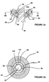
- a tapping attachment 10 is coupleable through a shank 12 to a source of rotational drive in the form of a driving machine (not shown).
- a stem 14 is disposed in and extends from a closure 15 positioned adjacent a housing 16 of the tapping attachment 10 and is connectable in conventional fashion to the driving machine to provide restraint against rotation of the housing 16 of tapping attachment 10 when connected to the driving machine and to permit rotation under particular circumstances when not so connected.
- Housing 16 defines a central bore 17 for receiving a drive spindle member 18.
- Drive spindle member 18 partially extends outwardly of housing 16. At its upper end, spindle member 18 extends into and is engaged with the member 12 for engagement with the driving machine.
- drive spindle member 18 includes a mount 20 having an insert 22, defining a central bore 24.
- a coolant tube 26 connects to central bore 24 and forms a conduit for passage of coolant therethrough for the purpose of cooling the tap and clearing debris in the form of cuttings and the like from the work piece; a fluid inlet 25 connects to coolant tube 26.
- a tap is carried and held by a collet (not shown) in a collet space 28 secured by a chuck nut 29 on a tap spindle member 30 fastened to a return spring 32.
- Drive spindle member 18 at an upper portion thereof extends outwardly of housing 16 as noted above and comprises a lower end portion 34 within housing 16.
- Gear drive 40 comprises an upper gear 42, a lower gear 44, and a plurality of planet gears 48.
- a planet gear carrier 49 is mounted in housing 16. Planet gears 48 are mounted in planet gear carrier 49 and are positioned to be engageable with gears 42,44.
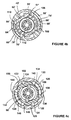
- a forward drive member 50 of generally annular configuration, defines a central bore 52.
- Upper gear 42 carries on its radially inward wall at least one drive spline member 54.
- Forward drive member 50 is engageable with upper gear 42.
- a reverse drive member 51 is engageable with lower gear 44.
- Forward drive member 50 and reverse drive member 51 differ only in their dimension along the radial direction; thus, for brevity and clarity only one of the drive members, forward drive member 50, need be described explicitly herein.
- Spline 54 on upper gear 42 comprises a pair of symmetrical generally arcuate contact areas 55, joined by a generally arcuate intermediate region 57.
- Forward drive member 50 defines at least one, shown in the depicted embodiment as two, splines 100 for engaging upper gear 42.
- Upper gear 42 includes at least one, shown as two, inner recesses 59 for receiving splines 100 of forward drive member 50.
- drive member 50 includes at least one (depicted herein as two) carriers 58,60 for shock absorbers 62,64, respectively.
- Shock absorbers 62, 64 are identical and are described accordingly herein.
- Shock absorber 62 comprises a pair of compression spring members 66, 68, fastened at end pieces in the form of caps 70, 72.
- a torque transmitting member in the form of a ball 74 is disposed between and in contact with springs 66, 68.
- spring members 76, 78, end pieces in the form of caps 80, 82 and torque member 84 correspond to parts 66, 68, 70, 72 and 74, respectively, at carrier 58.
- shock absorbers may be attached to other members than the forward and reverse drive members 50,51.
- Carriers 58, 60 are positioned such as to be contactable by adjacent drive splines 54.
- the length of shock absorber movement is substantially equal to one-quarter inch (1/4"), though of course other particular dimensions may be employed in accordance with the invention.
- a single spring member without a ball may be employed; such an arrangement would call for a spring with greater stiffness to perform the same functions as the device depicted in Fig. 4a.
- End pieces 70, 72 comprise bases 71, 73, respectively, and stems 75, 77 respectively.
- Bases 71, 73 have contours such that they conform substantially to the contours of the ends of carriers 58, 60, respectively.
- Parts 71, 73, 75, 77 on carrier 58 correspond to the same parts 81, 83, 85, 87 on carrier 60.
- forward drive member 50 is depicted in driving relationship with a tap spindle drive sleeve 90.
- Fig. 4b Depicted in Fig. 4b is an alternative embodiment of the invention.
- parts 42', 50', 52', 54', 55', 57', 58', 60', 62', 64', 66', 68', 74', 76', 78' and 84' correspond to their unprimed numbered counterparts depicted in Fig. 4a.
- End pieces, 106, 108 in carrier 58' and end pieces 110, 112 in carrier 60' comprise spherical balls.
- the balls depicted in Fig. 4b may be employed in place of the caps depicted in Fig. 4a.
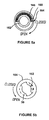
- Fig. 4c Depicted in Fig. 4c is a further alternative embodiment of the invention. As depicted in Fig. 4c, driving is accomplished through a ball drive as opposed to the ball/spline configuration described in connection with Figs. 4a,4b.
- Upper gear 120 is of annular configuration and includes a ball race 122 including at least two drive balls 124.
- a drive member 125 is engageable as the driven part with upper gear 120.
- Shock absorber 130 is of the same type as depicted in Fig. 4b, with a pair of compression spring members 134,136 and a torque-transmitting ball member disposed in contact with spring members 134,136 and end piece balls 138,140.
- Shock absorber 132 comprises parts 144,146,148,150 corresponding to parts 134,136,138,140.
- Drive sleeve 90 functions in similar manner to drive sleeve 90 of the preferred embodiment.
- Drive sleeve 90 within housing 16 is generally cylindrical having a central bore 92 and defines at its periphery at least one slot 94 for accommodation and movement therein of drive balls 98.
- Drive sleeve member 90 includes at least one drive spline 101 engageable with tap spindle member 30, which carries at least one drive pin 102.
- Slot 94 is preferably of generally ellipsoidal configuration.
- Drive spline 101, drive pin 102 and slot 94 are in accordance with the disclosure and claims in U.S. Patent No. 5,209,616 assigned to the assignee hereof and incorporated by reference herein. As disclosed in detail in Patent No. 5,209,616 the configuration and relations of the above-described parts tend to minimize wear and shock in operation.
- the tap is held in a holder in the form of a chuck 160, which is lockably mounted on tap spindle 30.
- the latter includes a pair of detents 162.
- Chuck 160 includes a locking collar 164 in which is mounted a locking spring 166 attached to locking pins 168 such that in the depicted configuration chuck 160 is held on tap spindle 30.
- This quick change arrangement is particularly useful in applications wherein tap spindles are composed of aluminum with chrome plating for purposes of decreasing weight and shock stress associated with the transition between forward and reverse.
- coolant tube 26 aligns with the tap which contains channels (not shown) for passage therethrough of coolant from tube 26.
- rotation is transmitted from the driving machine to forward drive member 50 and to reverse drive member 51 through gear means 40, planet gear 48, upper gear 42 (forward drive) and lower gear 44 (reverse drive).
- drive splines 54 of upper gear 42 drivingly engage with forward drive member 50.
- Drive member 50 is rotated in the forward direction and drivingly engages drive sleeve 90 which in turn drives tap spindle 30.
- Coolant is provided during tapping from the driving machine 12 via the conduit 26.
- the tapping attachment 10 is raised by the driving machine.
- the tap is embedded in the hole and removal is most conveniently accomplished by reversing the tap rotation.
- drive sleeve 90 briefly disengages from forward drive member 50 and after passing through a neutral zone engages reverse drive member 51, thereby causing reverse rotation of the spindle 30 enabling efficient withdrawal of the tap from the hole.
- Engagement between tap drive spindle 30 and the respective forward and reverse driver members 50,51 is through the shock absorbers 58,60 in forward drive and through identical parts (not shown) in reverse drive member 51.
- the shock absorbers 58,60 Upon initial contact in a transition among neutral forward and reverse, the shock absorbers 58,60 absorb angular momentum by compression of their respective spring members.
- the cushioning/shock absorption takes place over a length substantially equal to one-quarter inch (1/4"). Flexing of the spring members is augmented by the rotation of the ball members between them. After the initial impart, the drive elements come into positive engagement. It is believed that shock absorbers 58,60 lessen shock and stress not only at initial contact but continuingly during driving.
- the lock collar 164 attached to the lower end of spindle 30 is moved gradually and rotated until slots 162 in spindle 30 are exposed.
- Chuck 160 may then be installed and the collar 164 released, covering slots 162 and fastening chuck 160 in place. Removal is accomplished in reverse manner.
Landscapes
- Engineering & Computer Science (AREA)
- Mechanical Engineering (AREA)
- Gears, Cams (AREA)
Priority Applications (1)
| Application Number | Priority Date | Filing Date | Title |
|---|---|---|---|
| EP98306671A EP0980734A1 (de) | 1998-08-20 | 1998-08-20 | Selbstumkehrendes Gewindeschneidgerät mit Dämpfungseinrichtung |
Applications Claiming Priority (1)
| Application Number | Priority Date | Filing Date | Title |
|---|---|---|---|
| EP98306671A EP0980734A1 (de) | 1998-08-20 | 1998-08-20 | Selbstumkehrendes Gewindeschneidgerät mit Dämpfungseinrichtung |
Publications (1)
| Publication Number | Publication Date |
|---|---|
| EP0980734A1 true EP0980734A1 (de) | 2000-02-23 |
Family
ID=8235008
Family Applications (1)
| Application Number | Title | Priority Date | Filing Date |
|---|---|---|---|
| EP98306671A Withdrawn EP0980734A1 (de) | 1998-08-20 | 1998-08-20 | Selbstumkehrendes Gewindeschneidgerät mit Dämpfungseinrichtung |
Country Status (1)
| Country | Link |
|---|---|
| EP (1) | EP0980734A1 (de) |
Citations (3)
| Publication number | Priority date | Publication date | Assignee | Title |
|---|---|---|---|---|
| EP0509143A1 (de) * | 1991-04-17 | 1992-10-21 | OTTO BILZ Werkzeugfabrik GmbH & Co. | Gewindescheidapparat |
| US5203651A (en) * | 1989-03-30 | 1993-04-20 | Tapmatic Corporation | Tapping attachments |
| EP0677351A1 (de) * | 1994-03-28 | 1995-10-18 | Tapmatic Corporation | Demontierbares Gewindebohrgerät mit schnellwechselbaren und unterhaltbaren Teilen und Methode |
-
1998
- 1998-08-20 EP EP98306671A patent/EP0980734A1/de not_active Withdrawn
Patent Citations (3)
| Publication number | Priority date | Publication date | Assignee | Title |
|---|---|---|---|---|
| US5203651A (en) * | 1989-03-30 | 1993-04-20 | Tapmatic Corporation | Tapping attachments |
| EP0509143A1 (de) * | 1991-04-17 | 1992-10-21 | OTTO BILZ Werkzeugfabrik GmbH & Co. | Gewindescheidapparat |
| EP0677351A1 (de) * | 1994-03-28 | 1995-10-18 | Tapmatic Corporation | Demontierbares Gewindebohrgerät mit schnellwechselbaren und unterhaltbaren Teilen und Methode |
Similar Documents
| Publication | Publication Date | Title |
|---|---|---|
| US5865575A (en) | Self-reversing tapping attachment with shock absorption | |
| US6629697B1 (en) | Chuck apparatus | |
| US5992538A (en) | Impact tool driver | |
| EP0305616B1 (de) | Bearbeitungszentrum mit Fluidzuführeinrichtungitungszentrum | |
| US7455303B2 (en) | Chuck with internal nut | |
| GB2334910A (en) | Torque clutch in a drill/screwdriver | |
| US3999642A (en) | Clutching means adapted for use in tapping attachments | |
| WO1981002401A1 (en) | Power drawfinger system for machine tool spindle | |
| RU2649710C2 (ru) | Модульная режущая головка | |
| EP0072657B1 (de) | Zusatzvorrichtung zum Anbringen an einer Maschinenantriebsspindel | |
| US7070491B2 (en) | Machine tool with fluid actuated helical adjustment of abrasive elements | |
| US5064322A (en) | Joint for modular toolholder device of a tool machine for the working of metals and other | |
| JP3088836B2 (ja) | ねじ切り盤 | |
| EP0980734A1 (de) | Selbstumkehrendes Gewindeschneidgerät mit Dämpfungseinrichtung | |
| US4708538A (en) | Tapping head | |
| EP0520771B1 (de) | Verbesserter Antrieb für Gewindebohrgerät | |
| EP0677351B1 (de) | Demontierbares Gewindebohrgerät mit schnellwechselbaren und unterhaltbaren Teilen und Methode | |
| GB2162105A (en) | Tapper | |
| EP0618034B1 (de) | Gewindebohrvorrichtung zum radialen Gewindebohren | |
| US20060051170A1 (en) | Self-reversing tapping system | |
| WO1999010127A9 (en) | Improved parts and subassemblies for self-reversing tapping attachments | |
| SU1748964A1 (ru) | Самоцентрирующий токарный патрон | |
| SU814656A1 (ru) | Устройство дл очистки от стружкиОСЕВОгО иНСТРуМЕНТА | |
| CN201076916Y (zh) | 两级夹紧钻夹头 | |
| JPH0321882Y2 (de) |
Legal Events
| Date | Code | Title | Description |
|---|---|---|---|
| PUAI | Public reference made under article 153(3) epc to a published international application that has entered the european phase |
Free format text: ORIGINAL CODE: 0009012 |
|
| AK | Designated contracting states |
Kind code of ref document: A1 Designated state(s): DE FR GB IT |
|
| AX | Request for extension of the european patent |
Free format text: AL;LT;LV;MK;RO;SI |
|
| 17P | Request for examination filed |
Effective date: 20000325 |
|
| AKX | Designation fees paid |
Free format text: DE FR GB IT |
|
| 17Q | First examination report despatched |
Effective date: 20020612 |
|
| STAA | Information on the status of an ep patent application or granted ep patent |
Free format text: STATUS: THE APPLICATION IS DEEMED TO BE WITHDRAWN |
|
| 18D | Application deemed to be withdrawn |
Effective date: 20021023 |