EP0980743A1 - Tragbares kraftbetriebenes Werkzeug mit wärmeabsorbierendem Schild - Google Patents
Tragbares kraftbetriebenes Werkzeug mit wärmeabsorbierendem Schild Download PDFInfo
- Publication number
- EP0980743A1 EP0980743A1 EP99850125A EP99850125A EP0980743A1 EP 0980743 A1 EP0980743 A1 EP 0980743A1 EP 99850125 A EP99850125 A EP 99850125A EP 99850125 A EP99850125 A EP 99850125A EP 0980743 A1 EP0980743 A1 EP 0980743A1
- Authority
- EP
- European Patent Office
- Prior art keywords
- housing
- heat
- motor
- power tool
- stator
- Prior art date
- Legal status (The legal status is an assumption and is not a legal conclusion. Google has not performed a legal analysis and makes no representation as to the accuracy of the status listed.)
- Granted
Links
Images

Classifications
-
- B—PERFORMING OPERATIONS; TRANSPORTING
- B24—GRINDING; POLISHING
- B24B—MACHINES, DEVICES, OR PROCESSES FOR GRINDING OR POLISHING; DRESSING OR CONDITIONING OF ABRADING SURFACES; FEEDING OF GRINDING, POLISHING, OR LAPPING AGENTS
- B24B23/00—Portable grinding machines, e.g. hand-guided; Accessories therefor
- B24B23/02—Portable grinding machines, e.g. hand-guided; Accessories therefor with rotating grinding tools; Accessories therefor
- B24B23/028—Angle tools
-
- B—PERFORMING OPERATIONS; TRANSPORTING
- B24—GRINDING; POLISHING
- B24B—MACHINES, DEVICES, OR PROCESSES FOR GRINDING OR POLISHING; DRESSING OR CONDITIONING OF ABRADING SURFACES; FEEDING OF GRINDING, POLISHING, OR LAPPING AGENTS
- B24B47/00—Drives or gearings; Equipment therefor
- B24B47/10—Drives or gearings; Equipment therefor for rotating or reciprocating working-spindles carrying grinding wheels or workpieces
- B24B47/14—Drives or gearings; Equipment therefor for rotating or reciprocating working-spindles carrying grinding wheels or workpieces by liquid or gas pressure
-
- B—PERFORMING OPERATIONS; TRANSPORTING
- B25—HAND TOOLS; PORTABLE POWER-DRIVEN TOOLS; MANIPULATORS
- B25F—COMBINATION OR MULTI-PURPOSE TOOLS NOT OTHERWISE PROVIDED FOR; DETAILS OR COMPONENTS OF PORTABLE POWER-DRIVEN TOOLS NOT PARTICULARLY RELATED TO THE OPERATIONS PERFORMED AND NOT OTHERWISE PROVIDED FOR
- B25F5/00—Details or components of portable power-driven tools not particularly related to the operations performed and not otherwise provided for
- B25F5/008—Cooling means
Definitions
- the invention relates to a portable power tool, comprising a housing which is intended for manual support of the tool and which is formed with an inner surface, and a motor located in the housing and comprising a stator which is surrounded by the inner surface of the housing.
- the main problem to be solved by the invention is dividable into two different yet similar problems, namely heat surplus and heat deficit in the tool housing.
- heat surplus and heat deficit in the tool housing Dependent on what type of motor, electric or pneumatic, the temperature of the tool housing is raised or lowered to levels which are uncomfortable for the tool operator if he gets into physical contact with or uses the tool housing as a tool supporting handle.
- the exhaust air leaving the motor has a very low temperature, and since the exhaust air is normally directed to and routed around the outside of the motor cylinder or stator the low temperature of the exhaust air is transferred to the surrounding housing.
- the exhaust air is normally directed to and routed around the outside of the motor cylinder or stator the low temperature of the exhaust air is transferred to the surrounding housing.
- an outer lining of a heat insulating plastic material which in many cases, however, has turned out to be insufficient to obtain a comfortable temperature on the outside of the tool housing.
- a portable pneumatic grinder having an air exhaust passage extending through a tubular handle.
- the handle is provided with an inner tube of a heat insulating material, like a synthetic resin.
- This inner tube is arranged with a circumferential air gap relative to the handle tube inside surface to, thereby, improve the heat insulating effect.
- this known device is related to a problem where the available space is not critical for the arrangement of a heat transfer retarding device. Accordingly, the described plastic type heat insulating tube would be too space demanding for use as a heat screening device in a manually supported motor housing of a power tool.
- a primary object of the invention is to accomplish a power tool of the above related type in which the heat transfer between the motor and the tool housing is effectively reduced by the provision of a heat screening means located between the motor stator and the tool housing.
- the power tool illustrated in the drawing figures is a pneumatic angle grinder intended for an alternative one-hand or two-hand operation.
- the tool housing is to be grasped by the operator for supporting the tool.
- the operator also grasps a laterally extending handle. This means, however, that in any case the operator is in physical contact with the tool housing.
- the power tool shown in Fig. 1 comprises a housing 10 in which are located a vane type pneumatic motor 11, a pressure air inlet 12, a throttle valve 13 manoeuvered by a lever 14, and a rear end exhaust air outlet 15.
- a vane type pneumatic motor 11 At the front end of the housing 10, there is disposed an angle head 16 which is formed with a mounting means 17 for attachment of an auxiliary handle and which encloses an angle drive by which the motor 11 is connected to an output shaft (not shown).
- the output shaft carries a grinding wheel 18, and a safety guard 19 which partly surrounds the grinding wheel 18 is adjustably mounted on the housing 10 by means of a clamping device 20.
- the housing 10 On its outside, the housing 10 is provided with a heat insulating plastic lining 21.
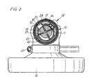
- the motor 11 comprises a cylinder or stator 22 which is formed with a cylindrical chamber 23, two axially directed pressure air inlet ports 24 and a laterally directed exhaust air outlet port 25.
- a rotor 26 carrying radially movable vanes 27.
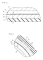
- the housing 10 comprises a cylindrical wall 28 with a cylindrical inner surface 29. See Figs. 1, 2 and 4. Between the surface 29 and the motor stator 22 there is formed a substantially tubular space 30. Within the tubular space 30 there is disposed a heat screen in the form of a tubular sheet metal shell 32. Although other types material, as for instance plastics, might be used, sheet metal is superior since it makes it possible to keep down the thickness of the shell 32 to a few tenths of a millimeter, and thereby to keep down the outer transverse dimension of the tool housing for a certain motor size.
- the heat screening effect of the shell 32 is based on the low heat transition coefficient existing between a gaseous medium and a solid material, and by the introduction of a heat screening shell 32 between the motor stator 22 and the housing 10 there is formed two extra air-to-metal heat transitions which effectively retard the heat transfer between the motor and the housing.
- first air gap 33 between the shell 32 and the inner surface 29 of the housing 10, there is formed a first air gap 33, and between the shell 32 and the stator 22 there is formed a second air gap 34.
- the second air gap 34 though, is several times wider than the first air gap 33 and is adapted to form a part of the exhaust air passage for communicating exhaust air from the motor outlet port 25 to the rear end of the housing 10 and the exhaust outlet 15.
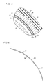
- the first air gap 33 between the shell 32 and the inner surface 29 of the housing 10 is very narrow, and it is to be noted that the air gap necessary to obtain the low heat transition coefficient could be very small, down to molecule size. This means that there is in fact no need for any means to keep up the size of the air gap. In some cases, though, it might be useful to provide the shell 32 with some kind of distance keeping means.
- Fig. 6 shows a fraction of a heat screening shell 52 which is formed with punched-out dents forming projections 53 on the outside of the shell 52. By spreading a number of such projections 53 over the shell 52 a certain width of the air gap 33 relative to the surface 29 is positively maintained.
- the heat screening concept of the invention is based on the low gas-to-solid material heat transition coefficient, and not at all on the heat insulating properties of the very material used for the heat screening shells. This means that the heat screening shells in themselves have substantially no heat insulating properties. Should, accordingly, the heat screening shells be made of a plastic material, which material has fairly good heat insulating properties, the shells are thin enough not to offer any heat insulation by themselves. So, regardless of what material is used for the heat screening shells, the shells have in themselves substantially no heat insulating properties.
- FIG. 5 there is illustrated an embodiment of the invention including two tubular shells 32a, 32b arranged coaxially with each other with one of them disposed inside the other leaving an air gap 36 between them.
- This arrangement means that the heat transfer between the motor and the housing is further retarded, because the employment of two heat screening shells means four serial gas-to-metal heat transitions, each with a low heat transition coefficient.
- pressure air is supplied through the air inlet 12 and fed to the motor 11 via the throttle valve 13 and the air inlet ports 24.
- the pressure air starts acting on the rotor vanes 27, thereby rotating the rotor 26.
- the air is exhausted through the outlet port 25 into the tubular space 30 between the stator 22 and the inner surface 29 of the housing 10, specifically, the second air gap 34 between the stator 22 and the heat screening shell 32.
- the invention is equally applicable on an electric power tool where the heat screen is intended to operate the other way round, namely to reduce heat transfer from the motor to the housing.
- the heat developed in the electric motor has to pass at least four transition steps between gaseous media and metal surfaces before reaching the operators hands.
Landscapes
- Engineering & Computer Science (AREA)
- Mechanical Engineering (AREA)
- Motor Or Generator Cooling System (AREA)
- Portable Power Tools In General (AREA)
- Secondary Cells (AREA)
- Manipulator (AREA)
- Cooling Or The Like Of Electrical Apparatus (AREA)
Applications Claiming Priority (2)
| Application Number | Priority Date | Filing Date | Title |
|---|---|---|---|
| SE9802778A SE520071C2 (sv) | 1998-08-20 | 1998-08-20 | Portabelt kraftverktyg med värmeavskärmande organ |
| SE9802778 | 1998-08-20 |
Publications (2)
| Publication Number | Publication Date |
|---|---|
| EP0980743A1 true EP0980743A1 (de) | 2000-02-23 |
| EP0980743B1 EP0980743B1 (de) | 2003-11-05 |
Family
ID=20412293
Family Applications (1)
| Application Number | Title | Priority Date | Filing Date |
|---|---|---|---|
| EP99850125A Expired - Lifetime EP0980743B1 (de) | 1998-08-20 | 1999-08-19 | Tragbares kraftbetriebenes Werkzeug mit wärmeabsorbierendem Schild |
Country Status (5)
| Country | Link |
|---|---|
| US (1) | US6163094A (de) |
| EP (1) | EP0980743B1 (de) |
| JP (1) | JP2000061869A (de) |
| DE (1) | DE69912548T2 (de) |
| SE (1) | SE520071C2 (de) |
Cited By (5)
| Publication number | Priority date | Publication date | Assignee | Title |
|---|---|---|---|---|
| EP1627709A3 (de) * | 2004-08-20 | 2007-11-21 | Ingersoll-Rand Company | Strömungsführung für druckmittelbetätigten Werkzeugen und damit ausgerüstete Werkzeugs |
| WO2008113893A3 (en) * | 2007-03-21 | 2009-02-05 | Kwh Mirka Ab Oy | Compact electric grinding machine |
| EP1682297A4 (de) * | 2003-10-28 | 2009-11-11 | Ibex Ind Ltd | Kraftbetriebenes handwerkzeug |
| CN101636245B (zh) * | 2007-03-21 | 2012-07-04 | Kwh米亚卡公司 | 紧凑式电打磨机 |
| CN103978466A (zh) * | 2014-05-22 | 2014-08-13 | 王静 | 一种气压式磨光机转轴装置 |
Families Citing this family (6)
| Publication number | Priority date | Publication date | Assignee | Title |
|---|---|---|---|---|
| USD472440S1 (en) | 2001-12-13 | 2003-04-01 | Devilbiss Air Power Company | Pneumatic tool |
| US8040005B2 (en) * | 2008-02-08 | 2011-10-18 | Robert Bosch Gmbh | Plastic pole housing for an electric motor |
| ITMI20080407U1 (it) * | 2008-12-11 | 2010-06-12 | Valentini Guido | Impugnatura per macchine pneumatiche per la lavorazione di superfici |
| USD661563S1 (en) | 2011-06-07 | 2012-06-12 | Metabowerke Gmbh | Polishing machine |
| US11139722B2 (en) | 2018-03-02 | 2021-10-05 | Black & Decker Inc. | Motor having an external heat sink for a power tool |
| DE102019220251A1 (de) * | 2019-12-19 | 2021-06-24 | Robert Bosch Gmbh | Fingerschutz für Drehschlagschrauber |
Citations (3)
| Publication number | Priority date | Publication date | Assignee | Title |
|---|---|---|---|---|
| US2789652A (en) * | 1953-11-05 | 1957-04-23 | Fannen John | Muffling device for pneumatic tools of the turbine type |
| GB1437304A (en) * | 1973-07-14 | 1976-05-26 | Metabowerke Kg | Motordriven portable tool with sound-absorbing housing |
| DE4238564A1 (de) * | 1992-11-14 | 1994-05-19 | Fein C & E | Elektrowerkzeug mit Absaugung |
Family Cites Families (4)
| Publication number | Priority date | Publication date | Assignee | Title |
|---|---|---|---|---|
| SE446698B (sv) * | 1983-09-16 | 1986-10-06 | Atlas Copco Ab | "handhallet maskinverktyg innefattande ett motorhus och tva pa huset monterade handtag av vilka atminstone det ena er instellbart anordnat" |
| SE442963B (sv) * | 1984-05-07 | 1986-02-10 | Atlas Copco Ab | Vibrationsisolerande handtag |
| US5136197A (en) * | 1991-06-25 | 1992-08-04 | Clarence Hallett | Reaction containment drive for power tool |
| US5669453A (en) * | 1994-10-07 | 1997-09-23 | Ryobi Limited | Power carving tool |
-
1998
- 1998-08-20 SE SE9802778A patent/SE520071C2/sv not_active IP Right Cessation
-
1999
- 1999-08-19 DE DE69912548T patent/DE69912548T2/de not_active Expired - Fee Related
- 1999-08-19 US US09/376,022 patent/US6163094A/en not_active Expired - Lifetime
- 1999-08-19 EP EP99850125A patent/EP0980743B1/de not_active Expired - Lifetime
- 1999-08-20 JP JP11234602A patent/JP2000061869A/ja active Pending
Patent Citations (3)
| Publication number | Priority date | Publication date | Assignee | Title |
|---|---|---|---|---|
| US2789652A (en) * | 1953-11-05 | 1957-04-23 | Fannen John | Muffling device for pneumatic tools of the turbine type |
| GB1437304A (en) * | 1973-07-14 | 1976-05-26 | Metabowerke Kg | Motordriven portable tool with sound-absorbing housing |
| DE4238564A1 (de) * | 1992-11-14 | 1994-05-19 | Fein C & E | Elektrowerkzeug mit Absaugung |
Cited By (6)
| Publication number | Priority date | Publication date | Assignee | Title |
|---|---|---|---|---|
| EP1682297A4 (de) * | 2003-10-28 | 2009-11-11 | Ibex Ind Ltd | Kraftbetriebenes handwerkzeug |
| EP1627709A3 (de) * | 2004-08-20 | 2007-11-21 | Ingersoll-Rand Company | Strömungsführung für druckmittelbetätigten Werkzeugen und damit ausgerüstete Werkzeugs |
| US7770661B2 (en) | 2004-08-20 | 2010-08-10 | Ingersoll-Rand Company | Intermediate and assembly assistance components for fluid driven tools and tools incorporating the same |
| WO2008113893A3 (en) * | 2007-03-21 | 2009-02-05 | Kwh Mirka Ab Oy | Compact electric grinding machine |
| CN101636245B (zh) * | 2007-03-21 | 2012-07-04 | Kwh米亚卡公司 | 紧凑式电打磨机 |
| CN103978466A (zh) * | 2014-05-22 | 2014-08-13 | 王静 | 一种气压式磨光机转轴装置 |
Also Published As
| Publication number | Publication date |
|---|---|
| JP2000061869A (ja) | 2000-02-29 |
| EP0980743B1 (de) | 2003-11-05 |
| SE9802778L (sv) | 2000-02-21 |
| DE69912548T2 (de) | 2004-09-23 |
| SE9802778D0 (sv) | 1998-08-20 |
| SE520071C2 (sv) | 2003-05-20 |
| US6163094A (en) | 2000-12-19 |
| DE69912548D1 (de) | 2003-12-11 |
Similar Documents
| Publication | Publication Date | Title |
|---|---|---|
| US6163094A (en) | Portable power tool with a heat screening means | |
| US12127378B2 (en) | Heatsink clamp for multiple electronic components | |
| US6971456B2 (en) | Electric power tool | |
| US7660110B2 (en) | Computer system with motor cooler | |
| JP4654041B2 (ja) | 電動機用冷却装置 | |
| EP3760375A1 (de) | Exzentrischer mechanismus und elektrowerkzeug | |
| IT9067849A1 (it) | Motoventilatore, particolarmente per autoveicoli | |
| AU2015227403A1 (en) | Air-cooled electric machine and method of assembling the same | |
| US2989995A (en) | Composite air-directing and heatdissipating gear housings | |
| US11063495B2 (en) | Heatsink clamp for multiple electronic components | |
| US5751079A (en) | Alternator with internal and external fans | |
| US5445218A (en) | Compact heat exchanger | |
| GB2382543A (en) | Hand machine tool with air openings in housing and movable cover | |
| US4073338A (en) | Heat exchangers | |
| US20240322640A1 (en) | Motor radiator | |
| US10886866B1 (en) | Motor controller with inductor mounted transverse to control board | |
| KR101636259B1 (ko) | 모터하우징 | |
| US20090280731A1 (en) | Electric Portable Grinder With Air Cooling System | |
| KR101772330B1 (ko) | 냉각 장치가 구비된 공작 기계의 주축 장치 및 그 주축 장치를 갖는 공작 기계 | |
| CN108312018B (zh) | 一种手持式电动工具 | |
| CN218817237U (zh) | 一种轴流风机的散热结构 | |
| CN217883070U (zh) | 一种圆砂机的电机结构 | |
| JPS5656147A (en) | Ac motor for car | |
| CN216421087U (zh) | 一种电主轴结构及加工车床 | |
| CN220273423U (zh) | 一种电动工具的电机结构 |
Legal Events
| Date | Code | Title | Description |
|---|---|---|---|
| PUAI | Public reference made under article 153(3) epc to a published international application that has entered the european phase |
Free format text: ORIGINAL CODE: 0009012 |
|
| AK | Designated contracting states |
Kind code of ref document: A1 Designated state(s): DE FR GB IT |
|
| AX | Request for extension of the european patent |
Free format text: AL;LT;LV;MK;RO;SI |
|
| 17P | Request for examination filed |
Effective date: 20000717 |
|
| AKX | Designation fees paid |
Free format text: DE FR GB IT |
|
| 17Q | First examination report despatched |
Effective date: 20020628 |
|
| GRAH | Despatch of communication of intention to grant a patent |
Free format text: ORIGINAL CODE: EPIDOS IGRA |
|
| GRAS | Grant fee paid |
Free format text: ORIGINAL CODE: EPIDOSNIGR3 |
|
| GRAA | (expected) grant |
Free format text: ORIGINAL CODE: 0009210 |
|
| AK | Designated contracting states |
Kind code of ref document: B1 Designated state(s): DE FR GB IT |
|
| REG | Reference to a national code |
Ref country code: GB Ref legal event code: FG4D |
|
| REF | Corresponds to: |
Ref document number: 69912548 Country of ref document: DE Date of ref document: 20031211 Kind code of ref document: P |
|
| ET | Fr: translation filed | ||
| PLBE | No opposition filed within time limit |
Free format text: ORIGINAL CODE: 0009261 |
|
| STAA | Information on the status of an ep patent application or granted ep patent |
Free format text: STATUS: NO OPPOSITION FILED WITHIN TIME LIMIT |
|
| 26N | No opposition filed |
Effective date: 20040806 |
|
| PGFP | Annual fee paid to national office [announced via postgrant information from national office to epo] |
Ref country code: DE Payment date: 20080905 Year of fee payment: 10 |
|
| PGFP | Annual fee paid to national office [announced via postgrant information from national office to epo] |
Ref country code: IT Payment date: 20080827 Year of fee payment: 10 Ref country code: FR Payment date: 20080818 Year of fee payment: 10 |
|
| PGFP | Annual fee paid to national office [announced via postgrant information from national office to epo] |
Ref country code: GB Payment date: 20080827 Year of fee payment: 10 |
|
| GBPC | Gb: european patent ceased through non-payment of renewal fee |
Effective date: 20090819 |
|
| REG | Reference to a national code |
Ref country code: FR Ref legal event code: ST Effective date: 20100430 |
|
| PG25 | Lapsed in a contracting state [announced via postgrant information from national office to epo] |
Ref country code: FR Free format text: LAPSE BECAUSE OF NON-PAYMENT OF DUE FEES Effective date: 20090831 Ref country code: DE Free format text: LAPSE BECAUSE OF NON-PAYMENT OF DUE FEES Effective date: 20100302 |
|
| PG25 | Lapsed in a contracting state [announced via postgrant information from national office to epo] |
Ref country code: GB Free format text: LAPSE BECAUSE OF NON-PAYMENT OF DUE FEES Effective date: 20090819 |
|
| PG25 | Lapsed in a contracting state [announced via postgrant information from national office to epo] |
Ref country code: IT Free format text: LAPSE BECAUSE OF NON-PAYMENT OF DUE FEES Effective date: 20090819 |