EP0980745A2 - Dispositif de coupe de pierre ayant des moyens anti-glissement pour une courroie de coupe diamantée - Google Patents
Dispositif de coupe de pierre ayant des moyens anti-glissement pour une courroie de coupe diamantée Download PDFInfo
- Publication number
- EP0980745A2 EP0980745A2 EP99115672A EP99115672A EP0980745A2 EP 0980745 A2 EP0980745 A2 EP 0980745A2 EP 99115672 A EP99115672 A EP 99115672A EP 99115672 A EP99115672 A EP 99115672A EP 0980745 A2 EP0980745 A2 EP 0980745A2
- Authority
- EP
- European Patent Office
- Prior art keywords
- belt
- arm
- machine
- diamond
- guiding arm
- Prior art date
- Legal status (The legal status is an assumption and is not a legal conclusion. Google has not performed a legal analysis and makes no representation as to the accuracy of the status listed.)
- Granted
Links
- 229910003460 diamond Inorganic materials 0.000 title claims abstract description 83
- 239000010432 diamond Substances 0.000 title claims abstract description 83
- 238000005520 cutting process Methods 0.000 title claims abstract description 67
- 239000004575 stone Substances 0.000 title claims abstract description 35
- 239000012530 fluid Substances 0.000 claims description 11
- 239000010438 granite Substances 0.000 claims description 4
- -1 marbles Substances 0.000 claims description 2
- 238000004140 cleaning Methods 0.000 claims 1
- 230000001050 lubricating effect Effects 0.000 claims 1
- 238000010276 construction Methods 0.000 description 6
- 230000002093 peripheral effect Effects 0.000 description 5
- 230000000295 complement effect Effects 0.000 description 4
- 239000003638 chemical reducing agent Substances 0.000 description 3
- 230000002787 reinforcement Effects 0.000 description 3
- 230000000694 effects Effects 0.000 description 2
- XLYOFNOQVPJJNP-UHFFFAOYSA-N water Substances O XLYOFNOQVPJJNP-UHFFFAOYSA-N 0.000 description 2
- 238000000605 extraction Methods 0.000 description 1
- 238000003780 insertion Methods 0.000 description 1
- 230000037431 insertion Effects 0.000 description 1
- 230000010354 integration Effects 0.000 description 1
- 239000000314 lubricant Substances 0.000 description 1
- 239000004579 marble Substances 0.000 description 1
- 239000000463 material Substances 0.000 description 1
- 238000000034 method Methods 0.000 description 1
- 230000035515 penetration Effects 0.000 description 1
Images




Classifications
-
- B—PERFORMING OPERATIONS; TRANSPORTING
- B28—WORKING CEMENT, CLAY, OR STONE
- B28D—WORKING STONE OR STONE-LIKE MATERIALS
- B28D1/00—Working stone or stone-like materials, e.g. brick, concrete or glass, not provided for elsewhere; Machines, devices, tools therefor
- B28D1/02—Working stone or stone-like materials, e.g. brick, concrete or glass, not provided for elsewhere; Machines, devices, tools therefor by sawing
- B28D1/08—Working stone or stone-like materials, e.g. brick, concrete or glass, not provided for elsewhere; Machines, devices, tools therefor by sawing with saw-blades of endless cutter-type, e.g. chain saws, i.e. saw chains, strap saws
Definitions
- This invention relates to a machine for cutting stones, such as marbles, granites and others, and particularly for cutting slabs from a stone block, for dividing a stone block into slabs having a predetermined thickness, for squaring stone blocks, and for other similar tasks, in which machine cutting operations are performed by at least one endless diamond belt, or the like, which slidably extends in the cutting plane around a belt-guiding arm substantially parallel to the cutting line and is returned on pulleys disposed at the ends of this arm, one of which is a driving pulley, and which diamond belt is guided with its active branch transverse to the cutting plane by grooved guide means provided on the longitudinal edge of the belt-guiding arm turned towards the cutting line and with its inactive return branch in grooved guide means provided on the edge of the belt-guiding arm opposite to the cutting line, the belt-guiding arm being translatable parallel to itself and to the cutting line in the cutting plane, and means being provided for moving the belt-guiding arm so that it can be first engaged with the stone block by the active branch of the diamond belt along
- the inner side of the diamond belt i.e. the side turned towards the belt-guiding arm and not provided with diamond surfaces
- the grooves of the guide means have complementary and coincident cross sectional profiles, preferably tapering towards the bottom of the grooves, and particularly V-profiles, at least partly slidably engaged with each other.
- the slab cut from the stone block may happen to tilt towards the block during the cutting operation or following it, exerting transverse forces on the inactive return branch of the diamond belt, such as to cause this branch to slip, i.e. come off the associated groove/s of the guide means while the cutting operation is still in progress or at the end of it, upon extraction of the belt-guiding arm through the cutting slot between the block and the slab cut therefrom, by a corresponding translatory movement opposite to cut advancement.
- the invention aims at obviating the above drawback and provides, therefore, along the edge of the belt-guiding arm opposite to the cutting line, so-called anti-slippage means, which are arranged at least partially over the inactive return branch of the diamond belt and prevent it from disengaging from the associated groove/s of the guide means provided on the corresponding longitudinal edge of the belt-guiding arm.
- such anti-slippage means may be also provided for the active branch of the diamond belt, at the segments between the stone block and the diamond belt return pulleys, which are disposed at the two ends of the belt-guiding arm.
- the anti-slippage means in accordance with the invention may have any type of construction suitable for this purpose.
- these anti-slippage means may also consist of simple stationary protection means, overlaying laterally and/or above the diamond belt, covering it at least partially, preferably without coming to contact with it, and preventing any action thereon by forces which could cause it to come off the guide groove/s provided on the longitudinal edge of the belt guiding an.
- These protecting and covering means may be continuous or discontinuous, i.e. may extend continuously as a shield along most of the inactive return branch of the diamond belt and/or along the side segments of the active branch of the diamond belt, or may be arranged at intervals along said branch and/or along said segments of the belt.
- the anti-slippage means consist of loose guide wheels which are arranged at least partially over the outer surface of the diamond belt and may be also very close thereto and possibly in contact or nearly in contact therewith.
- the anti-slippage means according to the invention may be mounted at least partly on the belt-guiding arm and/or at least partly on an an carrier, whereon the belt-guiding arm and the diamond belt return pulleys at the ends of said arm are also mounted, as well as the means for driving said belt and/or the belt-guiding arm, and which arm carrier is guided in a frame in such a way that it can be translated parallel to the cutting plane and transverse to the cutting line.
- the belt-guiding arm is delimited, on the side turned towards the cutting line and on the opposite side, by two corresponding separate substantially parallel longitudinal members, substantially parallel to each other and to the cutting line and connected to each other and/or to the bearing structure of the belt-guiding arm, as well as provided, at their longitudinal edges, with grooved guide means or with mounts for said diamond belt guide means.
- one type of prefabricated longitudinal member may be used to make the two opposite longitudinal parts of the belt-guiding arm, said type of member having grooved guide means or mounts therefor, on a convex longitudinal edge, and an opposite longitudinal edge which is rectilinear or anyway profiled as appropriate for its integration into the belt-guiding arm or into its bearing structure, and said type of member being mounted on each longitudinal edge of the belt-guiding arm, with its convex side, provided with the grooved guide means or with the mounts therefor, being always turned outwards.
- a peripheral groove may be provided, which is continuous or in sections, in the outer longitudinal edges of the arm or in the edges of the longitudinal members which are to form the upper and lower outer sides of the arm.
- sliding motion is enhanced by supplying a lubricant fluid into the guide groove, particularly forming a slide bearing, for example with an effect known as "aquaplaning".
- the guide means consist of wheels, pulleys or rollers which are rotatably mounted on the outer peripheral edges of the arm or on the edges of the longitudinal members which are to form the outer peripheral edges of the arm.
- the rollers have annular coaxial grooves whose section is complementary or substantially coincident with the longitudinal guide rib of the belt.
- the rollers are aligned and installed along the longitudinal edges of the arm or the outer edges of the longitudinal members so that the rollers and the means for supporting them are narrower than the belt.
- means for supplying a fluid onto the rollers may be provided, although this fluid is mainly used to wash cutting residues away from the rotational supports of the rollers.
- the grooved guide means may also consist of combinations of rollers and grooves with or without sliding fluid feed, alternated in any order, either within one of the two outer longitudinal edges of the arm, or between the two opposite longitudinal edges.
- the edge associated to the return branch may bear the guide rollers
- the edge associated to the cutting branch of the belt may be provided with the grooved wherein the sliding fluid is supplied.
- the machine which, thanks to the above characteristics has a comparatively slim and substantially lighter and smaller construction may be mounted in such a manner as to be able to slide on guides, such as rails or the like along a predetermined path and transverse, particularly perpendicular to the cutting plane.
- the block to be processed may be stationary, whereas it can be divided into slabs by moving the machine. Also, the machine may follow a path developing along a plurality of aligned blocks to be processed, thereby avoiding the need to load each block on cars.
- the machine according to the invention is mainly used to cut up blocks B of stone (marbles, granites, and others) into slabs with a predetermined thickness, and is composed of a base 1, whereon a portal frame 2 is fitted.
- a vertical arm carrier 5 is slidably guided on vertical guides 3 of the uprights of the portal frame 2, by means of corresponding brackets 4.
- return pulleys 6, disposed in a common vertical plane and about which an endless flexible diamond belt 7 is driven, are rotatably mounted.
- the arm carrier 5 may be displaced vertically by means of pinions 8, mounted on the carrier 5, and driven by motor reducers 9, while meshing with vertical racks 10 disposed on the uprights of the mount 2.
- One of the return pulleys 6 is rotatably driven by a motor reducer 15 installed on the arm carrier 5.
- the arm carrier 5 preferably has an inverted U-shape and in the lower part between the U stems a belt-guiding arm 14 is fastened, which is substantially horizontal and extends in a vertical cutting plane.
- This belt-guiding arm 14 is as thin as possible transversely to the cutting plane, in so far as mechanical and functional needs of the arm 14 and of the diamond belt 7 allow.
- the upper and lower longitudinal edges of the belt-guiding arm 14 may be rectilinear, but - in the illustrated embodiment - are curved, i.e. slightly outwardly convex, each having a longitudinal groove, wherein the corresponding upper or lower branches of the diamond belt 7 are slidably driven.
- the diamond belt 7 has one or more longitudinal cables or wires 20, embedded in a body 21 made of a flexible material, particularly or rubber or plastic.
- this body 21 of the diamond belt 7 has, on its outer side, i.e. opposite to the belt-guiding arm 14, a substantially plane surface, wherefrom diamond segments 22, spaced in the longitudinal direction of the belt 7 and fastened to the longitudinal cables or wires 20 thereof, as well as at least partially embedded in the body 21, project slightly.
- each diamond segment 22 extends transversely to the belt 7 all over the width of said outer surface.
- each diamond segment 22 also extends over a part of the two sides of the belt 7, slightly projecting, also on these sides, out of the flexible body 21 of the belt 7.
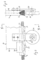
- each diamond segment 22 has an extension on one side of the belt 7, towards the thickness of the belt 7 and towards the inner side thereof, which is longer than that on the opposite side. This asymmetric profile is alternately and specularly inverted in the following diamond segments 22, as is evident in figs. 3 and 5.
- the body 21 of the belt 7 On the inner side, turned towards the belt-guiding arm 14 and opposite to the stone block B to be cut and to the diamond segments 22, the body 21 of the belt 7 has a V-shaped part which is complementary to the cross section of the longitudinal grooves 17 of the upper and lower edges of the belt-guiding arm 14 and is slidably engaged in these grooves 17.
- the maximum width of the body 21 of the diamond belt 7 (out of the grooves 17 of the belt-guiding arm 14) substantially corresponds to the width of the lower part of the belt-guiding arm 14, whereas the diamond sectors 22 are slightly wider. So, the diamond sectors 22 project on both sides slightly beyond the width of the body 21 of the belt 7 and of the belt-guiding arm 14.
- the belt slides in the guide grooves 17 with the help of fluid supplied with a method known per se, by means of feed nozzles connected to a feed circuit typically provided inside the arm 14.
- the sliding fluid particularly water, forms a slide bearing, which reduces sliding friction with an effect similar to the so-called aquaplaning.
- the belt-guiding arm 14 is upwardly and downwardly delimited by two separate longitudinal members 16, which may be vertically spaced and are fastened by their ends to the uprights of the arm carrier 5 and possibly even to each other in one or more intermediate locations.
- These two longitudinal members 16 are made from the same type of prefabricated longitudinal member, which has a rectilinear or slightly convex longitudinal edge, provided with the guide groove 17 for the diamond belt 7 and an opposite longitudinal edge, with no guide groove for the diamond belt thereon, which may have any type of profile, e.g. rectilinear, as shown.
- This single type of longitudinal member 16 is mounted both at the upper longitudinal edge and at the lower longitudinal edge of the belt-guiding arm 14, with its grooved edge, either rectilinear or convex, turned outwards, as particularly apparent in fig. 1.
- numeral 30 denotes reinforcement blocks, which may be fastened at the lower corners of the belt-guiding arm 14, out of the part thereof which is intended for penetration into the stone block B.
- These reinforcement blocks 30 have, coaxially to the groove 17 of the lower longitudinal edge of the belt-guiding arm 14, lead-in grooves which have the same profiles as the groove 17, but are wider than it and act as an aid for insertion of the diamond belt 7. Obviously, these reinforcement and lead-in grooved blocks may also not be present.
- the block B of stone (marble, granite, or the like) is positioned, to be cut up, for instance, by the above described machine, into individual slabs having a predetermined thickness.
- the stone block B is placed on a car 28, which can run on rails 29 horizontally and transversely to the belt-guiding arm 14 and to the associated active lower branch of the diamond belt 7.
- the diamond belt 7 In order to cut the stone block B, the diamond belt 7 is slid in the direction of its length by its driving return pulley, whereas the arm carrier 5 is lowered to bring the lower active branch of the diamond belt 7 to contact with the stone block B.
- the arm carrier 5 is further lowered by a continuous vertical translatory motion thanks to the motor reducers 9, to the pinions 8 and to the racks and at a uniform speed, corresponding to the speed whereat the stone block B is cut by the lower active branch of the diamond belt 7.
- the lower active branch of the diamond belt 7 is accurately and safely guided by providing that the inner profiled part of the body 21 of the diamond belt 7 is engaged in the accordingly profiled groove 17 of the belt-guiding arm 14.
- the belt-guiding arm 14 keeps the associated underlying lower active branch of the diamond belt 7 in contact with the stone block B and presses it with the necessary force against said block, i.e. against the bottom of the cutting slot made in the block B and that the belt-guiding arm 14 penetrates.
- the arm carrier 5 is lifted together with the belt-guiding arm 14 and with the diamond belt 7, and then the stone block B is moved, by the car 28 on the rails 29, one step further, corresponding to the thickness of one slab, whereupon the following cutting operation is performed as described above.
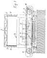
- anti-slippage wheels 23 are provided above the belt-guiding arm 14, which are mounted in such a way as to rotate loosely, by support brackets 25, on a part 24 of the arm carrier 5 and are arranged at intervals along the upper grooved longitudinal edge of the belt-guiding arm 14, i.e.
- These anti-slippage wheels 23 are arranged at least partly over the upper inactive return branch of the diamond belt 7 and may be at a small distance from said belt 7 or may be in contact therewith.
- these anti-slippage wheels 23 prevent the upper inactive return branch of the diamond belt 7 from being lifted to such an extent as to disengage from its respective longitudinal guide groove 17 formed in the corresponding upper edge of the belt-guiding arm 14, i.e. in its respective longitudinal member 16.
- an anti-slippage wheel 26 is provided, which is mounted by a support bracket 27 on the overlying belt-guiding arm 14, i.e. on its respective longitudinal member 16, and is superposed from below to said lower active branch of the diamond belt 7, thereby preventing it to slip, i.e. to come off the longitudinal guide groove 17 of the lower edge of the belt-guiding arm 14, i.e. of its respective longitudinal member 16, as shown, particularly, in figs. 1, 3 and 4.
- Fig. 7 shows a variant embodiment of the machine as described hereinbefore with reference to figs. 1 to 6.
- the differences consist first in that, in lieu of the longitudinal groove 17, the arm 14 has a plurality of peripheral wheels, rollers or pulleys 17', arranged at predetermined intervals along the sliding edges of the inactive and active branches of the diamond belt 7 in any order.
- Each pulley 17' has an annular coaxial throat 117' and is rotatably fitted in an accommodating throat 114 of the peripheral edge of the arm 14.
- the overall thickness of the arm 14 with the wheels 17' and the rotational supports is smaller than that of the diamond teeth of the belt.
- the construction of the arm 14 may be identical to that of the previous embodiment, providing the same advantages as mentioned above. Furthermore, as regards the arched profile of the two opposite outer edges of the arm 114, associated to the inactive and active branches of the belt 7 respectively, this embodiment allows to obtain this profile by simply changing the diameter of the grooved wheels or rollers 17' depending on their position. By increasing the diameter of the pulleys or rollers 17' symmetrically to the transverse median axis of the arm 14, an arched profile of the corresponding branch of the diamond belt 7 can be obtained from a substantially rectangular shape of the arm, or of the longitudinal members 16 composing it.
- one of the two outer edges of the arm 14 may be made according to the embodiment of figs. 1 to 6, i.e. provided with the groove on its longitudinal edge, whereas the other may have the grooved rollers, wheels or pulleys 17'.
- one or both opposite longitudinal edges of the arm 14 may have combinations of segments of grooves 17 and grooved rollers, wheels or pulleys 17'.
- a fluid feed e.g. of water or the like may be provided, though only having, in this case, the function of keeping the rotational supports of said rollers 17' or similar clean.
- Fig. 7 also shows a further difference with respect to the embodiment of figs. 1 to 6.
- the machine is supported on a car 30, which slides or guides, e.g. rails 31, like the block-carrying car of the previous example.
- the block B to be cut is stationary.
- the moving direction is transverse to the cutting plane and the latter is moved relative to the block by moving the machine.
- the path run by the machine may develop along a plurality of successive aligned blocks to be cut. This is particularly advantageous, because it doesn't require cranes for moving blocks from the storing site onto the cutting car. Blocks may be simply unloaded onto the storing site in the predetermined order for cutting, i.e. in any location of the path run by the machine and may be processed whenever need thereof arises.
- the invention is not limited to the above described and illustrated embodiment, but may be greatly varied and modified especially as regards construction and within the range of mechanical equivalents.
- the arrangement of the anti-slippage means and the composition of the belt-guiding arm from two longitudinal members consisting of the same type of prefabricated longitudinal member may be used, either in combination or separately, in any machine as described herein, regardless of the particular construction thereof and of its respective diamond belt.
- even two or more adjacent and parallel belt-guiding arms 14 may be mounted on the arm carrier 5, each associated to a diamond belt 7, so that two or more parallel cuts may be simultaneously made in the stone block B.
- the arm carrier 5 may be translated parallel to itself not only in a vertical plane, as described in the illustrated embodiment, but in a plane having any orientation in space and/or not only vertically from top to bottom, but, for instance, even horizontally, from one side to the opposite one, while orienting the belt-guiding arm 14 accordingly. All this without departure from the guiding principle disclosed above and claimed below.
Landscapes
- Engineering & Computer Science (AREA)
- Mining & Mineral Resources (AREA)
- Mechanical Engineering (AREA)
- Processing Of Stones Or Stones Resemblance Materials (AREA)
- Polishing Bodies And Polishing Tools (AREA)
- Grinding-Machine Dressing And Accessory Apparatuses (AREA)
Applications Claiming Priority (2)
| Application Number | Priority Date | Filing Date | Title |
|---|---|---|---|
| ITSV980048 | 1998-08-20 | ||
| IT1998SV000048A IT1305970B1 (it) | 1998-08-20 | 1998-08-20 | Macchina ad almeno una cinghia diamantata per il taglio di pietre. |
Publications (3)
| Publication Number | Publication Date |
|---|---|
| EP0980745A2 true EP0980745A2 (fr) | 2000-02-23 |
| EP0980745A3 EP0980745A3 (fr) | 2002-03-13 |
| EP0980745B1 EP0980745B1 (fr) | 2003-12-17 |
Family
ID=11408299
Family Applications (1)
| Application Number | Title | Priority Date | Filing Date |
|---|---|---|---|
| EP99115672A Expired - Lifetime EP0980745B1 (fr) | 1998-08-20 | 1999-08-09 | Dispositif de coupe de pierre ayant des moyens anti-glissement pour une courroie de coupe diamantée |
Country Status (4)
| Country | Link |
|---|---|
| EP (1) | EP0980745B1 (fr) |
| AT (1) | ATE256543T1 (fr) |
| DE (1) | DE69913616D1 (fr) |
| IT (1) | IT1305970B1 (fr) |
Cited By (7)
| Publication number | Priority date | Publication date | Assignee | Title |
|---|---|---|---|---|
| DE10042858A1 (de) * | 2000-08-30 | 2002-03-21 | Dieter Gerlach | Anordnung zum Sägen von Platten aus steinartigen Baustoffen |
| EP1316398A3 (fr) * | 2001-11-30 | 2004-07-28 | Benetti Impianti S.r.l. | Dispositif pour la découpe de fines dalles d'un bloc grossier plus épais, et procédé de fabrication des panneaux recouverts desdites fines dalles |
| ITVR20080099A1 (it) * | 2008-09-05 | 2010-03-06 | Marmi Zenatelli S R L | Dispositivo di taglio particolarmente per macchine per il taglio di materiali lapidei |
| ITVR20080100A1 (it) * | 2008-09-05 | 2010-03-06 | Marmi Zenatelli S R L | Macchina per il taglio particolarmente di materiali lapidei |
| CN102198705A (zh) * | 2011-05-10 | 2011-09-28 | 山东大学 | 多绳金刚石串珠锯进给托板导向机构 |
| ITLU20120017A1 (it) * | 2012-12-06 | 2014-06-07 | Giorgio Dinelli | Utensile diamantato da utilizzare in macchine per il taglio di materiali lapidei |
| CN116141503A (zh) * | 2023-01-10 | 2023-05-23 | 清远南玻节能新材料有限公司 | 玻璃切割机 |
Families Citing this family (1)
| Publication number | Priority date | Publication date | Assignee | Title |
|---|---|---|---|---|
| CN111843043A (zh) * | 2020-08-21 | 2020-10-30 | 壶关高测新材料科技有限公司 | 一种环形金刚石线锯切割机 |
Family Cites Families (7)
| Publication number | Priority date | Publication date | Assignee | Title |
|---|---|---|---|---|
| US2362979A (en) * | 1944-01-08 | 1944-11-21 | Contour Saws | Abrasive band |
| DE2154428A1 (de) * | 1971-11-02 | 1973-05-03 | Tullius Theresia | Drahtsaege mit gefuehrten diamantschneidkoerpern zum zerteilen von gesteinsbloecke |
| JPS6478802A (en) * | 1987-09-19 | 1989-03-24 | Daiwa Kikai Seisakusho | Cutting of high-hardness brittle material cutting machine utilizing diamond wire saw |
| US5181503A (en) * | 1991-06-26 | 1993-01-26 | W. F. Meyers Company, Inc. | Stone slab saw |
| WO1996004093A1 (fr) * | 1994-07-29 | 1996-02-15 | 'diamant Boart' | Procede et dispositif de commande d'un cable ou fil, en particulier diamante, pour la coupe dans des blocs |
| IT1282487B1 (it) * | 1995-11-08 | 1998-03-23 | Benetti Meyers International S | Cinghietta diamantata per il taglio di pietre. |
| DE19754520A1 (de) * | 1997-12-09 | 1999-06-10 | Wolfgang Mayer | Seilsäge |
-
1998
- 1998-08-20 IT IT1998SV000048A patent/IT1305970B1/it active
-
1999
- 1999-08-09 EP EP99115672A patent/EP0980745B1/fr not_active Expired - Lifetime
- 1999-08-09 AT AT99115672T patent/ATE256543T1/de not_active IP Right Cessation
- 1999-08-09 DE DE69913616T patent/DE69913616D1/de not_active Expired - Lifetime
Cited By (8)
| Publication number | Priority date | Publication date | Assignee | Title |
|---|---|---|---|---|
| DE10042858A1 (de) * | 2000-08-30 | 2002-03-21 | Dieter Gerlach | Anordnung zum Sägen von Platten aus steinartigen Baustoffen |
| DE10042858B4 (de) * | 2000-08-30 | 2005-04-28 | Dieter Gerlach | Anordnung zum Sägen von Platten aus steinartigen Baustoffen |
| EP1316398A3 (fr) * | 2001-11-30 | 2004-07-28 | Benetti Impianti S.r.l. | Dispositif pour la découpe de fines dalles d'un bloc grossier plus épais, et procédé de fabrication des panneaux recouverts desdites fines dalles |
| ITVR20080099A1 (it) * | 2008-09-05 | 2010-03-06 | Marmi Zenatelli S R L | Dispositivo di taglio particolarmente per macchine per il taglio di materiali lapidei |
| ITVR20080100A1 (it) * | 2008-09-05 | 2010-03-06 | Marmi Zenatelli S R L | Macchina per il taglio particolarmente di materiali lapidei |
| CN102198705A (zh) * | 2011-05-10 | 2011-09-28 | 山东大学 | 多绳金刚石串珠锯进给托板导向机构 |
| ITLU20120017A1 (it) * | 2012-12-06 | 2014-06-07 | Giorgio Dinelli | Utensile diamantato da utilizzare in macchine per il taglio di materiali lapidei |
| CN116141503A (zh) * | 2023-01-10 | 2023-05-23 | 清远南玻节能新材料有限公司 | 玻璃切割机 |
Also Published As
| Publication number | Publication date |
|---|---|
| ITSV980048A0 (it) | 1998-08-20 |
| EP0980745B1 (fr) | 2003-12-17 |
| ITSV980048A1 (it) | 2000-02-21 |
| DE69913616D1 (de) | 2004-01-29 |
| ATE256543T1 (de) | 2004-01-15 |
| EP0980745A3 (fr) | 2002-03-13 |
| IT1305970B1 (it) | 2001-05-21 |
Similar Documents
| Publication | Publication Date | Title |
|---|---|---|
| EP0980745B1 (fr) | Dispositif de coupe de pierre ayant des moyens anti-glissement pour une courroie de coupe diamantée | |
| US20110000355A1 (en) | Multi-Bandsaw Machine | |
| KR101704444B1 (ko) | 톱곡선 성형장치 및 이것에 의해 가공된 석재 | |
| US20070267006A1 (en) | Wire Saw Machine | |
| KR20110044517A (ko) | 피복강관의 용접부 자동탈피형성방법 및 장치 | |
| KR100415479B1 (ko) | 석재절단장치 | |
| EP0319196A2 (fr) | Une machine pour couper de la pierre ou d'autres matériaux | |
| WO1993014914A1 (fr) | Coupeuse de blocs de pierre multiple | |
| KR100715620B1 (ko) | 도로경계석 절단가공장치 | |
| KR100468312B1 (ko) | 도로경계석 절단가공시스템 | |
| EP1086794A3 (fr) | Scie à fil diamantée pour couper de la pierre en carrièrres ou de béton renforcé au chantier | |
| EP0980740B1 (fr) | Machine pour le traitement de surface de la pierre, en particulier de plaques de pierre ou similaire, tels que marbres, granits, mais aussi céramiques et autres matériaux de construction, utilisés pour les sols et revêtements | |
| KR20170133242A (ko) | 톱곡선 성형장치 및 이것에 의해 가공된 석재 | |
| KR200449937Y1 (ko) | 시각장애인용 유도블록의 유도홈 절삭장치 | |
| JP2587795B2 (ja) | 石材曲面切断機 | |
| EP3787862B1 (fr) | Machine à scier automatique pour couper des blocs de matériau en pierre | |
| EP2527108A1 (fr) | Machine de placage de chant | |
| RU7933U1 (ru) | Станок для канатной распиловки камня | |
| EP1316398B1 (fr) | Procédé de fabrication de panneaux recouverts de tranches minces de matériau pierreux | |
| CN101326038B (zh) | 用于使用金刚石钢带将花岗岩块切割成板材的设备 | |
| KR102290525B1 (ko) | 압연 테이블롤 연마장치 | |
| KR200295788Y1 (ko) | 석재절단장치 | |
| SU617602A1 (ru) | Камнерезна машина | |
| SU1698072A1 (ru) | Станок дл рельефной распиловки блока камн на плиты | |
| SU1152787A1 (ru) | Установка дл отделки поверхности строительных изделий |
Legal Events
| Date | Code | Title | Description |
|---|---|---|---|
| PUAI | Public reference made under article 153(3) epc to a published international application that has entered the european phase |
Free format text: ORIGINAL CODE: 0009012 |
|
| AK | Designated contracting states |
Kind code of ref document: A2 Designated state(s): AT BE CH CY DE DK ES FI FR GB GR IE IT LI LU MC NL PT SE |
|
| AX | Request for extension of the european patent |
Free format text: AL;LT;LV;MK;RO;SI |
|
| PUAL | Search report despatched |
Free format text: ORIGINAL CODE: 0009013 |
|
| AK | Designated contracting states |
Kind code of ref document: A3 Designated state(s): AT BE CH CY DE DK ES FI FR GB GR IE IT LI LU MC NL PT SE |
|
| AX | Request for extension of the european patent |
Free format text: AL;LT;LV;MK;RO;SI |
|
| 17P | Request for examination filed |
Effective date: 20020527 |
|
| 17Q | First examination report despatched |
Effective date: 20020924 |
|
| AKX | Designation fees paid |
Free format text: AT BE CH CY DE DK ES FI FR GB GR IE IT LI LU MC NL PT SE |
|
| GRAH | Despatch of communication of intention to grant a patent |
Free format text: ORIGINAL CODE: EPIDOS IGRA |
|
| GRAS | Grant fee paid |
Free format text: ORIGINAL CODE: EPIDOSNIGR3 |
|
| GRAA | (expected) grant |
Free format text: ORIGINAL CODE: 0009210 |
|
| AK | Designated contracting states |
Kind code of ref document: B1 Designated state(s): AT BE CH CY DE DK ES FI FR GB GR IE IT LI LU MC NL PT SE |
|
| PG25 | Lapsed in a contracting state [announced via postgrant information from national office to epo] |
Ref country code: NL Free format text: LAPSE BECAUSE OF FAILURE TO SUBMIT A TRANSLATION OF THE DESCRIPTION OR TO PAY THE FEE WITHIN THE PRESCRIBED TIME-LIMIT Effective date: 20031217 Ref country code: LI Free format text: LAPSE BECAUSE OF FAILURE TO SUBMIT A TRANSLATION OF THE DESCRIPTION OR TO PAY THE FEE WITHIN THE PRESCRIBED TIME-LIMIT Effective date: 20031217 Ref country code: FR Free format text: LAPSE BECAUSE OF FAILURE TO SUBMIT A TRANSLATION OF THE DESCRIPTION OR TO PAY THE FEE WITHIN THE PRESCRIBED TIME-LIMIT Effective date: 20031217 Ref country code: FI Free format text: LAPSE BECAUSE OF FAILURE TO SUBMIT A TRANSLATION OF THE DESCRIPTION OR TO PAY THE FEE WITHIN THE PRESCRIBED TIME-LIMIT Effective date: 20031217 Ref country code: CY Free format text: LAPSE BECAUSE OF FAILURE TO SUBMIT A TRANSLATION OF THE DESCRIPTION OR TO PAY THE FEE WITHIN THE PRESCRIBED TIME-LIMIT Effective date: 20031217 Ref country code: CH Free format text: LAPSE BECAUSE OF FAILURE TO SUBMIT A TRANSLATION OF THE DESCRIPTION OR TO PAY THE FEE WITHIN THE PRESCRIBED TIME-LIMIT Effective date: 20031217 Ref country code: BE Free format text: LAPSE BECAUSE OF FAILURE TO SUBMIT A TRANSLATION OF THE DESCRIPTION OR TO PAY THE FEE WITHIN THE PRESCRIBED TIME-LIMIT Effective date: 20031217 Ref country code: AT Free format text: LAPSE BECAUSE OF FAILURE TO SUBMIT A TRANSLATION OF THE DESCRIPTION OR TO PAY THE FEE WITHIN THE PRESCRIBED TIME-LIMIT Effective date: 20031217 |
|
| REG | Reference to a national code |
Ref country code: GB Ref legal event code: FG4D |
|
| REG | Reference to a national code |
Ref country code: CH Ref legal event code: EP |
|
| REG | Reference to a national code |
Ref country code: IE Ref legal event code: FG4D |
|
| REF | Corresponds to: |
Ref document number: 69913616 Country of ref document: DE Date of ref document: 20040129 Kind code of ref document: P |
|
| PG25 | Lapsed in a contracting state [announced via postgrant information from national office to epo] |
Ref country code: SE Free format text: LAPSE BECAUSE OF FAILURE TO SUBMIT A TRANSLATION OF THE DESCRIPTION OR TO PAY THE FEE WITHIN THE PRESCRIBED TIME-LIMIT Effective date: 20040317 Ref country code: GR Free format text: LAPSE BECAUSE OF FAILURE TO SUBMIT A TRANSLATION OF THE DESCRIPTION OR TO PAY THE FEE WITHIN THE PRESCRIBED TIME-LIMIT Effective date: 20040317 Ref country code: DK Free format text: LAPSE BECAUSE OF FAILURE TO SUBMIT A TRANSLATION OF THE DESCRIPTION OR TO PAY THE FEE WITHIN THE PRESCRIBED TIME-LIMIT Effective date: 20040317 |
|
| PG25 | Lapsed in a contracting state [announced via postgrant information from national office to epo] |
Ref country code: DE Free format text: LAPSE BECAUSE OF FAILURE TO SUBMIT A TRANSLATION OF THE DESCRIPTION OR TO PAY THE FEE WITHIN THE PRESCRIBED TIME-LIMIT Effective date: 20040318 |
|
| PG25 | Lapsed in a contracting state [announced via postgrant information from national office to epo] |
Ref country code: ES Free format text: LAPSE BECAUSE OF FAILURE TO SUBMIT A TRANSLATION OF THE DESCRIPTION OR TO PAY THE FEE WITHIN THE PRESCRIBED TIME-LIMIT Effective date: 20040328 |
|
| NLV1 | Nl: lapsed or annulled due to failure to fulfill the requirements of art. 29p and 29m of the patents act | ||
| REG | Reference to a national code |
Ref country code: CH Ref legal event code: PL |
|
| PG25 | Lapsed in a contracting state [announced via postgrant information from national office to epo] |
Ref country code: LU Free format text: LAPSE BECAUSE OF NON-PAYMENT OF DUE FEES Effective date: 20040809 Ref country code: IE Free format text: LAPSE BECAUSE OF NON-PAYMENT OF DUE FEES Effective date: 20040809 |
|
| PG25 | Lapsed in a contracting state [announced via postgrant information from national office to epo] |
Ref country code: MC Free format text: LAPSE BECAUSE OF NON-PAYMENT OF DUE FEES Effective date: 20040831 |
|
| PLBE | No opposition filed within time limit |
Free format text: ORIGINAL CODE: 0009261 |
|
| STAA | Information on the status of an ep patent application or granted ep patent |
Free format text: STATUS: NO OPPOSITION FILED WITHIN TIME LIMIT |
|
| 26N | No opposition filed |
Effective date: 20040920 |
|
| EN | Fr: translation not filed | ||
| REG | Reference to a national code |
Ref country code: IE Ref legal event code: MM4A |
|
| PG25 | Lapsed in a contracting state [announced via postgrant information from national office to epo] |
Ref country code: IT Free format text: LAPSE BECAUSE OF NON-PAYMENT OF DUE FEES Effective date: 20050809 |
|
| PG25 | Lapsed in a contracting state [announced via postgrant information from national office to epo] |
Ref country code: PT Free format text: LAPSE BECAUSE OF NON-PAYMENT OF DUE FEES Effective date: 20040517 |
|
| PGRI | Patent reinstated in contracting state [announced from national office to epo] |
Ref country code: IT Effective date: 20091201 |
|
| PGFP | Annual fee paid to national office [announced via postgrant information from national office to epo] |
Ref country code: GB Payment date: 20120828 Year of fee payment: 14 |
|
| PGFP | Annual fee paid to national office [announced via postgrant information from national office to epo] |
Ref country code: IT Payment date: 20120802 Year of fee payment: 14 |
|
| GBPC | Gb: european patent ceased through non-payment of renewal fee |
Effective date: 20130809 |
|
| PG25 | Lapsed in a contracting state [announced via postgrant information from national office to epo] |
Ref country code: IT Free format text: LAPSE BECAUSE OF NON-PAYMENT OF DUE FEES Effective date: 20130809 |
|
| PG25 | Lapsed in a contracting state [announced via postgrant information from national office to epo] |
Ref country code: GB Free format text: LAPSE BECAUSE OF NON-PAYMENT OF DUE FEES Effective date: 20130809 |