EP0980916A2 - Spritzformung voluminöser Ablagerungen von allotropen Metall - Google Patents
Spritzformung voluminöser Ablagerungen von allotropen Metall Download PDFInfo
- Publication number
- EP0980916A2 EP0980916A2 EP99305886A EP99305886A EP0980916A2 EP 0980916 A2 EP0980916 A2 EP 0980916A2 EP 99305886 A EP99305886 A EP 99305886A EP 99305886 A EP99305886 A EP 99305886A EP 0980916 A2 EP0980916 A2 EP 0980916A2
- Authority
- EP
- European Patent Office
- Prior art keywords
- pattern
- spraying
- deposit
- spraying pattern
- temperature
- Prior art date
- Legal status (The legal status is an assumption and is not a legal conclusion. Google has not performed a legal analysis and makes no representation as to the accuracy of the status listed.)
- Granted
Links
Images

Classifications
-
- B—PERFORMING OPERATIONS; TRANSPORTING
- B22—CASTING; POWDER METALLURGY
- B22D—CASTING OF METALS; CASTING OF OTHER SUBSTANCES BY THE SAME PROCESSES OR DEVICES
- B22D23/00—Casting processes not provided for in groups B22D1/00 - B22D21/00
- B22D23/003—Moulding by spraying metal on a surface
-
- C—CHEMISTRY; METALLURGY
- C23—COATING METALLIC MATERIAL; COATING MATERIAL WITH METALLIC MATERIAL; CHEMICAL SURFACE TREATMENT; DIFFUSION TREATMENT OF METALLIC MATERIAL; COATING BY VACUUM EVAPORATION, BY SPUTTERING, BY ION IMPLANTATION OR BY CHEMICAL VAPOUR DEPOSITION, IN GENERAL; INHIBITING CORROSION OF METALLIC MATERIAL OR INCRUSTATION IN GENERAL
- C23C—COATING METALLIC MATERIAL; COATING MATERIAL WITH METALLIC MATERIAL; SURFACE TREATMENT OF METALLIC MATERIAL BY DIFFUSION INTO THE SURFACE, BY CHEMICAL CONVERSION OR SUBSTITUTION; COATING BY VACUUM EVAPORATION, BY SPUTTERING, BY ION IMPLANTATION OR BY CHEMICAL VAPOUR DEPOSITION, IN GENERAL
- C23C4/00—Coating by spraying the coating material in the molten state, e.g. by flame, plasma or electric discharge
- C23C4/02—Pretreatment of the material to be coated, e.g. for coating on selected surface areas
-
- C—CHEMISTRY; METALLURGY
- C23—COATING METALLIC MATERIAL; COATING MATERIAL WITH METALLIC MATERIAL; CHEMICAL SURFACE TREATMENT; DIFFUSION TREATMENT OF METALLIC MATERIAL; COATING BY VACUUM EVAPORATION, BY SPUTTERING, BY ION IMPLANTATION OR BY CHEMICAL VAPOUR DEPOSITION, IN GENERAL; INHIBITING CORROSION OF METALLIC MATERIAL OR INCRUSTATION IN GENERAL
- C23C—COATING METALLIC MATERIAL; COATING MATERIAL WITH METALLIC MATERIAL; SURFACE TREATMENT OF METALLIC MATERIAL BY DIFFUSION INTO THE SURFACE, BY CHEMICAL CONVERSION OR SUBSTITUTION; COATING BY VACUUM EVAPORATION, BY SPUTTERING, BY ION IMPLANTATION OR BY CHEMICAL VAPOUR DEPOSITION, IN GENERAL
- C23C4/00—Coating by spraying the coating material in the molten state, e.g. by flame, plasma or electric discharge
- C23C4/18—After-treatment
-
- B—PERFORMING OPERATIONS; TRANSPORTING
- B33—ADDITIVE MANUFACTURING TECHNOLOGY
- B33Y—ADDITIVE MANUFACTURING, i.e. MANUFACTURING OF THREE-DIMENSIONAL [3D] OBJECTS BY ADDITIVE DEPOSITION, ADDITIVE AGGLOMERATION OR ADDITIVE LAYERING, e.g. BY 3D PRINTING, STEREOLITHOGRAPHY OR SELECTIVE LASER SINTERING
- B33Y80/00—Products made by additive manufacturing
Definitions
- This invention relates to the technology of forming net shape objects by spray deposition of melted particles of the metal in built-up successive droplet layers to create a bulk mass of the desired shape, and more particularly, to carrying out such forming process to eliminate or significantly reduce internal stresses created during cooling of the deposit.
- Sprayforming has become an acknowledged advantageous technique for producing steel prototype tooling (such as dies or molds) in a fraction of the time needed to make such steel tooling conventionally.
- the quality of such prototypes can be hindered by the generation of internal stresses and cracking during solidification and cooling.
- an international patent application publication (PCT/GB95/02277 - March 28, 1996, W096/09421) by Jordan et al discloses a process for matching volumetric shrinkage of the bulk sprayed solidifying metal with a volumetric expansion of the same metal resulting from a phase change during further solidification cooling, thus allowing offsetting stresses to counteract each other and thereby allegedly produce a product free of distortion, cracking, or spalling.
- Jordan believes the metal spraying process inherently undercools the sprayed droplets and that further rapid cooling is necessary to create offsetting compressive stresses. Jordan believes undercooling is desirable because it delays nucleation and reduces the tensile stresses that Jordan wishes to offset.
- To obtain offsetting compressive stresses Jordan requires that the thermal history of the sprayed material be controlled to effect firstly, a delay of initiating nucleation to some lowered temperature (which Jordan refers to as undercooling) to reduce the amount of shrinkage that will be experienced, and secondly, to ensure a rapid, almost instantaneous, cooling to form martensite that creates a sufficient amount of expansion stresses to offset the reduced shrinkage.
- a delay of initiating nucleation to some lowered temperature which Jordan refers to as undercooling
- the invention is a method of sprayforming bulk metal deposits that replicate a plastic master pattern.
- the method comprises (i) casting and solidifying a low thermally conductive material, such as ceramic, about the master pattern to form a spraying pattern; (ii) after removing the spraying pattern from the master patterns heating such spraying pattern to a sustained temperature to effect an isothermal diffusion dependent microstructural transformation in metal sprayed thereover; (iii) while in such heated condition, thermally spraying allotropic metal particles onto the heated spraying pattern to form a deposit having a thickness of at least .50 inches, the particles impacting the spraying pattern, or previously deposited particles, at a temperature above the sustained temperature of such spraying pattern; (iv) holding the deposit on said heated ceramic spraying pattern sufficiently long enough to allow the particles of the deposit to undergo a diffusion reaction that relieves internal stresses due to deposition; and (v) thereafter gradually cooling the deposit to room temperature to produce a unitary article with essentially no distortion relative to the spraying pattern.
- the present invention has an advantage that it abates or prevents the formation of distortion promoting stresses in bulk sprayed objects without the need for rapid cooling, without the generation of spalling, and most importantly, without the need to compensate for shrinkage with an expansion phase change.
- the process of this invention comprises at least five basic steps: (a) casting and solidifying a spraying pattern of low thermally conductive material, (b) heating the spraying pattern when separated from the plastic master pattern to a sufficiently high temperature to promote an isothermal diffusion reaction in metal sprayed thereon, (c) thermally spraying bulk metal onto the heated spraying pattern, (d) holding the sprayed pattern and sprayed metal at such temperature to effect the desired diffusion reaction to relieve internal stress and produce a stable reaction product, and (e) cooling the reaction product to room temperature.
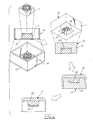
- step (a) involves casting and solidifying a non-fired, low thermally conductive material, such as ceramic 10, about a master pattern 11 to form a ceramic spraying pattern 12.
- the master pattern 11 may be created using solid free-form fabrication techniques controlled by a CAD/CAM model. Free-form fabrication can comprise stereolithography, cubical, laminated or foam object manufacturing, 3-D printing and stratified extrusion. Stereolithography is preferred because it creates a plastic pattern directly from a vat of liquid photo curable polymer through selective solidification using a scanning laser beam. The accuracy of the stereolithography object relative to the computer model is within .01 inches.
- the plastic master pattern 11 is adhered to a base plate 13 of an open box 14 (laminated wood).
- a liquefied ceramic slurry is poured into the box 14 and around master pattern surface.
- the ceramic material used is of the type that requires solidification by heat or freezing to rigidify. If freezing is utilized, the ceramic is dried to a green state and then set by freezing (such as at -30°C to 0°C) for several hours to create a smooth pattern surface.
- a ceramic such as Cotronics Rescor 780TM, containing alumina, or silica core sand, can be used.
- the advantages of using the 780 ceramic are: (i) an excellent surface finish (1-4 microns), (ii) good thermal shock resistance at 1800-2400°F, a compressive strength of at least 9,000 psi, and low shrinkage along with low thermal expansion.
- the solidified ceramic is removed from the master pattern 11 by lifting it free; no particles of the ceramic stick or remain on the master pattern because a release agent is typically applied to the pattern.
- the separated, non-fired ceramic spraying pattern 12 is then heated in an oven to an elevated sustained temperature in the range of 250-500°C, preferably 300°C, the temperature range is selected as one which will obtain an isothermal diffusion-based transformation in the sprayed metal laying on such pattern.
- the selection of the isothermal diffusion temperature is based on the amount of cold work the semi-solid sprayed metal particles will receive as a result of impact with the ceramic pattern.
- This diffusion temperature becomes a low temperature annealing mechanism that provides limited to full recovery for internal stress relief.
- the deposited droplets will be splattered by impact, thereby receiving a moderate degree of cold-work which places them in a state of some mechanical stress with imperfections in the solidifying crystal structure; internal stress is also induced by successive layers of splats shrinking on previous layers. This stress is associated with dislocations which balance internal elastic strains. It is believed that these relatively high energy dislocations will move by a mechanism called "climb" that positions the dislocations in a more energetically favorable position to reduce internal stress substantially.
- Such isothermal temperature must be above the martensitic start temperature for the steel.
- Heating of the ceramic in an oven may be staged, such as by use of a preheat stage at 100-110°C for at least two hours to drive off any remaining water in the ceramic, then gradually ramping up the heating to a temperature of 300°C for about one hour, holding at 300°C for another two hours; then the ceramic is gradually ramped up to about 700°C for five hours to achieve higher densification in certain ceramics, and finally cooled down over a period of several hours (i.e., about 5-7 hours) depending on the thickness of the ceramic, to the targeted isothermal holding temperature (250-500°C) at which it will remain.
- the staged heating cycle may be shortened by eliminating the stage involving heating to 700°C if other ceramics with lower densification can be tolerated.
- the ceramic spraying pattern is removed from the heating oven and inverted to present a pattern surface 35 defining a complex cavity 36 with a cavity depth 37; the pattern 12 is ready to immediately be subjected to thermal spraying.
- thermal spraying guns are utilized to deposit the allotropic metal.
- the thermal spray guns may be of the oxy-acetylene flame type in which a wire or powder metal is fed thereinto, a plasma into which power metal is fed, or preferably one or two wire arc type, in which the tip of the wires is fed into the arc.
- a two wire arc spray gun an electric arc is generated in a zone between two consumable wire electrodes; as the electrodes melt, the arc is maintained by continuously feeding the electrodes into the arc zone.
- the metal at the electrode tips is atomized by a blast of generally cold compressed gas. The atomized metal is then propelled by the gas jet to a substrate forming a deposit thereon.
- a single wire is fed either through the central axis of the torch or is fed at an acute angle into a plasma stream that is generated internally within the torch.
- the single wire acts as a consumable electrode that is fed into the arc chamber.
- An arc is established between the cathode of the plasma torch and the single wire as an anode, thereby melting the tip of the wire.
- Gas is fed into the arc chamber, coaxial to the cathode, where it is expanded by the electric arc to cause a highly heated gas stream (carrying metal droplets from the electrode tip) to flow through the nozzle.
- a further higher temperature gas flow may be used to shroud or surround the spray of molten metal so that the droplets are subjected to further atomization and acceleration.
- wire-arc torch guns may be utilized that use a transferred-arc plasma whereby an initial arc is struck between a cathode and the nozzle surrounding the cathode; the plasma created from such arc is transferred to a secondary anode (outside the gun nozzle) in the form of a single or double wire feedstock causing melting of the tip of such wire feedstock.
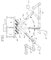
- Thermal spray gun 16 has a gun tip 16a which is oriented along an axis 17 perpendicular to the general planar extent of the exposed surface 35, the tip 16a being arranged generally about 7-14 inches from such exposed surface.
- the spray gun 16 has a power and gas supply 18 operated at a voltage of about 30, a current supply is in the range of 100-250 amps, preferably at about 175 amperes.
- a second gun 19 is carried so that its gun tip 19a is oriented at an angle of about 45° from the first gun axis 17 and has a power and gas supply 20 operated at about 30 volts and at about 100-250 amps, preferably 175 amperes; the gun tip 19a is placed also about 7-14 inches from the exposed surface 35.
- the third spray gun 21 has a gun tip 21a oriented so that its axis 22 is also at a 45° angle with the axis 17 of the first gun and lies in a plane that is generally perpendicular to the plane encompassing guns 16 and 19.
- the third gun has a power and gas supply 23 operated continuously at about 30 volts and a similar current supply of about 100-250 amperes; the gun tip 21a is held at a position of about 7-14 inches from the exposed surface 35.
- Each of the guns is supplied with a high pressure gas from their respective supplies consisting of nitrogen at a pressure of about 40-85 psi; such gas being utilized to effect the atomization of the wire droplets.
- the guns may be moved robotically, such as by robots 24, 25, and the spraying pattern 12 may be mounted on a turntable 26 and rotated by a motor 27 to achieve relative movement between the spray pattern of the guns and the surface 35; repeated passes of the sprayed material will deposit a bulk deposit having a thickness of at least .5 inches on the surface 12.
- the deposit will preferably be in excess of the spraying cavity depth 37, as well as around the sides of spraying pattern box. The excess material at the mouth of the cavity insures dense crystal structures.
- the droplet size of the sprayed metal can be in the range of .01-.10 inches. The droplet size is not believed to be important to the ability to eventually remove stress by the diffusion process of this invention.
- the wire feedstock utilized for each of the guns has a chemistry that consists of steel with carbon in the range of .01-.9% by weight.
- the bulk metal deposit will be essentially devoid of oxides because of the use of a non-oxidizing spray gas, such as nitrogen, and by controlling the spray cell pressure to reduce or prevent aspiration. However, some minor proportion of oxide may creep in due to the entrainment of air about the spray pattern which may be sucked into the spraying chamber if the chamber itself is not flooded with non-oxidizing gases; this should be kept low or eliminated.
- the deposited metal will, by way of heat received from the heated ceramic pattern 12, remain at a temperature at least above the martensite start temperature and generally about the temperature of the ceramic pattern until the diffusion reaction is complete.
- the temperature of the pattern may be maintained at the desired temperature by additionally heating the pattern separate from the furnace so that the temperature may be sustained for one to two hours, if necessary, to achieve completion of the diffusion reaction.
- the temperature an be maintained by changing spray parameters such as current, voltage, spray distance and spray pressure.
- the temperature excursion that is necessary to achieve the stable diffusion reaction is labeled 30.
- the sprayed metal particles 28 contact the pattern surface 35, or the previously deposited particles 29, they are at least partially liquid; they quickly become fully solid at impact or contact.
- the temperature of the particles at impact is estimated to be about 700°-850°C, although no precise measurement has been made.
- the deposited particles drop in temperature quickly (past nose 31 of the diagram represented at 550°C and along excursion line 30 until the temperature of the ceramic spraying pattern is attained (i.e., 300°C). The particles remain at essentially this temperature for a period to allow the metal particles to undergo the diffusion based reaction.
- the time period at which the deposit and ceramic mold must be held at such isothermal temperature will vary from 30 seconds (when the actual isothermal temperature is at about 500°C) to create a coarse bainite, or as long as several hours when the isothermal temperature is at about 280°C to create a fine bainite.
- the time at such temperature also depends on initial cold work of the splats which may drastically reduce this time.
- a significant advantage of the inventive process is that it relieves internal stress when working with a wide range of steel carbon levels. It would be almost impossible to achieve stress relief in a steel having a carbon level of .1-15 weight percent steel by the technique described in the previous Jordan publication because the nose of the TTT diagram is so far shifted to the left, that the metal cannot be coated rapidly enough to obtain martensite (the stress compensation mechanism) and avoid the nose. Thus, Jordan is limited to steel of about .8% carbon to permit the ready formation of martensite.
- the deposited bulk material and pattern are allowed to air cool to room temperature, preferably over a period of about two hours (i.e., 100°C/hour).
- the deposit is separated from the ceramic by cutting with a water jet cutting device which removes essentially all of the deposit outside of cavity 36 along line 38.
- the deposit 39 in the cavity is then separated by chiselling away the ceramic which is relatively fragile.
- the cut bulk deposit may be bead blasted.
- the resulting separated deposit is an exact replica of the starting master pattern and possesses little or no distortion therefrom due to solidification stress concerns.
Landscapes
- Chemical & Material Sciences (AREA)
- Engineering & Computer Science (AREA)
- Mechanical Engineering (AREA)
- Physics & Mathematics (AREA)
- Plasma & Fusion (AREA)
- Chemical Kinetics & Catalysis (AREA)
- Materials Engineering (AREA)
- Metallurgy (AREA)
- Organic Chemistry (AREA)
- Coating By Spraying Or Casting (AREA)
- Other Surface Treatments For Metallic Materials (AREA)
- Moulds For Moulding Plastics Or The Like (AREA)
Applications Claiming Priority (2)
| Application Number | Priority Date | Filing Date | Title |
|---|---|---|---|
| US09/124,779 US5947179A (en) | 1998-07-30 | 1998-07-30 | Sprayforming bulk deposits of allotropic metal |
| US124779 | 1998-07-30 |
Publications (3)
| Publication Number | Publication Date |
|---|---|
| EP0980916A2 true EP0980916A2 (de) | 2000-02-23 |
| EP0980916A3 EP0980916A3 (de) | 2000-04-05 |
| EP0980916B1 EP0980916B1 (de) | 2003-09-03 |
Family
ID=22416754
Family Applications (1)
| Application Number | Title | Priority Date | Filing Date |
|---|---|---|---|
| EP99305886A Expired - Lifetime EP0980916B1 (de) | 1998-07-30 | 1999-07-26 | Spritzformung voluminöser Ablagerungen von allotropen Metall |
Country Status (6)
| Country | Link |
|---|---|
| US (1) | US5947179A (de) |
| EP (1) | EP0980916B1 (de) |
| JP (1) | JP2000064022A (de) |
| CA (1) | CA2278986A1 (de) |
| DE (1) | DE69910922T2 (de) |
| ES (1) | ES2207125T3 (de) |
Cited By (2)
| Publication number | Priority date | Publication date | Assignee | Title |
|---|---|---|---|---|
| GB2343394B (en) * | 1998-11-04 | 2003-06-04 | Ford Motor Co | Method of spray forming readily weldable and machinable machine deposits |
| CN110102751A (zh) * | 2019-04-18 | 2019-08-09 | 电子科技大学 | 金属颗粒抗氧化层等离子体制备技术 |
Families Citing this family (18)
| Publication number | Priority date | Publication date | Assignee | Title |
|---|---|---|---|---|
| US6513567B2 (en) * | 1998-11-04 | 2003-02-04 | Ford Global Technologies, Inc. | Method of making a spray formed rapid tool |
| US6258402B1 (en) * | 1999-10-12 | 2001-07-10 | Nakhleh Hussary | Method for repairing spray-formed steel tooling |
| US6805188B2 (en) * | 2001-04-18 | 2004-10-19 | Ford Global Technologies, Llc | Method and arrangement for heat treatment before the execution of sprayform techniques |
| US6595263B2 (en) * | 2001-08-20 | 2003-07-22 | Ford Global Technologies, Inc. | Method and arrangement for utilizing a psuedo-alloy composite for rapid prototyping and low-volume production tool making by thermal spray form techniques |
| US6904950B2 (en) * | 2001-11-05 | 2005-06-14 | Ford Motor Company | Method and arrangement for affecting time, temperature and transformation dependent stress relief in sprayform techniques |
| US6955209B2 (en) * | 2001-11-05 | 2005-10-18 | Ford Motor Company | Method and arrangement implementing heat treatment after the execution of sprayform techniques |
| US6923241B2 (en) | 2001-11-27 | 2005-08-02 | Ford Motor Company | Method and arrangement for controlling stresses based on one-dimensional modeling in sprayform techniques |
| US6883581B2 (en) * | 2001-11-27 | 2005-04-26 | Ford Motor Company | Method and arrangement for implementing heat treatment during the execution of spray-form techniques |
| US20030196774A1 (en) * | 2001-11-29 | 2003-10-23 | Grigoriy Grinberg | Method to incorporate cooling lines in a spray-formed article |
| US6820677B2 (en) * | 2002-08-20 | 2004-11-23 | Ford Motor Company | Method of making a spray formed article |
| EP3479933A1 (de) | 2009-09-17 | 2019-05-08 | Sciaky Inc. | Vorrichtung zum generativen herstellung mittels elektronenstrahl |
| EP2498935B1 (de) * | 2009-11-13 | 2015-04-15 | Sciaky Inc. | Verfahren zur herstellung eines dreidimensionalen objekts mittels rasterelektronen überwacht mit regelkreis |
| WO2011123195A1 (en) | 2010-03-31 | 2011-10-06 | Sciaky, Inc. | Raster methodology, apparatus and system for electron beam layer manufacturing using closed loop control |
| US9175568B2 (en) | 2010-06-22 | 2015-11-03 | Honeywell International Inc. | Methods for manufacturing turbine components |
| US9085980B2 (en) | 2011-03-04 | 2015-07-21 | Honeywell International Inc. | Methods for repairing turbine components |
| US8506836B2 (en) | 2011-09-16 | 2013-08-13 | Honeywell International Inc. | Methods for manufacturing components from articles formed by additive-manufacturing processes |
| US9266170B2 (en) | 2012-01-27 | 2016-02-23 | Honeywell International Inc. | Multi-material turbine components |
| US9120151B2 (en) | 2012-08-01 | 2015-09-01 | Honeywell International Inc. | Methods for manufacturing titanium aluminide components from articles formed by consolidation processes |
Family Cites Families (9)
| Publication number | Priority date | Publication date | Assignee | Title |
|---|---|---|---|---|
| US4157923A (en) * | 1976-09-13 | 1979-06-12 | Ford Motor Company | Surface alloying and heat treating processes |
| FR2498123A1 (fr) * | 1981-01-19 | 1982-07-23 | Matra | Procede de fabrication de pieces metalliques de forme par projection sur un modele destructible |
| US4957702A (en) * | 1988-04-30 | 1990-09-18 | Qinghua University | Air-cooling duplex bainite-martensite steels |
| US5296667A (en) * | 1990-08-31 | 1994-03-22 | Flame-Spray Industries, Inc. | High velocity electric-arc spray apparatus and method of forming materials |
| US5268018A (en) * | 1991-11-05 | 1993-12-07 | General Electric Company | Controlled process for the production of a spray of atomized metal droplets |
| US5406226A (en) * | 1993-07-07 | 1995-04-11 | Wireless Access, Inc. | Stable, narrow bandwidth, high frequency amplifier with low power consumption |
| GB9419328D0 (en) * | 1994-09-24 | 1994-11-09 | Sprayform Tools & Dies Ltd | Method for controlling the internal stresses in spray deposited articles |
| JP2924664B2 (ja) * | 1994-09-28 | 1999-07-26 | 住友電気工業株式会社 | 微細セラミックス構造体の形成方法 |
| US5658506A (en) * | 1995-12-27 | 1997-08-19 | Ford Global Technologies, Inc. | Methods of making spray formed rapid tools |
-
1998
- 1998-07-30 US US09/124,779 patent/US5947179A/en not_active Expired - Lifetime
-
1999
- 1999-07-21 JP JP11205679A patent/JP2000064022A/ja active Pending
- 1999-07-23 CA CA002278986A patent/CA2278986A1/en not_active Abandoned
- 1999-07-26 ES ES99305886T patent/ES2207125T3/es not_active Expired - Lifetime
- 1999-07-26 EP EP99305886A patent/EP0980916B1/de not_active Expired - Lifetime
- 1999-07-26 DE DE69910922T patent/DE69910922T2/de not_active Expired - Lifetime
Cited By (4)
| Publication number | Priority date | Publication date | Assignee | Title |
|---|---|---|---|---|
| GB2343394B (en) * | 1998-11-04 | 2003-06-04 | Ford Motor Co | Method of spray forming readily weldable and machinable machine deposits |
| DE19943110B4 (de) * | 1998-11-04 | 2005-02-24 | Ford Motor Co., Dearborn | Verfahren zum Spritzformen von leicht schweiß- und bearbeitbaren Metallablagerungen |
| CN110102751A (zh) * | 2019-04-18 | 2019-08-09 | 电子科技大学 | 金属颗粒抗氧化层等离子体制备技术 |
| CN110102751B (zh) * | 2019-04-18 | 2021-04-30 | 电子科技大学 | 金属颗粒抗氧化层等离子体制备技术 |
Also Published As
| Publication number | Publication date |
|---|---|
| US5947179A (en) | 1999-09-07 |
| DE69910922D1 (de) | 2003-10-09 |
| EP0980916A3 (de) | 2000-04-05 |
| JP2000064022A (ja) | 2000-02-29 |
| CA2278986A1 (en) | 2000-01-30 |
| ES2207125T3 (es) | 2004-05-16 |
| DE69910922T2 (de) | 2004-07-22 |
| EP0980916B1 (de) | 2003-09-03 |
Similar Documents
| Publication | Publication Date | Title |
|---|---|---|
| US5947179A (en) | Sprayforming bulk deposits of allotropic metal | |
| US6470954B2 (en) | Method of spray forming readily weldable and machinable metal deposits | |
| KR100305425B1 (ko) | 자유형3차원물품을형성하는방법및장치 | |
| US5658506A (en) | Methods of making spray formed rapid tools | |
| KR19990044218A (ko) | 자유형 3차원 물품을 형성하는 방법 및 장치 | |
| US6949299B2 (en) | Spray formed articles made of boron steel | |
| JP3065305B2 (ja) | 補助加熱を用いた大径溶射成形品の製造方法とそれに用いる装置 | |
| US6155330A (en) | Method of spray forming metal deposits using a metallic spray forming pattern | |
| US6796366B2 (en) | Method for producing a freeze-cast substrate | |
| US5235895A (en) | Ballistic armor and method of producing same | |
| EP1038987B1 (de) | Verfahren zur Verminderung von Verformungen in einem spritzgegossenen Schnellwerkzeug | |
| US6308765B1 (en) | Method of making tools having a core die and a cavity die | |
| US6820677B2 (en) | Method of making a spray formed article | |
| CN107794526A (zh) | 一种激光熔覆和冷喷同步复合的金属零件成形方法 | |
| US6513567B2 (en) | Method of making a spray formed rapid tool | |
| EP0235909B1 (de) | Der Endform nahekommende Schmelzgussfeuerfestprodukte und Verfahren zu ihrer Herstellung durch schnelles Schmelzen und kontrolliertes schnelles Kühlen | |
| US20040191543A1 (en) | Method for enhancing adhesion of metal particles to ceramic models | |
| Fussell et al. | Controlled microstructure of arc-sprayed metal shells | |
| US20050016705A1 (en) | Method and arrangement for an indexing table for making spray-formed high complexity articles | |
| JPH0257141B2 (de) |
Legal Events
| Date | Code | Title | Description |
|---|---|---|---|
| PUAI | Public reference made under article 153(3) epc to a published international application that has entered the european phase |
Free format text: ORIGINAL CODE: 0009012 |
|
| PUAL | Search report despatched |
Free format text: ORIGINAL CODE: 0009013 |
|
| AK | Designated contracting states |
Kind code of ref document: A2 Designated state(s): DE ES GB |
|
| AX | Request for extension of the european patent |
Free format text: AL;LT;LV;MK;RO;SI |
|
| AK | Designated contracting states |
Kind code of ref document: A3 Designated state(s): AT BE CH CY DE DK ES FI FR GB GR IE IT LI LU MC NL PT SE |
|
| AX | Request for extension of the european patent |
Free format text: AL;LT;LV;MK;RO;SI |
|
| 17P | Request for examination filed |
Effective date: 20000826 |
|
| AKX | Designation fees paid |
Free format text: DE ES GB |
|
| 17Q | First examination report despatched |
Effective date: 20020515 |
|
| GRAH | Despatch of communication of intention to grant a patent |
Free format text: ORIGINAL CODE: EPIDOS IGRA |
|
| GRAH | Despatch of communication of intention to grant a patent |
Free format text: ORIGINAL CODE: EPIDOS IGRA |
|
| GRAA | (expected) grant |
Free format text: ORIGINAL CODE: 0009210 |
|
| AK | Designated contracting states |
Kind code of ref document: B1 Designated state(s): DE ES GB |
|
| REG | Reference to a national code |
Ref country code: GB Ref legal event code: FG4D |
|
| REF | Corresponds to: |
Ref document number: 69910922 Country of ref document: DE Date of ref document: 20031009 Kind code of ref document: P |
|
| REG | Reference to a national code |
Ref country code: ES Ref legal event code: FG2A Ref document number: 2207125 Country of ref document: ES Kind code of ref document: T3 |
|
| PLBE | No opposition filed within time limit |
Free format text: ORIGINAL CODE: 0009261 |
|
| STAA | Information on the status of an ep patent application or granted ep patent |
Free format text: STATUS: NO OPPOSITION FILED WITHIN TIME LIMIT |
|
| PGFP | Annual fee paid to national office [announced via postgrant information from national office to epo] |
Ref country code: ES Payment date: 20040716 Year of fee payment: 6 |
|
| 26N | No opposition filed |
Effective date: 20040604 |
|
| REG | Reference to a national code |
Ref country code: GB Ref legal event code: 746 Effective date: 20050126 |
|
| PG25 | Lapsed in a contracting state [announced via postgrant information from national office to epo] |
Ref country code: ES Free format text: LAPSE BECAUSE OF NON-PAYMENT OF DUE FEES Effective date: 20050727 |
|
| REG | Reference to a national code |
Ref country code: ES Ref legal event code: FD2A Effective date: 20050727 |
|
| REG | Reference to a national code |
Ref country code: DE Ref legal event code: R082 Ref document number: 69910922 Country of ref document: DE Representative=s name: DOERFLER, THOMAS, DR.-ING., DE |
|
| PGFP | Annual fee paid to national office [announced via postgrant information from national office to epo] |
Ref country code: DE Payment date: 20180618 Year of fee payment: 20 Ref country code: GB Payment date: 20180625 Year of fee payment: 20 |
|
| REG | Reference to a national code |
Ref country code: DE Ref legal event code: R071 Ref document number: 69910922 Country of ref document: DE |
|
| REG | Reference to a national code |
Ref country code: GB Ref legal event code: PE20 Expiry date: 20190725 |
|
| PG25 | Lapsed in a contracting state [announced via postgrant information from national office to epo] |
Ref country code: GB Free format text: LAPSE BECAUSE OF EXPIRATION OF PROTECTION Effective date: 20190725 |