EP0980920A1 - Dispositif casse-fil dans un ourdissoir pour fils multiples comprenant un dispositif diviseur de fil, un dispositif de réglage de la tension des fils, et un guide pour fil divisé - Google Patents
Dispositif casse-fil dans un ourdissoir pour fils multiples comprenant un dispositif diviseur de fil, un dispositif de réglage de la tension des fils, et un guide pour fil divisé Download PDFInfo
- Publication number
- EP0980920A1 EP0980920A1 EP98115326A EP98115326A EP0980920A1 EP 0980920 A1 EP0980920 A1 EP 0980920A1 EP 98115326 A EP98115326 A EP 98115326A EP 98115326 A EP98115326 A EP 98115326A EP 0980920 A1 EP0980920 A1 EP 0980920A1
- Authority
- EP
- European Patent Office
- Prior art keywords
- thread
- yarn
- divided
- lift
- tension
- Prior art date
- Legal status (The legal status is an assumption and is not a legal conclusion. Google has not performed a legal analysis and makes no representation as to the accuracy of the status listed.)
- Withdrawn
Links
- 230000001174 ascending effect Effects 0.000 claims description 2
- 230000008878 coupling Effects 0.000 claims description 2
- 238000010168 coupling process Methods 0.000 claims description 2
- 238000005859 coupling reaction Methods 0.000 claims description 2
- 238000004804 winding Methods 0.000 abstract description 17
- 238000009941 weaving Methods 0.000 abstract description 10
- 238000000034 method Methods 0.000 abstract description 6
- 230000007547 defect Effects 0.000 abstract description 5
- 230000001276 controlling effect Effects 0.000 description 13
- 238000010276 construction Methods 0.000 description 2
- 239000002184 metal Substances 0.000 description 2
- 229920001875 Ebonite Polymers 0.000 description 1
- 230000002708 enhancing effect Effects 0.000 description 1
- 238000009434 installation Methods 0.000 description 1
- 238000004519 manufacturing process Methods 0.000 description 1
- 239000000463 material Substances 0.000 description 1
- 230000001105 regulatory effect Effects 0.000 description 1
Images



Classifications
-
- D—TEXTILES; PAPER
- D02—YARNS; MECHANICAL FINISHING OF YARNS OR ROPES; WARPING OR BEAMING
- D02H—WARPING, BEAMING OR LEASING
- D02H13/00—Details of machines of the preceding groups
- D02H13/02—Stop motions
- D02H13/04—Stop motions responsive to breakage, slackness, or excessive tension of threads, with detectors for individual threads or small groups of threads
-
- D—TEXTILES; PAPER
- D02—YARNS; MECHANICAL FINISHING OF YARNS OR ROPES; WARPING OR BEAMING
- D02H—WARPING, BEAMING OR LEASING
- D02H13/00—Details of machines of the preceding groups
-
- D—TEXTILES; PAPER
- D02—YARNS; MECHANICAL FINISHING OF YARNS OR ROPES; WARPING OR BEAMING
- D02H—WARPING, BEAMING OR LEASING
- D02H13/00—Details of machines of the preceding groups
- D02H13/02—Stop motions
-
- D—TEXTILES; PAPER
- D02—YARNS; MECHANICAL FINISHING OF YARNS OR ROPES; WARPING OR BEAMING
- D02H—WARPING, BEAMING OR LEASING
- D02H13/00—Details of machines of the preceding groups
- D02H13/16—Reeds, combs, or other devices for determining the spacing of threads
-
- D—TEXTILES; PAPER
- D02—YARNS; MECHANICAL FINISHING OF YARNS OR ROPES; WARPING OR BEAMING
- D02H—WARPING, BEAMING OR LEASING
- D02H13/00—Details of machines of the preceding groups
- D02H13/22—Tensioning devices
- D02H13/26—Tensioning devices for threads in warp form
-
- D—TEXTILES; PAPER
- D02—YARNS; MECHANICAL FINISHING OF YARNS OR ROPES; WARPING OR BEAMING
- D02H—WARPING, BEAMING OR LEASING
- D02H3/00—Warping machines
Definitions
- the present invention generally relates to a divided thread warper for dividing yarn which has a number of pieces of string in a bundle, into a plurality of threads and then winding a desired number of pieces of the divided threads. More particularly, the present invention relates to a device for sensing a snapped thread which includes a device for controlling and providing appropriate yarn tension of a divided thread warper before and after dividing the threads, and a device for guiding the divided thread and for immediate sensing that some pieces of the divided threads have broken and stopping the operations of the yarn feeding section and a winding section, thereby making the division of threads without difficulties and preventing potential defects that may occur during a process for weaving the wound threads.
- yarn having a number of pieces of threads are wound in a plurality of threads and the wound threads are transferred to an area in which a process is performed for weaving a yarn.
- a divided thread warper which includes a plurality of bobbins on which a bundle of yarn having a number of pieces of thread are wound, the bobbins being installed in the yarn feeding section.
- Such a divided thread warper is used to feed the yarn, driving it into a desired number of pieces of thread, for example, 588 pieces of thread, and wind the divided threads on a weaving bobbin in a desired number of pieces of thread.
- such a conventional divided thread warper has disadvantages in that the threads are required to have an appropriate tension externally applied before and after dividing the threads in order to enhance the quality of divided and wound threads, and there is no means for sensing whether a thread(s) has broke due to excessive tension so that in this case the number of pieces of thread is smaller than a predetermined number of pieces are wound on the bobbins, as a result of which a defect is caused in the course of the later weaving process.
- an objective of the present invention is to provide, in a devied thread warper for dividing yarn which has a number of pieces of string in a bundle into a plurality of threads, a device for sensing a snapped thread, which includes a device for controlling yarn tension of a divided thread warper in order to provide the appropriate tension before and after dividing threads, and a device for guiding the divided thread of a divided thread warper for immediate sensing of a the snapped thread and then stopping the operations of a feeding section and a winding section, thereby enabling the division of threads to proceed without difficulties and preventing potential defects that may occur during the process for weaving the woumd threads, twisting the threads in a desired number of pieces of the divided threads.
- the present invention includes a device for controlling yarn tension of a divided thread warper, which has a yarn feeding section provided with a plurality of yarn bobbins, and a yarn dividing section for dividing a yarn unreeled from the yarn feeding section into a plurality of pieces of thread.
- the device is used both before and after the yarn dividing section.
- the device includes driving rollers, which are axially installed on a main/fundamental frame, which are driven by a driving motor.
- a lift frame is installed under the driving rollers, which can be raised or lowered by a lift driving means.
- a pair of loose rollers, axially indtalled in the lift frame and rotating in gear with the driving rollers are used.
- a support frame is fixed to the lift frame and a lift guide plate is attached to the support frame, with thw lift guide plate being guided by a guide rail attached to the fundamental frames and tension controllers
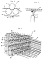
- FIGS. 1-6 illustrate an embodiment of a device for controlling the yarn tension of a divided thread warper.
- the yarn tension controlling device includes a yarn feeding section 20 having a plurality of yarn bobbins 21, a yarn dividing section 30 for dividing the yarn discharged from the yarn feeding section 20 into a plurality of threads, and tension controllers 10 and 10' installed before and after the yarn dividing section 30.
- tension controllers 10 and 10' illustrated in FIG. 1 are of the same construction.
- driving rollers 12 and 12' which are driven by a driving motor M, are axially fixed to fundamental frames 11 and 11'.
- a lift frame 16 is installed under the driving rollers 12 and 12' and is moved up and down by means of a lift driver 17.
- Lift guide plates 15 and 15' which are guided by a guide rail 15a formed in the fundamental frames 11 and 11', are attached to a support frame 14.
- Support frame 14 is attached to the lift frame 16, as illustrated in FIG. 3.
- the driving rollers 12 and 12' are metal rollers whose surfaces are smooth and the loose rollers 13 and 13' are coated with a hard rubber material which is somewhat elastic and resistant to wear so that a thread A' can be transferred easily and provided with a tension.
- the driving rollers 12 and 12' are combined in engagement with the driving motor M by a belt B and a pulley C, to which the construction the present invention is not specifically limited and the driving rollers 12 and 12' may be combined in engagement with the driving motor by a chain or sprocket.
- the lift driver 17 comprises a lift driving motor M', a decelerator 18, a driving screw 19 connected to the axis of the decelerator 18, and a driving nut 19' which engages the driving screw 19.
- the driving nut 19' is fixedly coupled to the lower surface of the lift frame 16.
- the lift driving motor M' makes a clockwise or counterclockwise rotation under the control of a controller (not shown) according to dividing or winding threads.
- the lift guide plate 15 is fixedly attached to the fundamental frames 11 and 11' by means of a mounting plate 14, which is installed on one side of the lift guide plate 15.
- the guide rail 15a and the lift guide plate 15 are provided in form of a triangle notch, as see FIG. 5.
- the guide rail 15a and the lift guide plate 15 may be in the dovetail form.
- Reference symbol A' represents a divided or wound thread of the present invention
- reference numeral 40 indicates a winding section for twisting the divided thread A' by a predetermined number of pieces of thread and winding the same.
- a yarn having a bundle of threads is unreeled from the yarn bobbin 21 which is installed in the yarn feeding section 20, divided through the yarn dividing section 30, and wound on a weaving bobbin (not shown) of a winding section 40.
- the thread A' is first provided with tension by the tension controller 10 which is installed between the yarn feeding section 20 and the yarn dividing section 30. Passing through the yarn dividing section 30, the thread A' is again provided with tension by a tension controller 10' installed between the yarn dividing section 30 and the winding section 40, before it is wound.
- the loose rollers 13 and 13' are moved with respect to the driving roller 12 which is rotating at a fixed position on the fundamental frame 11, thereby adjusting the contact pressure for the driving roller 12, which controls the tension of the thread A' passing between the driving roller 12 and the loose rollers 13 and 13'.
- the entire tension of the thread A' can also be controlled by varying the extent of engagement of rollers 13, 13' with roller 12 of the transferring the thread A' from the tension controllers 10 and 10' each of which is installed on either side of the yarn dividing section 30.
- FIG. 7 illustrates another preferred embodiment of a yarn tension controlling device of a divided thread warper, wherein the lift driver 17 is an oil pressure cylinder S which is fixedly connected to the lower surface of the lift frame 16 at the top of the rod R.
- the cylinder S is associated with an oil pressure system which is under the control of a controller and moves the lift frame 16 up and down while the rod R is ascending and descending.
- the other components are identical to those of the previously described embodiment. Therefore, the same reference numeral denotes the same component and will be omitted in the description.
- FIGS. 8-10 illustrate a snapped thread sensing device provided with a divided thread guiding device of a divided thread warper in accordance with a preferred embodiment of the present invention.
- FIG. 8 is an enlarged perspective view illustrating the principal part of the yarn dividing section 30 for dividing a yarn unreeled from the yarn feeding section 20 into a plurality of pieces of thread.
- a plurality of bases 22 and support rods 23 are installed in the perpendicular and/or horizontal direction in a rectangular frame 31.
- Each space defined by the bases 22 and the support rods 23 includes a plurality of thread guiding pieces 26 having a thread guiding ring 26' for guiding the dividing thread.
- the thread guiding pieces 26 are associated with a switch operating piece 24' of a machine operating switch 24 in order to operate the machine operating switch 24.
- the switch operating piece 24' of the machine operating switch 24 and the thread guiding pieces 26 are installed in the direction where the thread guiding rings 26' are upwardly inclined, so that the switch operating piece 24' is continually pressed by the tension of thread thereby holding in an "on” position the machine operating switch 24 while the divided thread A is travelling therethrough, and if the travelling thread A is snapped off, the switching operating piece 24' reverts to its upward "off” opsition due to an elastic force applied thereto.
- the machine operating switch 24 is electrically connected to the driving motor M of the yarn feeding section 20 and the first and second tension controller 10 and 10'. While the tension of the divided thread A is imposed upon the thread guiding pieces 26, the machine operating switch 24 connects the power supply to the driving motor M. If the thread A is snapped off and no tension is imposed upon the thread guiding pieces 26, the power supply to the driving motor M is interrupted by the machine operating switch 24.
- the switch operating piece 24' of the machine operating switch 24 can be associated with the thread guiding pieces 26 in a direction manner. However, it is more preferable for easier fabrication that the switch operating piece 24' and the thread guiding pieces 26 are associated with each other by means of a coupling piece 25 which has fitting and fastening structures made of a conductive metal on both ends.
- Reference numeral 50 in FIG. 1 indicates a support foot for supporting the rectangular frame
- reference numerals 27 and 27' indicate an interval controller for regulating the interval from before the thread passes through a dividing port immediately after passing through the first tension controller 10 to before the thread passes through the second tension controller 10'.
- an interval controller 27 is positioned before the first tension controller 10. As illustrated in FIG. 9, the interval controller is comb-shaped in order to make the divided thread A travelling in a straight line and passing through the second tension controller 10' at a predetermined distance from it.
- the snapped thread sensing device provided with a divided thread guiding device as constructed above, unreels a yarn having a plurality of pieces of thread in a bundle from the yarn bobbin 21 which is installed in the yarn feeding section 20, divides the yarn into a plurality of pieces of thread A' through the thread guide rings 26' of the thread guide pieces 26, and winds the threads A' on the weaving bobbin (not shown) of the winding section 40 shown in FIG. 1.
- first tension is imposed upon the thread A' by the first tension controller 10 of FIG. 1 installed between the yarn feeding section 20 and the yarn dividing section 30.
- the thread A is provided with second tension by the second tension controller 10' before it is divided and wound.
- the divided thread A passes through the second tension controller 10' at predetermined intervals by means of an interval controller 27 which is installed between the yarn dividing section 30 and the driving roller 12' of the second tension controller 10'.
- the thread guiding pieces 26 is pressed down by the tension imposed upon the thread A, thereby maintaining the switch operating piece 24' of the machine operating switch 24 associated with the thread guiding pieces 26,i.e., holding the machine operating switch 24 in an "on" position.
- the power is applied to the driving motors of the yarn feeding section 20 and the tension controllers 10 and 10'.
- the thread A which is divided and wound under a tension provided by the first and second tension controllers 10 and 10' in FIG. 1 is wound at a high speed of several hundreds of meters per minute.
- a piece of thread A is snapped off in such a dividing and winding step, no tension is imposed upon the thread guiding pieces 26 that guide the thread A so that the switch operating piece 24' returns its biased "off" position(by some tensioning means such as elastic), turning off the machine operating switch 24.
- FIG. 8 is an enlarged perspective view illustrating the principal part of a snapped thread sensing device having a divided thread guiding device in accordance with the present invention, wherein the thread A guided by the two thread guiding pieces 26 is snapped off on the left top side.
- the tension of the thread is controlled before and after the yarn dividing section, enhancing the quality of the divided and wound threads. Furthermore, if even a piece of the divided thread is snapped off, the driving motors of the yarn feeding section, the tension controllers, and the winding section are suspended immediately, whereby it is possible to avoid the potential defect in the subsequent weaving process.
Landscapes
- Engineering & Computer Science (AREA)
- Textile Engineering (AREA)
- Looms (AREA)
Priority Applications (1)
| Application Number | Priority Date | Filing Date | Title |
|---|---|---|---|
| EP98115326A EP0980920A1 (fr) | 1998-08-14 | 1998-08-14 | Dispositif casse-fil dans un ourdissoir pour fils multiples comprenant un dispositif diviseur de fil, un dispositif de réglage de la tension des fils, et un guide pour fil divisé |
Applications Claiming Priority (1)
| Application Number | Priority Date | Filing Date | Title |
|---|---|---|---|
| EP98115326A EP0980920A1 (fr) | 1998-08-14 | 1998-08-14 | Dispositif casse-fil dans un ourdissoir pour fils multiples comprenant un dispositif diviseur de fil, un dispositif de réglage de la tension des fils, et un guide pour fil divisé |
Publications (1)
| Publication Number | Publication Date |
|---|---|
| EP0980920A1 true EP0980920A1 (fr) | 2000-02-23 |
Family
ID=8232460
Family Applications (1)
| Application Number | Title | Priority Date | Filing Date |
|---|---|---|---|
| EP98115326A Withdrawn EP0980920A1 (fr) | 1998-08-14 | 1998-08-14 | Dispositif casse-fil dans un ourdissoir pour fils multiples comprenant un dispositif diviseur de fil, un dispositif de réglage de la tension des fils, et un guide pour fil divisé |
Country Status (1)
| Country | Link |
|---|---|
| EP (1) | EP0980920A1 (fr) |
Cited By (8)
| Publication number | Priority date | Publication date | Assignee | Title |
|---|---|---|---|---|
| WO2012171836A1 (fr) * | 2011-06-11 | 2012-12-20 | Trützschler Nonwovens Gmbh | Mécanisme de traction pour le transport de filaments |
| CN103046191A (zh) * | 2012-12-28 | 2013-04-17 | 苏州焕乾纺织有限公司 | 用于纱线直径调节的伸缩筘机构 |
| CN104389067A (zh) * | 2014-12-08 | 2015-03-04 | 李雪明 | 整经机 |
| CN107447321A (zh) * | 2017-10-12 | 2017-12-08 | 湖州恒新商标制带有限公司 | 锦纶母纱整经方法及锦纶母纱整经装置 |
| CN108708028A (zh) * | 2018-04-22 | 2018-10-26 | 通城县同力玻纤有限公司 | 一种玻璃纤维一次性高速整经的生产方法 |
| CN110230139A (zh) * | 2019-04-09 | 2019-09-13 | 广东天海花边有限公司 | 一种对膜片纱线整经的花轴整经机 |
| CN112299146A (zh) * | 2019-07-30 | 2021-02-02 | 日本Tmt机械株式会社 | 合成纤维纱用接头系统 |
| CN114808230A (zh) * | 2022-03-31 | 2022-07-29 | 浙江理工大学 | 一种用于整经机断线对接的智能接头装置 |
Citations (6)
| Publication number | Priority date | Publication date | Assignee | Title |
|---|---|---|---|---|
| US3678548A (en) * | 1970-11-12 | 1972-07-25 | Lorraine De Preparation Textil | Leasing apparatus and method |
| EP0152919A2 (fr) * | 1984-02-18 | 1985-08-28 | B a r m a g AG | Appareil pour l'entrelacement par jet d'air d'une multiplicité de fils en mouvement |
| EP0263223A1 (fr) * | 1986-10-06 | 1988-04-13 | Industrial Processes And Research B.V. | Procédé et dispositif de fabrication de bobines remplies de fil de trame teint à l'indigo |
| US4850086A (en) * | 1988-05-27 | 1989-07-25 | Reed-Chatwood, Inc. | Warper with ironing rolls |
| EP0365471A1 (fr) * | 1988-10-19 | 1990-04-25 | Benninger AG | Dispositif de contrôle de fil de trame pour machine textile |
| JPH0748745A (ja) * | 1993-08-06 | 1995-02-21 | Asahi Shiyueebell Kk | エキスパンションアイボード |
-
1998
- 1998-08-14 EP EP98115326A patent/EP0980920A1/fr not_active Withdrawn
Patent Citations (6)
| Publication number | Priority date | Publication date | Assignee | Title |
|---|---|---|---|---|
| US3678548A (en) * | 1970-11-12 | 1972-07-25 | Lorraine De Preparation Textil | Leasing apparatus and method |
| EP0152919A2 (fr) * | 1984-02-18 | 1985-08-28 | B a r m a g AG | Appareil pour l'entrelacement par jet d'air d'une multiplicité de fils en mouvement |
| EP0263223A1 (fr) * | 1986-10-06 | 1988-04-13 | Industrial Processes And Research B.V. | Procédé et dispositif de fabrication de bobines remplies de fil de trame teint à l'indigo |
| US4850086A (en) * | 1988-05-27 | 1989-07-25 | Reed-Chatwood, Inc. | Warper with ironing rolls |
| EP0365471A1 (fr) * | 1988-10-19 | 1990-04-25 | Benninger AG | Dispositif de contrôle de fil de trame pour machine textile |
| JPH0748745A (ja) * | 1993-08-06 | 1995-02-21 | Asahi Shiyueebell Kk | エキスパンションアイボード |
Non-Patent Citations (1)
| Title |
|---|
| PATENT ABSTRACTS OF JAPAN vol. 095, no. 005 30 June 1995 (1995-06-30) * |
Cited By (13)
| Publication number | Priority date | Publication date | Assignee | Title |
|---|---|---|---|---|
| CN103635406A (zh) * | 2011-06-11 | 2014-03-12 | 特吕茨勒非织造布有限公司 | 用于输送长丝的张紧装置 |
| CN103635406B (zh) * | 2011-06-11 | 2016-10-19 | 欧瑞康纺织有限及两合公司 | 用于输送长丝的张紧装置 |
| WO2012171836A1 (fr) * | 2011-06-11 | 2012-12-20 | Trützschler Nonwovens Gmbh | Mécanisme de traction pour le transport de filaments |
| CN103046191A (zh) * | 2012-12-28 | 2013-04-17 | 苏州焕乾纺织有限公司 | 用于纱线直径调节的伸缩筘机构 |
| CN104389067A (zh) * | 2014-12-08 | 2015-03-04 | 李雪明 | 整经机 |
| CN107447321B (zh) * | 2017-10-12 | 2019-09-17 | 湖州恒新商标制带有限公司 | 锦纶母纱整经方法及锦纶母纱整经装置 |
| CN107447321A (zh) * | 2017-10-12 | 2017-12-08 | 湖州恒新商标制带有限公司 | 锦纶母纱整经方法及锦纶母纱整经装置 |
| CN108708028A (zh) * | 2018-04-22 | 2018-10-26 | 通城县同力玻纤有限公司 | 一种玻璃纤维一次性高速整经的生产方法 |
| CN108708028B (zh) * | 2018-04-22 | 2024-04-09 | 通城县同力玻纤有限公司 | 一种玻璃纤维一次性高速整经的生产方法 |
| CN110230139A (zh) * | 2019-04-09 | 2019-09-13 | 广东天海花边有限公司 | 一种对膜片纱线整经的花轴整经机 |
| CN112299146A (zh) * | 2019-07-30 | 2021-02-02 | 日本Tmt机械株式会社 | 合成纤维纱用接头系统 |
| CN112299146B (zh) * | 2019-07-30 | 2024-05-31 | 日本Tmt机械株式会社 | 合成纤维纱用接头系统 |
| CN114808230A (zh) * | 2022-03-31 | 2022-07-29 | 浙江理工大学 | 一种用于整经机断线对接的智能接头装置 |
Similar Documents
| Publication | Publication Date | Title |
|---|---|---|
| EP0980920A1 (fr) | Dispositif casse-fil dans un ourdissoir pour fils multiples comprenant un dispositif diviseur de fil, un dispositif de réglage de la tension des fils, et un guide pour fil divisé | |
| ITTO940577A1 (it) | Dispositivo per la regolazione della tensione di un filo. | |
| EP1342686B1 (fr) | Dispositif de guidage d'un fil pour des métiers à filer à bout libre | |
| PT1156143E (pt) | Processo para o accionamento de esquinadeiras de canelas e esquinadeira para uma instalacao de enrolamento | |
| CN1204032C (zh) | 纱线退绕张力稳定器及用于整经筒子架的纱线退绕张力稳定装置 | |
| CN101078147A (zh) | 利用步进马达的分丝卷绕机驱动装置 | |
| KR20090010772A (ko) | 빔 탈착이 용이한 권취기 | |
| JPH07227840A (ja) | プリプレグの製造装置および製造方法 | |
| CN1094008A (zh) | 用于纺织机上的纱线络纱方法以及实施此方法的机器 | |
| CN1872647A (zh) | 生产交叉卷绕筒子的纺织机的卷绕机构的纱线横动装置 | |
| KR100996406B1 (ko) | 연속소선공급장치 및 방법 | |
| KR100445290B1 (ko) | 정경 와인더 | |
| CN102146614A (zh) | 一种编织机 | |
| JP4088853B2 (ja) | 解舒装置 | |
| ITRM20070043A1 (it) | Macchina per orditura automatica a campioni con sistema automatizzato multifilo e relativo metodo. | |
| CN224198934U (zh) | 一种空调连接线加工剪切设备 | |
| US822278A (en) | Jack or dresser spooling machine. | |
| KR200201031Y1 (ko) | 커버링 머신용 피복사 장력 조절구조 | |
| CN117468161B (zh) | 应用于全幅衬纬经编机的送纬装置 | |
| US20080163470A1 (en) | Thread accumulation device | |
| KR0133643Y1 (ko) | 전자총의 s-링 공급장치 | |
| KR200221324Y1 (ko) | 연선기의 스풀 역회전 방지장치 | |
| KR19990025412U (ko) | 권선기의 와이어 장력 조절장치 | |
| KR910005537B1 (ko) | 와이어 연선기의 연선장치 | |
| CN110510455A (zh) | 一种压丝辊机架及压丝装置 |
Legal Events
| Date | Code | Title | Description |
|---|---|---|---|
| PUAI | Public reference made under article 153(3) epc to a published international application that has entered the european phase |
Free format text: ORIGINAL CODE: 0009012 |
|
| AK | Designated contracting states |
Kind code of ref document: A1 Designated state(s): CH DE ES FR IT LI |
|
| AX | Request for extension of the european patent |
Free format text: AL;LT;LV;MK;RO;SI |
|
| 17P | Request for examination filed |
Effective date: 20000822 |
|
| AKX | Designation fees paid |
Free format text: CH DE ES FR IT LI |
|
| 17Q | First examination report despatched |
Effective date: 20020806 |
|
| STAA | Information on the status of an ep patent application or granted ep patent |
Free format text: STATUS: THE APPLICATION IS DEEMED TO BE WITHDRAWN |
|
| 18D | Application deemed to be withdrawn |
Effective date: 20030217 |