EP0980942B1 - Caniveau d'écoulement - Google Patents
Caniveau d'écoulement Download PDFInfo
- Publication number
- EP0980942B1 EP0980942B1 EP99115912A EP99115912A EP0980942B1 EP 0980942 B1 EP0980942 B1 EP 0980942B1 EP 99115912 A EP99115912 A EP 99115912A EP 99115912 A EP99115912 A EP 99115912A EP 0980942 B1 EP0980942 B1 EP 0980942B1
- Authority
- EP
- European Patent Office
- Prior art keywords
- drainage channel
- drainage
- height adjustment
- channel according
- shape
- Prior art date
- Legal status (The legal status is an assumption and is not a legal conclusion. Google has not performed a legal analysis and makes no representation as to the accuracy of the status listed.)
- Expired - Lifetime
Links
- 239000002184 metal Substances 0.000 claims abstract description 4
- 229910052751 metal Inorganic materials 0.000 claims abstract description 4
- 239000010935 stainless steel Substances 0.000 claims description 6
- 229910001220 stainless steel Inorganic materials 0.000 claims description 5
- 229910000831 Steel Inorganic materials 0.000 claims description 4
- 239000010959 steel Substances 0.000 claims description 4
- 238000003780 insertion Methods 0.000 description 13
- 230000037431 insertion Effects 0.000 description 13
- 239000002352 surface water Substances 0.000 description 5
- 238000010276 construction Methods 0.000 description 4
- 230000000694 effects Effects 0.000 description 2
- 239000000463 material Substances 0.000 description 2
- 230000003287 optical effect Effects 0.000 description 2
- 239000000126 substance Substances 0.000 description 2
- XLYOFNOQVPJJNP-UHFFFAOYSA-N water Substances O XLYOFNOQVPJJNP-UHFFFAOYSA-N 0.000 description 2
- RYGMFSIKBFXOCR-UHFFFAOYSA-N Copper Chemical compound [Cu] RYGMFSIKBFXOCR-UHFFFAOYSA-N 0.000 description 1
- 239000010426 asphalt Substances 0.000 description 1
- 238000005452 bending Methods 0.000 description 1
- 230000000903 blocking effect Effects 0.000 description 1
- 238000004140 cleaning Methods 0.000 description 1
- 208000027744 congestion Diseases 0.000 description 1
- 229910052802 copper Inorganic materials 0.000 description 1
- 239000010949 copper Substances 0.000 description 1
- 229920001971 elastomer Polymers 0.000 description 1
- 238000009434 installation Methods 0.000 description 1
- JEIPFZHSYJVQDO-UHFFFAOYSA-N iron(III) oxide Inorganic materials O=[Fe]O[Fe]=O JEIPFZHSYJVQDO-UHFFFAOYSA-N 0.000 description 1
- 230000007774 longterm Effects 0.000 description 1
- 238000012423 maintenance Methods 0.000 description 1
- 229920003023 plastic Polymers 0.000 description 1
- 229920001084 poly(chloroprene) Polymers 0.000 description 1
- 238000007789 sealing Methods 0.000 description 1
- 239000002699 waste material Substances 0.000 description 1
- 238000003466 welding Methods 0.000 description 1
Images




Classifications
-
- E—FIXED CONSTRUCTIONS
- E03—WATER SUPPLY; SEWERAGE
- E03F—SEWERS; CESSPOOLS
- E03F3/00—Sewer pipe-line systems
- E03F3/04—Pipes or fittings specially adapted to sewers
- E03F3/046—Open sewage channels
-
- E—FIXED CONSTRUCTIONS
- E04—BUILDING
- E04D—ROOF COVERINGS; SKY-LIGHTS; GUTTERS; ROOF-WORKING TOOLS
- E04D13/00—Special arrangements or devices in connection with roof coverings; Protection against birds; Roof drainage ; Sky-lights
- E04D13/04—Roof drainage; Drainage fittings in flat roofs, balconies or the like
- E04D13/0404—Drainage on the roof surface
- E04D13/0445—Drainage channels
-
- E—FIXED CONSTRUCTIONS
- E03—WATER SUPPLY; SEWERAGE
- E03F—SEWERS; CESSPOOLS
- E03F5/00—Sewerage structures
- E03F5/04—Gullies inlets, road sinks, floor drains with or without odour seals or sediment traps
- E03F2005/0412—Gullies inlets, road sinks, floor drains with or without odour seals or sediment traps with means for adjusting their position with respect to the surrounding surface
- E03F2005/0413—Gullies inlets, road sinks, floor drains with or without odour seals or sediment traps with means for adjusting their position with respect to the surrounding surface for height adjustment
Definitions
- the present invention relates to a Drainage channel made of metal, preferably made of Stainless steel or galvanized sheet steel, in particular from Armco Sendzimir galvanized Sheet steel, with a substantially U-shaped Cross section, in the area of the U-web and / or in Area of the two U-legs drain openings are punched out, the two U-legs across, preferably at right angles, to the outside as a support are bent for at least one grate and to the two U-legs height adjustment devices are attached.
- a Drainage channel made of metal, preferably made of Stainless steel or galvanized sheet steel, in particular from Armco Sendzimir galvanized Sheet steel, with a substantially U-shaped Cross section, in the area of the U-web and / or in Area of the two U-legs drain openings are punched out, the two U-legs across, preferably at right angles, to the outside as a support are bent for at least one grate and to the two U-legs height adjustment devices are attached.
- Such drainage channels are used for facades, Flat roofs, green roofs, patios or the like used to drain surface water.
- Around the drainage channels to the water level of the Making surface water adaptable is at conventional drainage channels one Height adjustment device for the storage of the Drainage channels provided.
- Such height adjustment devices are in turn in the form of known drainage channels adjustable screw feet executed on the Drainage channels are permanently attached. At the Cutting prefabricated drainage channels to length dimensions required in practice, for example about 1,000 millimeters or about 1,500 millimeters it turned out to be extremely disadvantageous, that the fixed height adjustment devices not adaptable to the dimensions of the drainage channels are.
- a drainage channel is known (DE 32 14 442 C2) for with a water-permeable covering provided flat roofs, consisting of one in this Cover provided groove-shaped recess that by one on a height-adjustable support arranged rust covered and covered by water-permeable side boundary walls is stiffened, the support from two in Angular profiles kept apart consists of the protruding legs of im Distance from each other, in cross section U-shaped brackets at the desired height are set, and being the side Boundary walls through on the outside of this Legs arranged pinhole are formed.
- the protruding legs of the cross section U-shaped brackets have slot-like recesses through which screws extend which lead to the Set the angle profiles in the desired one Serve at high altitude, with the grille on the Angle profiles using a clamp bracket is set.
- the well-known system for height adjustment has proven itself insofar as not unproblematic in that it doesn't the dimensions of the drainage channels can be adjusted so that the well-known drainage channel, for example depending on the respective spatial Conditions flexibly and individually adjustable is.
- Drainage channels are in accordance with the present invention based on the task of a drainage channel for To make available at which the Height adjustment devices can be released in a simple manner attached and to the grid of the drain openings can be adjusted.
- This task is accomplished through a drainage channel according to the preamble of the main claim by its characteristic features according to the invention solved that the height adjustment on the Drainage channel detachable using at least one Plug connection can be determined via insertion holes and that the insertion holes in a given Grids are arranged along the drainage channel.
- the drainage channels that can be cut to length according to the invention are of substantially U-shaped cross-section Sheets, for example made of corrosion-resistant Steel sheets or made of high quality stainless Stainless steel sheets made to long-term Ensure functionality.
- U-bridge or the two U-legs preferably as elongated holes in Trained longitudinal direction of the drainage channel Drain openings punched in, which lead to a removal of the in entering the drainage channel Cause surface water.
- the for example, nose-shaped supports serve in this context as a safeguard for that the grate lies securely and immovably.
- the drain openings are preferably according to one certain grid arranged on the U-webs what regarding a cut to the length of the building necessary measure proves to be appropriate.
- the Height adjustment devices using at least one Detachable and relocatable plug connection to the U-legs can be fixed. Even with extreme ones Bumps and / or obstacles as well as on site cut pieces can therefore be cut Height adjustment. at intervals of for example, about a hundred millimeters with just move two simple steps; it there is practically no waste, because the Remnants can be reused.
- the height adjustment device in a thread is particularly preferred on that in operative connection with the respective Adjustment head or with the respective adjustment screw can stand and by rotating the respective Adjustment head or the respective adjustment screw with a conventional screwdriver Height adjustment device and thus the Drainage channel changed continuously and to the be adapted to local conditions can.
- the drainage channel is always piece for
- the height of the piece can be flexibly adjusted so that for example when an adjacent one settles Roof structure without problems even after years Disassembly of the aforementioned grate types readjusted can be.
- the drainage channel by means of the insertion holes in an expedient manner adjustable in the longitudinal direction.
- the foot part of the Height adjustment device and / or the support according to a particularly preferred embodiment of the present invention from an envelope non-slip material, e.g. plastic, such as rubber or neoprene.
- an envelope non-slip material e.g. plastic, such as rubber or neoprene.
- drainage channel is particularly preferred Ways to be further developed are not just those Insertion holes, but also the adjustment openings and, if necessary, also for the incoming Drainage openings provided in a water predetermined grid along the drainage channel arranged.
- At least one of the two ends of the U-web to provide at least one notch in which a preferably double U-shaped connecting element for Connecting two drainage channels is insertable or on which a preferably double U-shaped Connecting element for connecting two Drainage channels can be plugged on.
- the drainage channels are already at the channel joint with the basic orientation in the horizontal direction and stabilized in the vertical direction, one aligned, bend and torsion-free as well as quick laying of the drainage channel is guaranteed, depending on the track length the construction work by about Double to triple increase; this saves time and especially high labor costs, being the assembly due to the simplicity and clarity of the system presented here also for unskilled Auxiliary staff rationally and without any problems is feasible.
- the insertion holes for the height adjustment devices are preferably as vertical slots trained in the locking hooks attached to the Height adjustment devices are attached, can intervene.
- the locking hook after insertion into the vertical slots Locking tabs that go into the locking hook can be introduced and intervene in them lock.
- the drainage channel can not only be in the form of a straight, not curved part. Depending on the structural conditions, but also of design preferences Drainage channel in an advantageous manner Form of a preferably rectangular corner piece with for example five or six Height adjustment devices and / or in the form of a T-piece and / or in the form of a cross piece be trained.
- an end cap or a bumper to attach to the end of the drainage channel to provide adequate completion of the Form drainage channel.
- the present drainage channel is at least one end of the drainage channel to at least one breakout outlet, preferably rectangular, especially roughly square as a terrace kit trained gully box laterally offset and / or connectable in the middle.
- a breakout outlet preferably rectangular, especially roughly square as a terrace kit trained gully box laterally offset and / or connectable in the middle.
- a Slot drainage with the usual gully sizes corresponding recesses.
- the Terrace kit the height of which is essentially should correspond to the drainage channel, one four-sided connection possibility, which as a departure trained connection openings as a result of Pretreatment, for example using a Laser beam, in a particularly simple manner must be broken out.
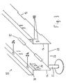
- the cut-to-length drainage channel 10 which in the Figures 1, 2 and 3 in sections and in the Figures 6 and 7 is shown in full length and the in longitudinal form, in the form of a particular right-angled corner piece and also in the form of a T-piece or a cross piece can, contains grid-like stamped, as Elongated holes in the longitudinal direction of the drainage channel 10 formed drain openings 12 (see FIGS. 1, 3, 6 and 7), which a removal of the in the Drainage channel 10 incoming surface water cause.
- the two U-legs 14 of the drainage channel 10 have supports running at right angles to the outside 16 on (see FIGS. 1, 3, 6, 7 and 8), on the a grate 20 can be placed (see FIGS. 1 and 2) that covers the drainage channel 10 and that Intrusion of leaves, dirt or other that Drain openings 12 potentially clogging substances prevented.
- the supports 16 serve in this Connection as a guarantee that the grate 20 lies securely and immovably.
- Insertion holes 18 are provided on the U-legs 14 in grid-like intervals Insertion holes 18 (see FIGS. 1, 2, 3 and 7) for the height adjustment devices 22 (cf. the Figures 2, 3, 4, 6, 7 and 8) are provided. Farther are in the area of the insertion holes 18th Adjustment openings 24 provided, the Insertion holes 18 and the adjustment openings 24 in a predetermined grid along the Drainage channel 10 are arranged (see Figures 1 and 3).
- Height adjustment device 22 is therefore in contrast convenient to conventional drainage channels, easily and easily accessible from above without Parts of the drainage channel 10 are dismantled would have to, because the respective adjustment head 38 or respective adjustment screw 38 (see FIG. 6) is also unhindered by the openings of gratings 20 or parallel gratings 20 accessible.
- the Height adjustment device 22 among other things Thread 36 on that in operative connection with the respective adjustment head 38 or with the respective Adjusting screw 38 (see FIG. 6) stands and through that when turning the respective adjustment head 38 or the respective adjusting screw 38 with a conventional screwdriver the amount of Height adjustment device 22 and thus the Drainage channel 10 continuously changed and to the is adapted to local conditions.
- the drainage channel 10 is always a piece the height of pieces can be flexibly adjusted so that for example when an adjacent one settles Roof structure without problems even after years Disassembly of the aforementioned grate types 20 readjusted can be. Furthermore, the drainage channel 10 by means of the insertion holes 18 also in Adjustable lengthwise.
- Insertion holes 18 can be used as vertical slots be formed (see FIGS. 1, 2, 3 and 7), in which engage the locking hooks 32.
- notches 26 are provided (see FIGS. 1 and 3) used to connect multiple Drainage channels 10 serve. These notches 26 can by double U-shaped connecting elements 30 are connected (see FIG. 5), which in the respective Notch 26 can be inserted or on the each notch 26 can be plugged.
- the drainage channel 10 is not with a another drainage channel 10 or with another Drainage component should be connected, but to be used as a closing element, for example at the end of a facade, one Flat roof, a green roof, a terrace or the like, instead of the connecting element 30 an end cap or a bumper plate to attach to Provide end of the drainage channel 10.
- a closing element for example at the end of a facade, one Flat roof, a green roof, a terrace or the like
- the end of the Drainage channel 10 also to a breakaway Leaving one in particular approximately as a square Terrace kit of trained gully box on the side offset and / or connected in the middle.
Landscapes
- Engineering & Computer Science (AREA)
- Architecture (AREA)
- Structural Engineering (AREA)
- Hydrology & Water Resources (AREA)
- Public Health (AREA)
- Water Supply & Treatment (AREA)
- Health & Medical Sciences (AREA)
- Civil Engineering (AREA)
- Life Sciences & Earth Sciences (AREA)
- Sink And Installation For Waste Water (AREA)
- Sewage (AREA)
- External Artificial Organs (AREA)
- Liquid Developers In Electrophotography (AREA)
- Coating With Molten Metal (AREA)
- Bridges Or Land Bridges (AREA)
Claims (10)
- Caniveau d'évacuation des eaux (10), en métal, de préférence en acier
inoxydable ou en tôle d'acier galvanisée, en particulier en tôle d'acier galvanisée par le procédé Armco-Sendzimir, possédant une section transversale sensiblement en forme de U, dans lequelcaractérisé en ce quedes ouvertures d'écoulement (12) sont découpées dans la région de l'âme (28) du U et/ou dans la région des deux branches (14) du U,les deux branches (14) du U sont repliées transversalement, de préférence perpendiculairement, vers l'extérieur pour constituer des appuis (16) pour au moins une grille (20) etdes dispositifs de réglage en hauteur (22) sont disposés sur les deux branches (14) du U,
les dispositifs de réglage en hauteur (22) peuvent être fixés sur le caniveau d'évacuation des eaux (10) de façon démontable au moyen d'au moins un assemblage à emboítement, par l'intermédiaire de trous d'emboítement (18) et en ce que, les trous d'emboítement (18) sont disposés dans un motif prédéterminé le long du caniveau d'évacuation des eaux (10). - Caniveau d'évacuation des eaux selon la revendication 1, caractérisé en ce que l'appui (16) replié transversalement est muni, dans la région des trous d'emboítement (18), d'ouvertures de réglage (24) qui sont prévues pour permettre d'aligner les dispositifs de réglage en hauteur (22) en agissant par le haut au moyen d'un outil.
- Caniveau d'évacuation des eaux selon la revendication 2, caractérisé en ce que les ouvertures de réglage (24), de même qu'éventuellement les ouvertures d'écoulement (12) sont disposées dans un motif prédéterminé le long du caniveau d'évacuation des eaux (10).
- Caniveau d'évacuation des eaux selon au moins une des revendications 1 à 3, caractérisé en ce que l'âme (28) du U présente au moins une entaille (26) à au moins une des deux extrémités du caniveau d'évacuation des eaux (10).
- Caniveau d'évacuation des eaux selon la revendication 4, caractérisé en ce que, pour réunir deux caniveaux d'évacuation des eaux (10), un élément d'assemblage (30), de préférence en forme de double U, peut être emboíté dans l'entaille (26) correspondante ou emboíté sur l'entaille (26) correspondante.
- Caniveau d'évacuation des eaux selon au moins une des revendications 1 à 5, caractérisé en ce que les trous d'emboítement (18) sont constitués par des fentes verticales dans lesquelles s'engagent les crochets de verrouillage (32) des dispositifs de réglage en hauteur (22) .
- Caniveau d'évacuation des eaux selon la revendication 6, caractérisé en ce que des pattes de verrouillage (34), destinées à verrouiller les dispositifs de réglage en hauteur (22) sur les branches (14) du U, peuvent être engagées dans les crochets de verrouillage (32).
- Caniveau d'évacuation des eaux selon au moins une des revendications 1 à 7, caractérisé en ce que le caniveau d'évacuation des eaux (10) est réalisé sous la forme d'une pièce d'angle, de préférence rectangulaire et/ou sous la forme d'une pièce en T et/ou sous la forme d'une pièce en croix.
- Caniveau d'évacuation des eaux selon au moins une des revendications 1 à 8, caractérisé en ce qu'il est prévu un capuchon d'extrémité ou une chicane destiné à être emboíté à l'extrémité du caniveau d'évacuation des eaux (10).
- Caniveau d'évacuation des eaux selon au moins une des revendications 1 à 9, caractérisé en ce qu'au moins une extrémité du caniveau d'évacuation des eaux (10) peut être raccordée de façon décalée latéralement et/ou centrée, à au moins une sortie défonçable d'une boíte de bouche d'égout, de préférence rectangulaire, en particulier à peu près carrée, constituant un élément de construction de terrasse.
Applications Claiming Priority (2)
| Application Number | Priority Date | Filing Date | Title |
|---|---|---|---|
| DE29814887U DE29814887U1 (de) | 1998-08-19 | 1998-08-19 | Entwässerungsrinne |
| DE29814887U | 1998-08-19 |
Publications (3)
| Publication Number | Publication Date |
|---|---|
| EP0980942A2 EP0980942A2 (fr) | 2000-02-23 |
| EP0980942A3 EP0980942A3 (fr) | 2001-05-09 |
| EP0980942B1 true EP0980942B1 (fr) | 2004-05-26 |
Family
ID=8061500
Family Applications (1)
| Application Number | Title | Priority Date | Filing Date |
|---|---|---|---|
| EP99115912A Expired - Lifetime EP0980942B1 (fr) | 1998-08-19 | 1999-08-12 | Caniveau d'écoulement |
Country Status (3)
| Country | Link |
|---|---|
| EP (1) | EP0980942B1 (fr) |
| AT (1) | ATE267930T1 (fr) |
| DE (2) | DE29814887U1 (fr) |
Families Citing this family (4)
| Publication number | Priority date | Publication date | Assignee | Title |
|---|---|---|---|---|
| DE20312564U1 (de) | 2003-08-14 | 2004-12-16 | Reichlmeier Metallprofile Gmbh | Entwässerungsrinne o.dgl. |
| DE102008030026B4 (de) * | 2008-06-16 | 2019-07-11 | Rudolf Treiber | Entwässerungsrinne |
| AT511465B1 (de) * | 2011-07-01 | 2012-12-15 | Nirotec Aschl Gmbh | Befahrbare entwässerungsvorrichtung |
| EP3216930B1 (fr) | 2016-02-24 | 2022-11-09 | Monsun GmbH | Caniveau d'écoulement |
Family Cites Families (5)
| Publication number | Priority date | Publication date | Assignee | Title |
|---|---|---|---|---|
| DE3214442C2 (de) * | 1982-04-20 | 1987-01-29 | Hauraton Gmbh Betonwarenfabrik, 7550 Rastatt | Entwässerungsrinne für Flachdächer |
| CH681313A5 (en) * | 1991-11-15 | 1993-02-26 | Hestag Bauelemente | Drainage gutter in concrete slab - has bolted angle-pieces bridging joins between sections and containing elongated holes |
| DE4326110A1 (de) * | 1993-03-27 | 1994-09-29 | Walter Zink | Ablaufrinne zur niveaugleichen Verlegung auf Flachdächern, insbesondere mit körnigen Substratschüttungen |
| DE9313697U1 (de) * | 1993-09-10 | 1993-10-21 | Hauraton Betonwarenfabrik GmbH & Co KG, 76437 Rastatt | Rinnenkörper |
| DE9411477U1 (de) * | 1994-07-15 | 1994-11-03 | Wilhelm Hafner GmbH, 78479 Reichenau | Rinne zum Verlegen in einem Fußboden |
-
1998
- 1998-08-19 DE DE29814887U patent/DE29814887U1/de not_active Expired - Lifetime
-
1999
- 1999-08-12 EP EP99115912A patent/EP0980942B1/fr not_active Expired - Lifetime
- 1999-08-12 DE DE59909567T patent/DE59909567D1/de not_active Expired - Lifetime
- 1999-08-12 AT AT99115912T patent/ATE267930T1/de active
Also Published As
| Publication number | Publication date |
|---|---|
| DE29814887U1 (de) | 1999-11-11 |
| EP0980942A2 (fr) | 2000-02-23 |
| ATE267930T1 (de) | 2004-06-15 |
| EP0980942A3 (fr) | 2001-05-09 |
| DE59909567D1 (de) | 2004-07-01 |
Similar Documents
| Publication | Publication Date | Title |
|---|---|---|
| AT15735U1 (de) | Entwässerungssystem | |
| DE9313697U1 (de) | Rinnenkörper | |
| DE102015100266A1 (de) | Drainagesystem für Tür- und Fensterelemente | |
| DE19508342C2 (de) | Entwässerungssystem für Balkone | |
| DE19511206C2 (de) | Hochbauentwässerungsrinne | |
| EP0980942A2 (fr) | Caniveau d'écoulement | |
| DE4439958A1 (de) | Schutzeinrichtung an Regenrinnen gegen Verstopfung durch Laub o. dgl. | |
| DE202013100629U1 (de) | Stegprofil | |
| DE29609135U1 (de) | Traufeneindeckungsplatte und Dachaufbau hiermit | |
| DE29521345U1 (de) | Randabdeckungsprofil | |
| DE19910824A1 (de) | Entwässerungsrinne aus Stahlblech | |
| DE3416482A1 (de) | Zerlegbarer ueberdachter gehsteig | |
| DE19951457B4 (de) | Abdeckung für Wände, zum Beispiel für Mauerwerk | |
| DE20309898U1 (de) | Entwässerungsbauelement | |
| DE202008015022U1 (de) | Schlitzrinne mit Höhenverstellung | |
| DE29823461U1 (de) | Sichtschutzwand | |
| DE102005031674B4 (de) | Anbaubalkon und Wassereinlaufkasten für denselben | |
| WO2012031729A1 (fr) | Couvercle à fentes pour un corps à rigoles | |
| EP0898029A2 (fr) | Couverture circulable pour un toit plat ou une terrasse | |
| DE4039424C1 (fr) | ||
| DE202022106233U1 (de) | Fassadenrinne | |
| EP0773336A1 (fr) | Construction de support pour panneaux de plancher | |
| DE2428003C2 (de) | Dichtungsprofil für unterhalb von Fenstersohlbanken, Artiken o.dgl. befindliche Horizontalfugen | |
| DE202014104380U1 (de) | Zaunsystem | |
| DE29824190U1 (de) | Begehbare Abdeckung für ein Flachdach oder eine Terrasse |
Legal Events
| Date | Code | Title | Description |
|---|---|---|---|
| PUAI | Public reference made under article 153(3) epc to a published international application that has entered the european phase |
Free format text: ORIGINAL CODE: 0009012 |
|
| AK | Designated contracting states |
Kind code of ref document: A2 Designated state(s): AT CH DE LI |
|
| AX | Request for extension of the european patent |
Free format text: AL;LT;LV;MK;RO;SI |
|
| RIN1 | Information on inventor provided before grant (corrected) |
Inventor name: GASSNER, GUENTHER |
|
| PUAL | Search report despatched |
Free format text: ORIGINAL CODE: 0009013 |
|
| AK | Designated contracting states |
Kind code of ref document: A3 Designated state(s): AT BE CH CY DE DK ES FI FR GB GR IE IT LI LU MC NL PT SE |
|
| AX | Request for extension of the european patent |
Free format text: AL;LT;LV;MK;RO;SI |
|
| RIC1 | Information provided on ipc code assigned before grant |
Free format text: 7E 04D 13/04 A, 7E 03F 3/04 B, 7E 03F 5/06 B |
|
| 17P | Request for examination filed |
Effective date: 20010618 |
|
| AKX | Designation fees paid |
Free format text: AT CH DE LI |
|
| 17Q | First examination report despatched |
Effective date: 20030819 |
|
| GRAP | Despatch of communication of intention to grant a patent |
Free format text: ORIGINAL CODE: EPIDOSNIGR1 |
|
| GRAS | Grant fee paid |
Free format text: ORIGINAL CODE: EPIDOSNIGR3 |
|
| GRAA | (expected) grant |
Free format text: ORIGINAL CODE: 0009210 |
|
| AK | Designated contracting states |
Kind code of ref document: B1 Designated state(s): AT CH DE LI |
|
| REG | Reference to a national code |
Ref country code: CH Ref legal event code: EP |
|
| REF | Corresponds to: |
Ref document number: 59909567 Country of ref document: DE Date of ref document: 20040701 Kind code of ref document: P |
|
| PLBE | No opposition filed within time limit |
Free format text: ORIGINAL CODE: 0009261 |
|
| STAA | Information on the status of an ep patent application or granted ep patent |
Free format text: STATUS: NO OPPOSITION FILED WITHIN TIME LIMIT |
|
| 26N | No opposition filed |
Effective date: 20050301 |
|
| PGFP | Annual fee paid to national office [announced via postgrant information from national office to epo] |
Ref country code: DE Payment date: 20180814 Year of fee payment: 20 |
|
| PGFP | Annual fee paid to national office [announced via postgrant information from national office to epo] |
Ref country code: CH Payment date: 20180806 Year of fee payment: 20 Ref country code: AT Payment date: 20180821 Year of fee payment: 20 |
|
| REG | Reference to a national code |
Ref country code: DE Ref legal event code: R071 Ref document number: 59909567 Country of ref document: DE |
|
| REG | Reference to a national code |
Ref country code: CH Ref legal event code: PL |
|
| REG | Reference to a national code |
Ref country code: AT Ref legal event code: MK07 Ref document number: 267930 Country of ref document: AT Kind code of ref document: T Effective date: 20190812 |