EP0980949A2 - Verankerungsvorrichtung zum Verankern eines Türscharniers in einer Zarge und mit einer solchen Verankerungsvorrichtung versehene Tür - Google Patents
Verankerungsvorrichtung zum Verankern eines Türscharniers in einer Zarge und mit einer solchen Verankerungsvorrichtung versehene Tür Download PDFInfo
- Publication number
- EP0980949A2 EP0980949A2 EP99115624A EP99115624A EP0980949A2 EP 0980949 A2 EP0980949 A2 EP 0980949A2 EP 99115624 A EP99115624 A EP 99115624A EP 99115624 A EP99115624 A EP 99115624A EP 0980949 A2 EP0980949 A2 EP 0980949A2
- Authority
- EP
- European Patent Office
- Prior art keywords
- hinge
- frame
- band
- anchoring device
- door
- Prior art date
- Legal status (The legal status is an assumption and is not a legal conclusion. Google has not performed a legal analysis and makes no representation as to the accuracy of the status listed.)
- Granted
Links
Images

Classifications
-
- E—FIXED CONSTRUCTIONS
- E05—LOCKS; KEYS; WINDOW OR DOOR FITTINGS; SAFES
- E05D—HINGES OR SUSPENSION DEVICES FOR DOORS, WINDOWS OR WINGS
- E05D5/00—Construction of single parts, e.g. the parts for attachment
- E05D5/02—Parts for attachment, e.g. flaps
- E05D5/06—Bent flaps
-
- E—FIXED CONSTRUCTIONS
- E05—LOCKS; KEYS; WINDOW OR DOOR FITTINGS; SAFES
- E05D—HINGES OR SUSPENSION DEVICES FOR DOORS, WINDOWS OR WINGS
- E05D5/00—Construction of single parts, e.g. the parts for attachment
- E05D5/02—Parts for attachment, e.g. flaps
- E05D5/0215—Parts for attachment, e.g. flaps for attachment to profile members or the like
- E05D5/0223—Parts for attachment, e.g. flaps for attachment to profile members or the like with parts, e.g. screws, extending through the profile wall or engaging profile grooves
- E05D5/023—Parts for attachment, e.g. flaps for attachment to profile members or the like with parts, e.g. screws, extending through the profile wall or engaging profile grooves with parts extending through the profile wall
-
- E—FIXED CONSTRUCTIONS
- E05—LOCKS; KEYS; WINDOW OR DOOR FITTINGS; SAFES
- E05D—HINGES OR SUSPENSION DEVICES FOR DOORS, WINDOWS OR WINGS
- E05D7/00—Hinges or pivots of special construction
- E05D7/04—Hinges adjustable relative to the wing or the frame
-
- E—FIXED CONSTRUCTIONS
- E05—LOCKS; KEYS; WINDOW OR DOOR FITTINGS; SAFES
- E05Y—INDEXING SCHEME ASSOCIATED WITH SUBCLASSES E05D AND E05F, RELATING TO CONSTRUCTION ELEMENTS, ELECTRIC CONTROL, POWER SUPPLY, POWER SIGNAL OR TRANSMISSION, USER INTERFACES, MOUNTING OR COUPLING, DETAILS, ACCESSORIES, AUXILIARY OPERATIONS NOT OTHERWISE PROVIDED FOR, APPLICATION THEREOF
- E05Y2900/00—Application of doors, windows, wings or fittings thereof
- E05Y2900/10—Application of doors, windows, wings or fittings thereof for buildings or parts thereof
- E05Y2900/13—Type of wing
- E05Y2900/132—Doors
Definitions
- the housing 26 is further on the cover plate 31 with through openings 46 for passing the grub screws 25 towards the threaded part 23 arranged in the housing 26 Mistake.
- the through openings 46 are arranged in such a way that seen in plan view in the middle position of the Threaded part 23, the threaded holes 44, 45 approximately in them are centered.
- the through openings 46 have a free diameter that is a few millimeters is larger than the outside diameter of the grub screws 25, so that the displacement of the threaded part 23 in the housing 26 even when the grub screws 25 are inserted remains fully intact.
- the base plate 30 also has through openings 47, which correspond to the through openings 46 of the cover plate 31 designed and arranged and in which the tips of the screwed in grub screws Find 25 place.
Landscapes
- Engineering & Computer Science (AREA)
- Mechanical Engineering (AREA)
- Hinges (AREA)
- Door And Window Frames Mounted To Openings (AREA)
- Elevator Door Apparatuses (AREA)
Abstract
Description
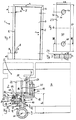
- Fig. 1
- eine Ansicht auf die Breitseite einer ein Türblatt und eine einen Links- oder Rechtsanschlag von Türblättern erlaubende Zarge umfassende Tür aus Holzwerkstoffen,
- Fig. 2
- eine Schnittansicht eines Seitenholms der Zarge mit einem Türscharnier und einer Verankerungsvorrichtung dafür sowie des angrenzenden Bereichs des Türblatts entlang der Linie II-II von Fig. 1 ,
- Fig. 3
- eine Unteransicht eines bei der Verankerungsvorrichtung nach Fig. 2 als Halteelement verwendeten Klemmblocks,
- Fig. 4
- eine geschnittene Seitenansicht des Klemmblocks entlang der Linie IV-IV von Fig. 3,
- Fig. 5
- eine Draufsicht auf den Klemmblock,
- Fig. 6
- eine Draufsicht auf ein in dem Klemmblock verschiebbar gehaltenes Gewindeteil, und
- Fig. 7
- eine Schnittansicht durch das Gewindeteil entlang der Linie VII-VII von Fig. 6.
- 1
- Tür
- 2
- Zarge
- 3
- Türblatt
- 4
- Querholm
- 5
- Seitenholm
- 6
- Seitenholm
- 7
- Zargenhauptfalz
- 8
- Türscharnier
- 9
- Schwenkzapfenlager (Türschwenklager)
- 10
- türblattseitige Bandlasche
- 11
- Aufnahme
- 12
- Türblattfalzvorsprung
- 13
- Türblatthauptfalz
- 14
- Verankerungsvorrichtung
- 15
- Bandlappen
- 16
- Bandtasche
- 17
- Vertiefung
- 18
- gefälzter Bereich
- 19
- zweites Halteelement
- 20
- freier Endbereich
- 21
- Bandtaschengehäuse
- 22
- taschenförmiger Hohlraum
- 23
- Gewindeteil (Verschiebeelement)
- 24
- Gewindeloch
- 25
- Madenschraube
- 26
- Gehäuse (Führung)
- 27
- Oberfläche des Zargenhauptfalzes
- 28
- Ende
- 29
- Ende
- 30
- Bodenplatte
- 31
- Deckplatte
- 32
- Abstandshalter
- 33
- Abstandshalter
- 34
- Innenseite der Bodenplatte
- 35
- Innenseite der Deckplatte
- 36
- Innenraum des Gehäuses
- 37
- Platte
- 38
- Längsseite des Gehäuses
- 39
- Längsseite des Gehäuses
- 40
- Hauptfläche des Gewindeteiles
- 41
- Hauptfläche des Gewindeteiles
- 42
- Befestigungsbohrung
- 43
- Befestigungsbohrung
- 44
- Gewindeloch
- 45
- Gewindeloch
- 46
- Durchgangsöffnung
- 47
- Durchgangsöffnungen
- A
- Schwenkachse
- a1
- Abstand der oberen Bandlage von dem Zargenhauptfalz
- a2
- Abstand der unteren Bandlage von der Stockunterkante
- a3
- Abstand Schwenkachse - Bandtasche
- a4
- Abstand Verschiebeelement - Bandlappen
- B
- Breitenrichtung
- D
- Dickenrichtung
- L
- Längenrichtung
- L1
- Länge des Gehäuses
- L2
- Länge des Innenraumes des Gehäuses
- L3
- Länge des Gewindeteiles
- L4
- Länge der Abstandshalter
- b1
- Breite des Gehäuses
- b3
- Breite des Gewindeteiles
- d1
- Dicke der Gehäuseplatten
- d2
- Dicke des Gewindeteils
- d3
- Dickenmaß
Claims (16)
- Verankerungsvorrichtung zum Verankern eines Türscharniers (8) insbesondere eines schweren Türblatts (3) an einer Zarge (2), mit einem an der Zarge (2) angeordneten ersten Halteelement zum Befestigen eines zargenseitigen Bandlappens (15) des Türscharniers (8) an der Zarge (2), wobei das erste Halteelement als Bandtasche (16) zum umgreifenden und insbesondere in Lage und Ausrichtung einstellbaren Aufnehmen und Befestigen des Bandlappens (15) ausgebildet ist,
gekennzeichnet durch ein zweites neben der Bandtasche (16) an der Zarge (2) vorgesehenes oder befestigbares Halteelement (19) zum Halten des Bandlappens (15) zusätzlich zu dessen Befestigung in der Bandtasche (16) in solch einer Weise, daß eine durch die Last des Türblattes (3) hervorgerufene Verwindung oder Verschwenkung des Bandlappens (15) vermieden wird. - Verankerungsvorrichtung nach Anspruch 1,
dadurch gekennzeichnet,
daß die Bandtasche (16) an einem inneren, gegenüber der Schwenkachse (A) des Türblattes (3) parallel zur Laibungsebene versetzten Bereich der Zarge (2), insbesondere in einem Falzbereich und mehr insbesondere bei doppelt gefalzter Tür (1) in einem Zargenhauptfalz (7), angeordnet ist und daß das zweite Halteelement (19) und der Bandlappen (15) zwischen der Handtasche (16) und der Schwenkachse (A) im Eingriff sind. - Verankerungsvorrichtung nach einem der Ansprüche 1 oder 2, dadurch gekennzeichnet,
daß das zweite Halteelement (19) und der Bandlappen (15) über wenigstens zwei vertikal beabstandete Angriffspunkte oder -bereiche (24/25/44/45) zur Übertragung von Drehmomenten oder dergleichen Verwindungs- oder Verschwenkungskräften in Eingriff miteinander sind. - Verankerungsvorrichtung nach einem der Ansprüche 1 bis 3, dadurch gekennzeichnet,
daß das zweite Halteelement (19) zum Anpassen an eine nach Einstellen und Ausrichten des Türblatts (3) vorliegende Bandlappenlage eine verschiebbar wählbare Halterung des Bandlappens (15) ermöglicht. - Verankerungsvorrichtung nach Anspruch 4,
dadurch gekennzeichnet,
daß das zweite Halteelement (19) ein in einer Führung (26) an der Zarge (2) parallel zur Laibungs- und/oder Bandlappenebene verschiebbar gehaltenes Verschiebeelement (23) umfaßt, welches mit dem Bandlappen (15) verbunden oder verbindbar ist. - Verankerungsvorrichtung nach Anspruch 5,
dadurch gekennzeichnet,
daß das Verschiebeelement (23) eine von der Führung (26) randseitig umgriffene Platte (37) ist, die insbesondere zum Aufnehmen eines die Platte (37) mit dem Bandlappen (15) verbindenden Befestigers (25) ausgebildet ist. - Verankerungsvorrichtung nach einem der Ansprüche 5 oder 6, dadurch gekennzeichnet,
daß die Führung durch ein an der Zarge (2) insbesondere in versenkter Position (17, 18) befestigtes Gehäuse (26) oder eine an der Zarge (2) vorgesehene zweite Bandtasche gebildet ist, in welchem bzw. welcher das Verschiebeelement (23) derart aufgenommen ist, daß es zusammen mit dem Bandlappen (15) parallel zur Laibungs- und/oder Bandlappenebene sowohl in horizontaler als auch in vertikaler Richtung verschieblich ist, in Richtung senkrecht zur Laibungs- oder Bandlappenebene aber festgehalten wird, und welches bzw. welche mit Ausnehmungen (46) versehen ist, durch die eine zur Übertragung von auf den Bandlappen (15) einwirkenden Drehmomenten oder dergleichen Verwindungskräften geeignete, insbesondere in Abstand und relativer Lage zwischen Bandlappen (15) und Verschiebeelement (23) an die Bandlappenlage anpaßbare Verbindung zwischen dem Verschiebeelement (23) und dem Bandlappen (15) erfolgen kann. - Verankerungsvorrichtung nach Anspruch 7,
dadurch gekennzeichnet,
daß das Gehäuse (26) oder die zweite Bandtasche eine Bodenplatte (30), eine Deckplatte (31) und zwei Abstandshalter (32, 33) aufweisen und an der Zarge (2) mittels Befestigungsschrauben oder dergleichen gehalten sind. - Verankerungsvorrichtung nach einem der Ansprüche 5 bis 8, dadurch gekennzeichnet,
daß die Führung (26) eine insbesondere bei Angreifen von Drehmomenten auf das Verschiebeelement (23) wirksame Klemmeinrichtung zum Verklemmen des Verschiebeelements (23) aufweist. - Verankerungsvorrichtung nach Anspruch 8 und 9,
dadurch gekennzeichnet,
daß das Gehäuse (26) derart ausgeführt ist, daß das Verschiebeelement (23) durch Festziehen der Befestigungsschrauben zwischen der Bodenplatte (30) und der Deckplatte (31) nach Ausrichten des Türblatts (3) verklemmbar ist. - Verankerungsvorrichtung nach einem der Ansprüche 5 bis 9, dadurch gekennzeichnet,
daß das Verschiebeelement (23) in der Führung (26) mit Spiel gehalten ist, das so gering ist, daß das Verschiebeelement (23) parallel zur Laibungsebene oder Bandlappenebene verschiebbar ist, bei Angreifen eines Drehmoments aber in der Führung (26) verkantet, vorzugsweise dergestalt, daß es sich einer Verschiebung verklemmend widersetzt. - Verankerungsvorrichtung nach Anspruch 11 und Anspruch 8, dadurch gekennzeichnet,
daß das Spiel durch die Abstandshalter (32, 33) gewährleistet wird, die einen das Spiel zulassenden Abstand (a5) zwischen der Bodenplatte (30) und der Deckplatte (31) auch bei festgezogenen Befestigungsschrauben aufrechterhalten. - Verankerungsvorrichtung nach einem der Ansprüche 5 bis 12, dadurch gekennzeichnet,
daß das Verschiebeelement (23) mit einem Gewindeloch, bevorzugt aber zum Bilden der wenigstens zwei Angriffspunkte mit wenigstens zwei Gewindelöchern (44, 45) versehen ist, zum Bieten je eines Angriffs für eine den Bandlappen (15) mit dem Verschiebeelement (23) verbindende Schraube, insbesondere einer Madenschraube (25). - Verankerungsvorrichtung nach Anspruch 12,
gekennzeichnet durch eine insbesondere eine Verklebung umfassende Sicherungseinrichtung, die ein Lösen oder Herausdrehen der Schraube (25) bzw. der Schrauben (25) aus dem Gewindeloch oder den Gewindelöchern (44, 45) verhindert. - Tür, insbesondere auf der Basis von Holzwerkstoffen aufgebaute und vorzugsweise zum Rauch- und/oder Feuerschutz ausgelegte Tür gekennzeichnet durch wenigstens eine Verankerungsvorrichtung (14) nach einem der Ansprüche 1 bis 14.
- Tür nach Anspruch 15,
dadurch gekennzeichnet,
daß beide Seitenholme (5, 6) der Zarge (2) für wahlweisen Links- oder Rechtsanschlag eines Türblattes (3) vorbereitet sind und insbesondere die beiden Halteelemente (16, 19) aufweisen.
Applications Claiming Priority (2)
| Application Number | Priority Date | Filing Date | Title |
|---|---|---|---|
| DE29814666U DE29814666U1 (de) | 1998-08-14 | 1998-08-14 | Verankerungsvorrichtung zum Verankern eines Türscharniers in einer Zarge und mit einer solchen Verankerungsvorrichtung versehene Tür |
| DE29814666U | 1998-08-14 |
Publications (3)
| Publication Number | Publication Date |
|---|---|
| EP0980949A2 true EP0980949A2 (de) | 2000-02-23 |
| EP0980949A3 EP0980949A3 (de) | 2000-03-01 |
| EP0980949B1 EP0980949B1 (de) | 2002-07-10 |
Family
ID=8061338
Family Applications (1)
| Application Number | Title | Priority Date | Filing Date |
|---|---|---|---|
| EP99115624A Expired - Lifetime EP0980949B1 (de) | 1998-08-14 | 1999-08-07 | Tür mit einer Verankerungsvorrichtung zum Verankern eines Türscharniers in einer Zarge |
Country Status (3)
| Country | Link |
|---|---|
| EP (1) | EP0980949B1 (de) |
| AT (1) | ATE220442T1 (de) |
| DE (2) | DE29814666U1 (de) |
Cited By (1)
| Publication number | Priority date | Publication date | Assignee | Title |
|---|---|---|---|---|
| EP1215356A3 (de) * | 2000-12-18 | 2006-04-05 | Dr. Hahn GmbH & Co. KG | Bandanordnung für Türen, Fenster und dergleichen |
Families Citing this family (1)
| Publication number | Priority date | Publication date | Assignee | Title |
|---|---|---|---|---|
| DE10149810B4 (de) * | 2001-10-09 | 2007-01-04 | Albert Nehlig | Anordnung eines gefälzten Türblattes an einer Zarge |
Family Cites Families (3)
| Publication number | Priority date | Publication date | Assignee | Title |
|---|---|---|---|---|
| DE3905308A1 (de) * | 1989-02-21 | 1990-08-23 | Riexinger Tuerenwerk | Tuer, bestehend aus zwei tuerblatteilen, insbesondere feuerschutztuer |
| DE4408346A1 (de) * | 1993-11-26 | 1995-06-01 | Riexinger Tuerenwerk | Türflügel für ein Gebäude o. dgl. und Verfahren zum Herstellen eines Türflügels |
| DE29803644U1 (de) * | 1998-03-03 | 1998-06-10 | Hans Weber Metallwarenfabrik GmbH, 90443 Nürnberg | Verstellbare Unterkonstruktion für Holztüren |
-
1998
- 1998-08-14 DE DE29814666U patent/DE29814666U1/de not_active Expired - Lifetime
-
1999
- 1999-08-07 DE DE59901987T patent/DE59901987D1/de not_active Expired - Lifetime
- 1999-08-07 AT AT99115624T patent/ATE220442T1/de not_active IP Right Cessation
- 1999-08-07 EP EP99115624A patent/EP0980949B1/de not_active Expired - Lifetime
Cited By (1)
| Publication number | Priority date | Publication date | Assignee | Title |
|---|---|---|---|---|
| EP1215356A3 (de) * | 2000-12-18 | 2006-04-05 | Dr. Hahn GmbH & Co. KG | Bandanordnung für Türen, Fenster und dergleichen |
Also Published As
| Publication number | Publication date |
|---|---|
| DE29814666U1 (de) | 1999-12-16 |
| ATE220442T1 (de) | 2002-07-15 |
| EP0980949B1 (de) | 2002-07-10 |
| EP0980949A3 (de) | 2000-03-01 |
| DE59901987D1 (de) | 2002-08-14 |
Similar Documents
| Publication | Publication Date | Title |
|---|---|---|
| DE102007019938B3 (de) | Türband | |
| DE4219681C2 (de) | Einstellbares Abhebescharnier | |
| EP1893836B1 (de) | Möbelscharnier | |
| DE102010004772B3 (de) | Türband für Aluminiumtüren | |
| DE102011006023B3 (de) | Verstellbares Scharnierband | |
| EP2345786B1 (de) | Türband für Aluminiumtüren | |
| EP0837206B1 (de) | Türscharnier zur schwenkbaren Lagerung eines Türflügels an einem Türrahmen | |
| EP0980949B1 (de) | Tür mit einer Verankerungsvorrichtung zum Verankern eines Türscharniers in einer Zarge | |
| DE19944549B4 (de) | Verschwindscharnier | |
| DE202008016071U1 (de) | Band zur scharniergelenkigen Verbindung eines Flügels an einem Rahmen | |
| EP1936083B1 (de) | Stützvorrichtung für ein Scharnier einer Schließeinheit | |
| EP0874123B1 (de) | Beschlag zur Lagerung des Drehflügels eines Fensters oder einer Tür | |
| DE102020121334B3 (de) | Türband zur schwenkbaren Lagerung eines Türflügels in einem Rahmen | |
| EP1301676B1 (de) | Fenster oder tür mit entlastungseinrichtung | |
| EP3029227B2 (de) | Beschlag mit einstellbarem Einspannbereich | |
| WO2022194950A1 (de) | Band fuer eine tuer oder ein fenster | |
| EP1915498B1 (de) | Profilbandsystem | |
| EP1319786A1 (de) | Scharnier | |
| EP0943770B1 (de) | Tür- oder Fensterband | |
| DE102007025857A1 (de) | Gelenkband für Türen oder Fenster | |
| AT411478B (de) | Türband | |
| EP3516143B1 (de) | Beschlaganordnung | |
| DE202024000575U1 (de) | Bandachse, Band und Industriemöbel | |
| DE4447468C2 (de) | Beschlag zur schwenkbaren Befestigung des Flügels einer Tür oder eines Fensters an einem Rahmen | |
| DE3822000C2 (de) |
Legal Events
| Date | Code | Title | Description |
|---|---|---|---|
| PUAI | Public reference made under article 153(3) epc to a published international application that has entered the european phase |
Free format text: ORIGINAL CODE: 0009012 |
|
| PUAL | Search report despatched |
Free format text: ORIGINAL CODE: 0009013 |
|
| AK | Designated contracting states |
Kind code of ref document: A2 Designated state(s): AT BE CH CY DE DK ES FI FR GB GR IE IT LI LU MC NL PT SE |
|
| AX | Request for extension of the european patent |
Free format text: AL;LT;LV;MK;RO;SI |
|
| AK | Designated contracting states |
Kind code of ref document: A3 Designated state(s): AT BE CH CY DE DK ES FI FR GB GR IE IT LI LU MC NL PT SE |
|
| AX | Request for extension of the european patent |
Free format text: AL;LT;LV;MK;RO;SI |
|
| RIC1 | Information provided on ipc code assigned before grant |
Free format text: 7E 05D 5/06 A, 7E 05D 5/02 B, 7E 05D 7/04 B |
|
| 17P | Request for examination filed |
Effective date: 20000811 |
|
| AKX | Designation fees paid |
Free format text: AT BE CH CY DE DK ES FI FR GB GR IE IT LI LU MC NL PT SE |
|
| 17Q | First examination report despatched |
Effective date: 20001213 |
|
| RTI1 | Title (correction) |
Free format text: DOOR WITH AN ANCHORING DEVICE FOR ANCHORING A DOOR HINGE IN A FRAME |
|
| GRAG | Despatch of communication of intention to grant |
Free format text: ORIGINAL CODE: EPIDOS AGRA |
|
| GRAG | Despatch of communication of intention to grant |
Free format text: ORIGINAL CODE: EPIDOS AGRA |
|
| GRAH | Despatch of communication of intention to grant a patent |
Free format text: ORIGINAL CODE: EPIDOS IGRA |
|
| GRAH | Despatch of communication of intention to grant a patent |
Free format text: ORIGINAL CODE: EPIDOS IGRA |
|
| GRAA | (expected) grant |
Free format text: ORIGINAL CODE: 0009210 |
|
| AK | Designated contracting states |
Kind code of ref document: B1 Designated state(s): AT BE CH CY DE DK ES FI FR GB GR IE IT LI LU MC NL PT SE |
|
| PG25 | Lapsed in a contracting state [announced via postgrant information from national office to epo] |
Ref country code: NL Free format text: LAPSE BECAUSE OF FAILURE TO SUBMIT A TRANSLATION OF THE DESCRIPTION OR TO PAY THE FEE WITHIN THE PRESCRIBED TIME-LIMIT Effective date: 20020710 Ref country code: IT Free format text: LAPSE BECAUSE OF FAILURE TO SUBMIT A TRANSLATION OF THE DESCRIPTION OR TO PAY THE FEE WITHIN THE PRE;WARNING: LAPSES OF ITALIAN PATENTS WITH EFFECTIVE DATE BEFORE 2007 MAY HAVE OCCURRED AT ANY TIME BEFORE 2007. THE CORRECT EFFECTIVE DATE MAY BE DIFFERENT FROM THE ONE RECORDED.SCRIBED TIME-LIMIT Effective date: 20020710 Ref country code: IE Free format text: LAPSE BECAUSE OF FAILURE TO SUBMIT A TRANSLATION OF THE DESCRIPTION OR TO PAY THE FEE WITHIN THE PRESCRIBED TIME-LIMIT Effective date: 20020710 Ref country code: GR Free format text: LAPSE BECAUSE OF FAILURE TO SUBMIT A TRANSLATION OF THE DESCRIPTION OR TO PAY THE FEE WITHIN THE PRESCRIBED TIME-LIMIT Effective date: 20020710 Ref country code: GB Free format text: LAPSE BECAUSE OF FAILURE TO SUBMIT A TRANSLATION OF THE DESCRIPTION OR TO PAY THE FEE WITHIN THE PRESCRIBED TIME-LIMIT Effective date: 20020710 Ref country code: FR Free format text: LAPSE BECAUSE OF FAILURE TO SUBMIT A TRANSLATION OF THE DESCRIPTION OR TO PAY THE FEE WITHIN THE PRESCRIBED TIME-LIMIT Effective date: 20020710 Ref country code: FI Free format text: LAPSE BECAUSE OF FAILURE TO SUBMIT A TRANSLATION OF THE DESCRIPTION OR TO PAY THE FEE WITHIN THE PRESCRIBED TIME-LIMIT Effective date: 20020710 |
|
| REF | Corresponds to: |
Ref document number: 220442 Country of ref document: AT Date of ref document: 20020715 Kind code of ref document: T |
|
| REG | Reference to a national code |
Ref country code: GB Ref legal event code: FG4D Free format text: NOT ENGLISH |
|
| REG | Reference to a national code |
Ref country code: CH Ref legal event code: EP |
|
| REG | Reference to a national code |
Ref country code: CH Ref legal event code: NV Representative=s name: PATENTANWALTSBUERO EDER AG |
|
| PG25 | Lapsed in a contracting state [announced via postgrant information from national office to epo] |
Ref country code: LU Free format text: LAPSE BECAUSE OF NON-PAYMENT OF DUE FEES Effective date: 20020807 |
|
| REG | Reference to a national code |
Ref country code: IE Ref legal event code: FG4D Free format text: GERMAN |
|
| REF | Corresponds to: |
Ref document number: 59901987 Country of ref document: DE Date of ref document: 20020814 |
|
| PG25 | Lapsed in a contracting state [announced via postgrant information from national office to epo] |
Ref country code: CY Free format text: LAPSE BECAUSE OF FAILURE TO SUBMIT A TRANSLATION OF THE DESCRIPTION OR TO PAY THE FEE WITHIN THE PRESCRIBED TIME-LIMIT Effective date: 20020831 Ref country code: BE Free format text: LAPSE BECAUSE OF NON-PAYMENT OF DUE FEES Effective date: 20020831 |
|
| PG25 | Lapsed in a contracting state [announced via postgrant information from national office to epo] |
Ref country code: SE Free format text: LAPSE BECAUSE OF FAILURE TO SUBMIT A TRANSLATION OF THE DESCRIPTION OR TO PAY THE FEE WITHIN THE PRESCRIBED TIME-LIMIT Effective date: 20021010 Ref country code: PT Free format text: LAPSE BECAUSE OF FAILURE TO SUBMIT A TRANSLATION OF THE DESCRIPTION OR TO PAY THE FEE WITHIN THE PRESCRIBED TIME-LIMIT Effective date: 20021010 Ref country code: DK Free format text: LAPSE BECAUSE OF FAILURE TO SUBMIT A TRANSLATION OF THE DESCRIPTION OR TO PAY THE FEE WITHIN THE PRESCRIBED TIME-LIMIT Effective date: 20021010 |
|
| NLV1 | Nl: lapsed or annulled due to failure to fulfill the requirements of art. 29p and 29m of the patents act | ||
| GBV | Gb: ep patent (uk) treated as always having been void in accordance with gb section 77(7)/1977 [no translation filed] |
Effective date: 20020710 |
|
| PG25 | Lapsed in a contracting state [announced via postgrant information from national office to epo] |
Ref country code: ES Free format text: LAPSE BECAUSE OF FAILURE TO SUBMIT A TRANSLATION OF THE DESCRIPTION OR TO PAY THE FEE WITHIN THE PRESCRIBED TIME-LIMIT Effective date: 20030130 |
|
| EN | Fr: translation not filed | ||
| BERE | Be: lapsed |
Owner name: *SCHORGHUBER SPEZIALTUREN G.M.B.H. & CO. BETRIEBS- Effective date: 20020831 |
|
| PG25 | Lapsed in a contracting state [announced via postgrant information from national office to epo] |
Ref country code: MC Free format text: LAPSE BECAUSE OF NON-PAYMENT OF DUE FEES Effective date: 20030301 |
|
| REG | Reference to a national code |
Ref country code: IE Ref legal event code: FD4D Ref document number: 0980949E Country of ref document: IE |
|
| PLBE | No opposition filed within time limit |
Free format text: ORIGINAL CODE: 0009261 |
|
| STAA | Information on the status of an ep patent application or granted ep patent |
Free format text: STATUS: NO OPPOSITION FILED WITHIN TIME LIMIT |
|
| 26N | No opposition filed |
Effective date: 20030411 |
|
| PGFP | Annual fee paid to national office [announced via postgrant information from national office to epo] |
Ref country code: CH Payment date: 20050727 Year of fee payment: 7 |
|
| PGFP | Annual fee paid to national office [announced via postgrant information from national office to epo] |
Ref country code: AT Payment date: 20050812 Year of fee payment: 7 |
|
| PG25 | Lapsed in a contracting state [announced via postgrant information from national office to epo] |
Ref country code: AT Free format text: LAPSE BECAUSE OF NON-PAYMENT OF DUE FEES Effective date: 20060807 |
|
| PG25 | Lapsed in a contracting state [announced via postgrant information from national office to epo] |
Ref country code: LI Free format text: LAPSE BECAUSE OF NON-PAYMENT OF DUE FEES Effective date: 20060831 Ref country code: CH Free format text: LAPSE BECAUSE OF NON-PAYMENT OF DUE FEES Effective date: 20060831 |
|
| REG | Reference to a national code |
Ref country code: CH Ref legal event code: PL |
|
| PGFP | Annual fee paid to national office [announced via postgrant information from national office to epo] |
Ref country code: DE Payment date: 20091027 Year of fee payment: 11 |
|
| REG | Reference to a national code |
Ref country code: DE Ref legal event code: R119 Ref document number: 59901987 Country of ref document: DE Effective date: 20110301 |
|
| PG25 | Lapsed in a contracting state [announced via postgrant information from national office to epo] |
Ref country code: DE Free format text: LAPSE BECAUSE OF NON-PAYMENT OF DUE FEES Effective date: 20110301 |