EP0980950A2 - Charniére - Google Patents
Charniére Download PDFInfo
- Publication number
- EP0980950A2 EP0980950A2 EP99115704A EP99115704A EP0980950A2 EP 0980950 A2 EP0980950 A2 EP 0980950A2 EP 99115704 A EP99115704 A EP 99115704A EP 99115704 A EP99115704 A EP 99115704A EP 0980950 A2 EP0980950 A2 EP 0980950A2
- Authority
- EP
- European Patent Office
- Prior art keywords
- hinge
- spindles
- base plate
- hinge arm
- door
- Prior art date
- Legal status (The legal status is an assumption and is not a legal conclusion. Google has not performed a legal analysis and makes no representation as to the accuracy of the status listed.)
- Withdrawn
Links
- 210000001520 comb Anatomy 0.000 description 2
- 208000018459 dissociative disease Diseases 0.000 description 1
- 230000001771 impaired effect Effects 0.000 description 1
- 230000001360 synchronised effect Effects 0.000 description 1
Images


Classifications
-
- E—FIXED CONSTRUCTIONS
- E05—LOCKS; KEYS; WINDOW OR DOOR FITTINGS; SAFES
- E05D—HINGES OR SUSPENSION DEVICES FOR DOORS, WINDOWS OR WINGS
- E05D7/00—Hinges or pivots of special construction
- E05D7/04—Hinges adjustable relative to the wing or the frame
- E05D7/0407—Hinges adjustable relative to the wing or the frame the hinges having two or more pins and being specially adapted for cabinets or furniture
-
- E—FIXED CONSTRUCTIONS
- E05—LOCKS; KEYS; WINDOW OR DOOR FITTINGS; SAFES
- E05Y—INDEXING SCHEME ASSOCIATED WITH SUBCLASSES E05D AND E05F, RELATING TO CONSTRUCTION ELEMENTS, ELECTRIC CONTROL, POWER SUPPLY, POWER SIGNAL OR TRANSMISSION, USER INTERFACES, MOUNTING OR COUPLING, DETAILS, ACCESSORIES, AUXILIARY OPERATIONS NOT OTHERWISE PROVIDED FOR, APPLICATION THEREOF
- E05Y2900/00—Application of doors, windows, wings or fittings thereof
- E05Y2900/20—Application of doors, windows, wings or fittings thereof for furniture, e.g. cabinets
Definitions
- the invention relates to a hinge with an adjustment device for one on one Base plate mounted hinge arm, which by means of an articulated lever or the like.
- a door-side Stop part for example a hinge cup is connected, the base plate in assembled state with a mounting surface on a furniture side wall and by means of the adjustment, the position of the hinge arm relative to the base plate to the side Adjustment of a door is changeable.
- the hinge arm is clamped on the Base plate or an intermediate piece attached. So that an adjustment of the hinge arm is possible in the depth of the furniture, this clamping screw protrudes through an elongated hole in the Hinge arm. The possibility of adjusting the hinge arm in the depth of the furniture is determined by the length of this elongated hole.
- an adjustment option for the position of the hinge arm is generally relative to the base plate in the direction of the furniture joint, i.e. perpendicular to the side wall of the furniture intended.
- This adjustment is achieved by a so-called joint adjustment screw which is stored in a nut thread of the hinge arm and with its head in one Recess of the base plate or the intermediate piece is held.
- the hinge arms are generally not directly on the base plate stored, but indirectly via an intermediate piece, which is between the hinge arm and the base plate.
- a hinge examples of such a hinge are shown in WO 86/02402.
- This kind of Hinge allows when assembling the furniture, i.e. H. when hanging the furniture door the hinge arm together with the attached intermediate piece quickly and to be anchored without tools to a base plate that is attached to a side wall of the furniture. Nevertheless, if necessary, the position of the hinge arm can then be relative to Base plate (and to the intermediate piece) after loosening a clamping screw by the joint adjustment screw respectively.
- a hinge is known from EP 0 168 731 B, in which a guide for the hinge arm is provided, which causes them in a side adjustment of the position of the hinge arm this is also placed in the depth of the furniture on the base plate.
- the object of the invention is to provide a hinge of the type mentioned improve that a more precise positioning of the hinge arm with a side adjustment the door is achieved.
- the adjusting device at least comprises two spindles offset in the longitudinal direction of the hinge arm, which rotate with one another are connected.
- An embodiment of the invention provides that the spindles are provided with a ring gear are, wherein the sprockets are connected either by a toothed belt, the combs with the ring gears or that an intermediate gear is provided, which with the Sprockets of two spindles are engaged.
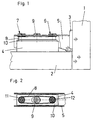
- the hinge according to the invention has a hinge arm 5, which has an intermediate piece 10, 24 can be mounted on a base plate 4.
- the base plate 4 is by means of screws or the like. attached to a furniture side wall 2 and lies with its mounting surface on the furniture side wall 2 on.
- a further intermediate piece could also be used be provided, for example, as shown in WO86 / 02402, by means of a snap mechanism can be attached to a base plate.
- the hinge arm 5 is over Articulated lever, not shown, connected to a hinge cup 3, which can be inserted into a door 1 is.
- the intermediate piece 10 is by means of a depth adjustment screw 9, which protrudes through a longitudinal slot 25 of the intermediate piece 10 and in a mother thread of the base plate 4 is clamped to the base plate 4.
- a depth adjustment screw 9 which protrudes through a longitudinal slot 25 of the intermediate piece 10 and in a mother thread of the base plate 4 is clamped to the base plate 4.
- the intermediate piece 10 with the hinge arm 5 can be moved in the direction of the depth of the furniture on the base plate 4.
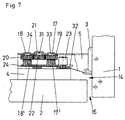
- the lateral adjustment of the hinge arm 5, d. H. the adjustment of the joint of the door 1 is achieved by turning the spindles 6, 7, 17, 18.
- the spindles 6, 7, 17, 18 also support their threaded sections 6 ', 7', 17 ', 18' in nut threads in the intermediate pieces 10 and 24th
- the spindles 6, 7 are adjacent to their Heads 26, 27, which rest against the hinge arm 6, with tapered sections 28, 29 Mistake.
- Sprockets 11, 12 are supported on these tapered sections 11, 12 runs a toothed belt 8.
- the toothed belt 8 and the ring gears 11, 12 the synchronous rotation of the spindles 6, 7 is ensured, d. that is, one of the spindles 6, 7 rotated, for example by means of a screwdriver which engages the head 26, 27, the second spindle 6, 7 is rotated to the same extent via the toothed belt 8, so that the hinge arm 5 is moved exactly perpendicular to the side wall 2 of the furniture.
- the spindles 6, 7 protrude through longitudinal slots 30 in the base plate 4.
- the depth adjustment screw 9 is located between the two spindles 6, 7 and is from Surround toothed belt 8.
- the depth adjustment of the hinge arm 5 is not the spindles 6, 7 and the toothed belt 8 impaired and the lateral adjustment of the Hinge arm 5 is completely independent of the depth adjustment screw 9.
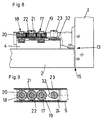
- 4, 5 are the limits of the adjustment ranges for the door 1 in the direction of Fugue, d. H. shown in the lateral direction and in the depth of the furniture. 3 shows the Arrow 13 the smallest distance between the hinge arm 5 and the furniture side wall 2, d. H. the position of the door 1 with minimal or no gap between the joints.
- the reference numeral 15 shows the smallest distance between the door 1 and the front edge the furniture side wall 2, while in FIG. 6 the reference number 16 is the largest possible Distance between the door 1 and the furniture side wall 2 shows.
- the spindles 17, 18 are surrounding Sprockets 19, 20 by an intermediate gear 22, which with the two sprockets 18, 19th combs, coupled.
- the intermediate gear 22 is through a drive shaft 21 on the hinge arm 5 stored. If the intermediate gear 22, for example by a screwdriver, who engages the tool holder 31 of the drive shaft 21, rotated, the Spindles 17, 18 are also rotated to the same extent, as a result of which the hinge arm 5 is either moved towards the furniture side wall 2 or away from it.
- the depth adjustment screw 23 is between the spindle 17 and the end of the base plate 4 or the intermediate piece 24 near the door.
- the Depth adjustment screw 23 is supported in a nut thread of the base plate 4 and protrudes through a slot 32 of the intermediate piece 24 which is open towards the front.
- reference numerals 13, 14, 15, 16 are again the different ones Clearances between the door 1 and the furniture side wall 2 and the hinge arm 5 and the furniture side wall 2 shown.
- the spindles 17, 18 in turn have tapered sections, in the area of which the sprockets 19, 20 are supported and supported with heads 33, 34 on the outside of the hinge arm 5.
Landscapes
- Engineering & Computer Science (AREA)
- Mechanical Engineering (AREA)
- Hinges (AREA)
Applications Claiming Priority (2)
| Application Number | Priority Date | Filing Date | Title |
|---|---|---|---|
| AT0139998A AT406497B (de) | 1998-08-17 | 1998-08-17 | Scharnier |
| AT139998 | 1998-08-17 |
Publications (2)
| Publication Number | Publication Date |
|---|---|
| EP0980950A2 true EP0980950A2 (fr) | 2000-02-23 |
| EP0980950A3 EP0980950A3 (fr) | 2000-05-03 |
Family
ID=3513047
Family Applications (1)
| Application Number | Title | Priority Date | Filing Date |
|---|---|---|---|
| EP99115704A Withdrawn EP0980950A3 (fr) | 1998-08-17 | 1999-08-10 | Charniére |
Country Status (4)
| Country | Link |
|---|---|
| US (1) | US6205617B1 (fr) |
| EP (1) | EP0980950A3 (fr) |
| AT (1) | AT406497B (fr) |
| BR (1) | BR9903725A (fr) |
Cited By (1)
| Publication number | Priority date | Publication date | Assignee | Title |
|---|---|---|---|---|
| WO2025144132A1 (fr) * | 2023-12-28 | 2025-07-03 | Samet Kalip Ve Madeni̇ Eşya San Ve Ti̇c. A.Ş | Agencement de montage pour une charnière |
Families Citing this family (11)
| Publication number | Priority date | Publication date | Assignee | Title |
|---|---|---|---|---|
| AT409288B (de) * | 2000-02-28 | 2002-07-25 | Blum Gmbh Julius | Möbelscharnier |
| DE20302524U1 (de) * | 2003-02-17 | 2004-06-24 | Arturo Salice S.P.A., Novedrate | Vorrichtung zur Dämpfung der Bewegung beweglicher Möbelteile in deren Schließbereich |
| CN101354057B (zh) * | 2007-07-26 | 2012-05-16 | 鸿富锦精密工业(深圳)有限公司 | 螺丝 |
| ITVI20080070A1 (it) * | 2008-03-21 | 2009-09-22 | Ares Engineering Srl | Mezzi di articolazione |
| US8186781B2 (en) * | 2009-05-07 | 2012-05-29 | Whirlpool Corporation | Articulated hinges using non-circular gears |
| US8267492B2 (en) * | 2009-05-07 | 2012-09-18 | Whirlpool Corporation | Method of routing utilities through an articulated hinge |
| US10087971B1 (en) * | 2015-10-08 | 2018-10-02 | Joshua T. Bergan | Planetary stapler for electrical wiring and the like |
| DE102015226543A1 (de) * | 2015-12-22 | 2017-06-22 | Rolls-Royce Deutschland Ltd & Co Kg | Triebwerksverkleidung |
| AT519666B1 (de) * | 2017-11-24 | 2018-09-15 | Blum Gmbh Julius | Möbelbeschlag |
| US10822852B1 (en) * | 2019-07-19 | 2020-11-03 | Haier Us Appliance Solutions, Inc. | Linear hinge assembly for an appliance |
| DE102023120420A1 (de) * | 2023-08-01 | 2025-02-06 | Grass Gmbh | Vorrichtung für eine schwenkbare Verbindung von einem Möbelkorpus und einem beweglichen Möbelteil |
Citations (2)
| Publication number | Priority date | Publication date | Assignee | Title |
|---|---|---|---|---|
| WO1986002404A1 (fr) | 1984-10-18 | 1986-04-24 | Gislaved Ab | Dispositif de fragmentation de pierres, de rochers, de beton et d'autres materiaux similaires |
| EP0168731B1 (fr) | 1984-07-17 | 1989-05-03 | Arturo Salice S.p.A. | Charnière pour meuble |
Family Cites Families (9)
| Publication number | Priority date | Publication date | Assignee | Title |
|---|---|---|---|---|
| AT364275B (de) * | 1974-05-27 | 1981-10-12 | Grass Alfred Metallwaren | Hoeheneinstellbares moebelscharnier |
| AT365284B (de) * | 1974-11-14 | 1981-12-28 | Grass Alfred Metallwaren | Moebelscharnier mit einer seiten- und hoehenverstellungseinrichtung |
| EP0097766B1 (fr) * | 1982-06-26 | 1985-11-21 | Karl Lautenschläger KG Möbelbeschlagfabrik | Charnière pour meuble |
| DE3577222D1 (de) * | 1984-10-19 | 1990-05-23 | Blum Gmbh Julius | Scharnier. |
| US5056190A (en) * | 1984-10-19 | 1991-10-15 | Julius Blum Gesellschaft M.B.H. | Hinge with hinge arm releasably connected to mounting plate |
| DE3624237A1 (de) * | 1986-03-06 | 1987-09-10 | Grass Alfred Metallwaren | Scharnierband mit leicht loesbarer befestigung des moebelseitigen abdeckbuegels am moebelteil |
| US5379487A (en) * | 1993-07-19 | 1995-01-10 | Amerock Corporation | Hinge with adjustable hinge arm |
| DE4341422C2 (de) * | 1993-12-04 | 1995-09-07 | Keusch Gmbh | Topfscharnier |
| US5934853A (en) * | 1997-10-24 | 1999-08-10 | Junkers; John K. | Nut and device for tightening provided with the same |
-
1998
- 1998-08-17 AT AT0139998A patent/AT406497B/de not_active IP Right Cessation
-
1999
- 1999-08-10 EP EP99115704A patent/EP0980950A3/fr not_active Withdrawn
- 1999-08-11 US US09/372,097 patent/US6205617B1/en not_active Expired - Fee Related
- 1999-08-17 BR BR9903725-4A patent/BR9903725A/pt not_active Application Discontinuation
Patent Citations (2)
| Publication number | Priority date | Publication date | Assignee | Title |
|---|---|---|---|---|
| EP0168731B1 (fr) | 1984-07-17 | 1989-05-03 | Arturo Salice S.p.A. | Charnière pour meuble |
| WO1986002404A1 (fr) | 1984-10-18 | 1986-04-24 | Gislaved Ab | Dispositif de fragmentation de pierres, de rochers, de beton et d'autres materiaux similaires |
Cited By (1)
| Publication number | Priority date | Publication date | Assignee | Title |
|---|---|---|---|---|
| WO2025144132A1 (fr) * | 2023-12-28 | 2025-07-03 | Samet Kalip Ve Madeni̇ Eşya San Ve Ti̇c. A.Ş | Agencement de montage pour une charnière |
Also Published As
| Publication number | Publication date |
|---|---|
| US6205617B1 (en) | 2001-03-27 |
| BR9903725A (pt) | 2000-08-29 |
| AT406497B (de) | 2000-05-25 |
| ATA139998A (de) | 1999-10-15 |
| EP0980950A3 (fr) | 2000-05-03 |
Similar Documents
| Publication | Publication Date | Title |
|---|---|---|
| EP1140400B1 (fr) | Outil a enlevement de copeaux pour usinage a vitesse elevee | |
| AT1214U1 (de) | Scharnier | |
| EP0982455A2 (fr) | Charnière de meuble | |
| EP2297418B1 (fr) | Charniere | |
| AT406497B (de) | Scharnier | |
| EP0285229B2 (fr) | Charnière réglable, en particulier pour portes | |
| EP1108845B1 (fr) | Mécanisme de roulement pour porte coulissante | |
| DE19742511C2 (de) | Schubstangenverschluß für eine an einem Schaltschrank-Korpus angelenkte Schranktüre | |
| EP1091067A1 (fr) | Charnière pour portes ou fenêtres | |
| EP0410104B1 (fr) | Outil d'usinage par enlèvement de copeaux | |
| EP0841447A1 (fr) | Gâche automatique avec une pièce de blocage réglable et pivotante | |
| DE102006005572B4 (de) | Stanzvorrichtung | |
| DE19963818A1 (de) | Zange mit verstellbarer Maulweite für Einhandbedienung | |
| EP0212484B2 (fr) | Ferme-porte | |
| DE29914473U1 (de) | Scharnier | |
| DE102004035263B3 (de) | Werkzeughalter einer Werkzeugmaschine | |
| EP0729540B1 (fr) | Paumelle de porte ou de fenetre | |
| DE202007004957U1 (de) | Stanzvorrichtung | |
| DE3940926C2 (de) | Demontierbares Türscharnier für Kraftfahrzeugtüren | |
| EP0340455B2 (fr) | Pivot pour la connexion de deux battants d'une fenêtre, d'une porte ou similaire | |
| EP0249184B1 (fr) | Dispositif à fileter | |
| EP0674079B1 (fr) | Palier d'angle inférieur pour un ouvrant oscillo-battant d'une fenêtre, d'une porte ou similaire | |
| DE19842769A1 (de) | Türband zur schwenkbaren Anbringung eines Türflügels an einem Türrahmen | |
| EP0987393B1 (fr) | Paumelle pour le montage pivotant d'un vantail de porte sur un cadre | |
| AT386861B (de) | Tuerscharnier mit einstellanordnung zur seitenund hoeheneinstellung |
Legal Events
| Date | Code | Title | Description |
|---|---|---|---|
| PUAI | Public reference made under article 153(3) epc to a published international application that has entered the european phase |
Free format text: ORIGINAL CODE: 0009012 |
|
| AK | Designated contracting states |
Kind code of ref document: A2 Designated state(s): AT BE CH CY DE DK ES FI FR GB GR IE IT LI LU MC NL PT SE |
|
| AX | Request for extension of the european patent |
Free format text: AL;LT;LV;MK;RO;SI |
|
| PUAL | Search report despatched |
Free format text: ORIGINAL CODE: 0009013 |
|
| AK | Designated contracting states |
Kind code of ref document: A3 Designated state(s): AT BE CH CY DE DK ES FI FR GB GR IE IT LI LU MC NL PT SE |
|
| AX | Request for extension of the european patent |
Free format text: AL;LT;LV;MK;RO;SI |
|
| 17P | Request for examination filed |
Effective date: 20000705 |
|
| AKX | Designation fees paid |
Free format text: AT DE ES IT |
|
| GRAH | Despatch of communication of intention to grant a patent |
Free format text: ORIGINAL CODE: EPIDOS IGRA |
|
| STAA | Information on the status of an ep patent application or granted ep patent |
Free format text: STATUS: THE APPLICATION IS DEEMED TO BE WITHDRAWN |
|
| 18D | Application deemed to be withdrawn |
Effective date: 20021221 |