EP0980952A2 - Tür- oder Fensterrahmen mit seitlich oder unten angelenktem Flügel - Google Patents
Tür- oder Fensterrahmen mit seitlich oder unten angelenktem Flügel Download PDFInfo
- Publication number
- EP0980952A2 EP0980952A2 EP99115047A EP99115047A EP0980952A2 EP 0980952 A2 EP0980952 A2 EP 0980952A2 EP 99115047 A EP99115047 A EP 99115047A EP 99115047 A EP99115047 A EP 99115047A EP 0980952 A2 EP0980952 A2 EP 0980952A2
- Authority
- EP
- European Patent Office
- Prior art keywords
- pane
- swing
- framework
- window
- door
- Prior art date
- Legal status (The legal status is an assumption and is not a legal conclusion. Google has not performed a legal analysis and makes no representation as to the accuracy of the status listed.)
- Withdrawn
Links
- 230000000670 limiting effect Effects 0.000 claims abstract description 4
- 230000010355 oscillation Effects 0.000 claims description 3
- 230000008901 benefit Effects 0.000 description 3
- 238000007789 sealing Methods 0.000 description 2
- 230000009471 action Effects 0.000 description 1
- 230000000694 effects Effects 0.000 description 1
- 230000006872 improvement Effects 0.000 description 1
- 230000014759 maintenance of location Effects 0.000 description 1
- 230000007246 mechanism Effects 0.000 description 1
- 230000002093 peripheral effect Effects 0.000 description 1
- 230000000284 resting effect Effects 0.000 description 1
- 230000007704 transition Effects 0.000 description 1
- 230000000007 visual effect Effects 0.000 description 1
Images


Classifications
-
- E—FIXED CONSTRUCTIONS
- E05—LOCKS; KEYS; WINDOW OR DOOR FITTINGS; SAFES
- E05D—HINGES OR SUSPENSION DEVICES FOR DOORS, WINDOWS OR WINGS
- E05D15/00—Suspension arrangements for wings
- E05D15/48—Suspension arrangements for wings allowing alternative movements
- E05D15/52—Suspension arrangements for wings allowing alternative movements for opening about a vertical as well as a horizontal axis
- E05D15/5202—Suspension arrangements for wings allowing alternative movements for opening about a vertical as well as a horizontal axis with non-horizontally extending checks
-
- E—FIXED CONSTRUCTIONS
- E05—LOCKS; KEYS; WINDOW OR DOOR FITTINGS; SAFES
- E05D—HINGES OR SUSPENSION DEVICES FOR DOORS, WINDOWS OR WINGS
- E05D15/00—Suspension arrangements for wings
- E05D15/48—Suspension arrangements for wings allowing alternative movements
- E05D15/52—Suspension arrangements for wings allowing alternative movements for opening about a vertical as well as a horizontal axis
- E05D15/522—Suspension arrangements for wings allowing alternative movements for opening about a vertical as well as a horizontal axis with disconnecting means for the appropriate pivoting parts
-
- E—FIXED CONSTRUCTIONS
- E05—LOCKS; KEYS; WINDOW OR DOOR FITTINGS; SAFES
- E05Y—INDEXING SCHEME ASSOCIATED WITH SUBCLASSES E05D AND E05F, RELATING TO CONSTRUCTION ELEMENTS, ELECTRIC CONTROL, POWER SUPPLY, POWER SIGNAL OR TRANSMISSION, USER INTERFACES, MOUNTING OR COUPLING, DETAILS, ACCESSORIES, AUXILIARY OPERATIONS NOT OTHERWISE PROVIDED FOR, APPLICATION THEREOF
- E05Y2900/00—Application of doors, windows, wings or fittings thereof
- E05Y2900/10—Application of doors, windows, wings or fittings thereof for buildings or parts thereof
- E05Y2900/13—Type of wing
- E05Y2900/148—Windows
Definitions
- the present invention relates to a door- or window-frame with side-hung or swing-down pane.
- doors, windows and French doors are currently closed by using door- or window-frames composed of a framework which is anchored in the masonry and in which a pane is hinged which, by means of an appropriate mechanism, can be articulated about a vertical axis (side-hung opening) or about the lower horizontal axis (swing-down or transom opening).
- the type of opening is selected by means of a three-position handle; two of its positions correspond to the choice between side-hung opening and swing-down opening and the third position allows to perform the side-hung opening of the pane.
- the upper rail of the pane is connected to the upper rail of the framework by a system of articulated rods which, in the pane closure position, are arranged between said upper rails.
- the former include a certain tendency of the rod system to jam due to the flexing to which the rods are subjected during opening, which can lead to permanent deformations.
- transition from swing-down operation to side-hung operation and vice versa is currently possible by acting on a single hinge. This prevents the use of a plurality of hinges and therefore the use of panes with a side-hung or swing-down articulation in large door- or window-frames.
- the aesthetic drawbacks include the fact that in conventional door- or window-frames one element of the upper hinge remains attached to the pane and protrudes laterally, thus producing a visual annoyance.
- the aim of the present invention is to provide a door- or window-frame in which it is possible to select the hinging of the pane so as to allow side-hung opening or swing-down opening without encountering the above-specified drawbacks.
- an object of the present invention is to provide a door- or window-frame which can offer safety assurances as regards the selected opening position, so as to prevent accidental interventions on the opening type selection means from causing disengagement of the pane from the hinge pins, with consequent damage thereto and danger for nearby people.
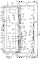
- the door- or window-frame is composed of a framework and a pane which are generally designated by the reference numerals 1 and 2 respectively.
- the framework 1 comprises two vertical jambs, respectively a hinging jamb 3 and an abutment jamb 4, which are connected at their lower and upper ends by horizontal rails 5 and 6.
- the jambs 3 and 4 and the rails 5 and 6 are provided by means of a profiled element which has, on the internal face of the framework, ridges for stiffening and for supporting sealing gaskets.
- the reference numerals 7 and 8 designate two ridges
- the reference numeral 9 designates a third ridge provided with a channel for accommodating a sealing gasket.
- the two ridges 7 and 8 are proximate to the abutment side of the pane 2 and delimit a channel 10 between them.
- the pane 2 can be hinged in a side-hung configuration to the jamb 3 or in a swing-down configuration to the lower rail 5.
- two hinges 11 and 12 each of which comprises a hinge pin 13 provided with a strip 14 by means of which it is fixed inside the channel 10 of the jamb 3, and a pivot 15 which protrudes upward.
- the second part of the hinges is applied to the pivot 15 of the hinges 11 and 12 and is constituted by a bush or tubular cap which is designated by the reference numeral 16 for the hinge 11 and by the reference numeral 17 for the hinge 12.
- Respective wings 18 and 19 protrude from the caps 16 and 17 and are folded at right angles complementarily with respect to the profile of the elements that compose the jamb of the pane 2 with which they are to be associated.
- an arm 20, constituted by a bar provided with a slot 21 which is open in an upward region, is fixed to the wing 18.
- the pane 2 is provided by means of tubular profiled elements and comprises two vertical uprights 22 and 23, respectively for abutment against the jamb 4 of the framework and for pivoting to the jamb 3.
- the opposite ends of the uprights 22 and 23 are connected by a lower horizontal rail 24 and by an upper horizontal rail 25.
- the uprights 22 and 23 and the rails 24 and 25 of the pane 2 have an external perimetric face 26 which is perpendicular to the plane of the pane and from which a perimetric flange 27 for resting against the framework 1 protrudes outward.
- a continuous slot 28 is formed in the face 26 along the uprights and the rails.
- a rod 29 is slidingly accommodated in the portion of the slot 28 that runs from the level of the hinge 11 in an upward direction along the upright 23 for the hinging of the pane 2, and a strip or flexible band 30 is connected to the top of said rod and lies in the horizontal portion of the slot 28 that runs along the upper rail 25.
- An elongated member 31 is fixed in the portion of the slot 28 that protrudes downward from the hinge 11, and a bracket 32 is fixed to its lower end; the arm 20 is articulated in said bracket by means of a pivot 33.
- the arm 20 is in sliding contact with the longitudinal member 31 so as to oscillate on a plane at right angles to the plane of the pane 2.
- the bracket 32 is fixed in the slot 28 of the lower rail 24 proximate to the corner formed with the hinging upright 23 and can be accommodated in the interspace formed between the rails 24 and 25 of the pane 2 and of the framework 1 when the pane is in the closed position.
- the bracket 32 has a length which affects only a portion of the lower rail. However, it can be longer and can affect most of the length of the lower rail.
- the pivot 33 constitutes the axis for the hinging of the pane 2 with respect to the framework 1 when the pane is to be openable with a swing-down movement.
- the arm 20 is surrounded by a U-shaped wing 34 which is fixed to the upright 23 and is open on the opposite side with respect to the flange 27.
- the wing 34 supports the arm 20 and allows the pane 2 to swing outward during rotation into the swing-down position.
- the end of the flexible band 30 that lies furthest from the rod 29 is fastened to an additional rod 35 which is slidingly accommodated in the portion of the slot 28 that descends from the top of the abutment upright 22.
- the lower end of the rod 35 is operatively associated with a conventional actuation element, generally designated by the reference numeral 36, which comprises an actuation handle 37.
- a rod 38 is also operatively associated with the element 36 and is slidingly accommodated in the portion of the slot 28 that descends from the element 36 toward the lower end of the abutment upright 22.
- the actuation element 36 is described concisely hereinafter for the sake of completeness without delving into the details of the internal elements since they are of a known type and are not pertinent to the present invention.
- the actuation element 36 is preset so as to assume three operating positions which correspond to the orientation of the handle 37.
- the pane 2 can rotate freely in the side-hung configuration.
- the handle 37 is rotated upward, the pane 2 can rotate freely in the swing-down configuration.
- the handle 37 is turned downward, the pane is locked in the closed position.
- the handle 37 can be actuated only after the pane has been moved to the closed position in abutment against the framework 1. This is done to ensure that accidental actuation of the handle 37 while the pane 1 is in the side-hung or swing-down opening position cannot cause the disengagement of said pane from the hinges 11 and 12 and make it fall, with severe danger for nearby people.
- the actuation element 36 is provided with a mechanical sensor 39 which allows the handle to rotate only when the abutment upright 22 of the pane 2 rests against the abutment jamb 4 of the framework and a locator 40 fixed to the abutment jamb acts on the sensor 39.
- a characteristic of the door- or window-frame according to the present invention is constituted by the fact that the locator 40 is fixed to the internal face of the abutment jamb 4 and is constituted by a tab which is shaped so as to form, together with said face, a slot 41. Access to the sensor 39 in the position in which the pane 2 is open is prevented by a plate 42 which is shaped so that when the pane 2 is adjacent to the framework 1 the sensor 39 is actuated by the tab 40 while the plate 42 is accommodated in the slot 41.
- a laminar element hereinafter termed blade 43
- the length and the distance of the blade 43 with respect to the adjacent face of the upright 23 allow the blade 43, through the actuation of the rod 29 transmitted by the handle 37 through the rod 35 and the flexible band 30, to descend until it lies behind the wing 19 of the tubular cap 17 and locks it in the corner of the upright formed by the face 26 and by the flange 27.
- a pivot 44 is fixed to the lower end of the rod 28 and is aligned with the slot 21 of the arm 20 so as to be able to engage therein when the rod 28 is actuated so as to descend.
- the rods 35 and 38 are provided with two respective pivots 45 and 46 which protrude outward from the outer face 26 of the abutment upright 22.
- the pivot 45 In the closed position of the pane 2 and by actuating the rod 35 upward, the pivot 45 is adapted to engage behind a tooth 47 of a plate 48 (see Figures 1 and 5) which is fixed to the internal face of the abutment jamb 4 of the framework 1.
- the pivot 46 in the closed position of the pane 2 and by actuating the rod 38 downward, can engage the front opening 49 of an L-shaped element 50 which is fixed in the corner of the framework 1 formed by the abutment jamb 4 and by the lower rail 5.
- the opening 49 has a certain length and is connected to a channel 51 formed in the vertical side of the L-shaped element 50.
- the L-shaped element 50 has a horizontal portion which lies above the channel 10 of the lower rail 5 and supports a roller 52 which acts as a support for the pane 2, which rests thereon with a plate 53 interposed when the pane is closed.
- a block 54 which is adapted to engage in a sleeve 55 which is rigidly coupled to the upright 22 when the rod 35 is actuated upward.
- the oscillation of the pane 2 in the swing-down position is determined by two arms 56 and 57 whose upper ends are articulated, by means of pivots 58 and 59, in brackets 60 and 61 which are rigidly coupled to the internal faces of the jambs 3 and 4 of the framework and have downward extensions 62 and 63 which act as a locator for the arms 56 and 57, keeping them vertical and allowing them to rotate only toward the pane 2.
- the arms 56 and 57 have seats 64 and 65 which are open toward each other.
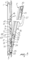
- the seat 64 of the arm 56 (see Figures 2 and 3 in particular) has an opening 66 formed in the edge that makes contact with the extension 62.
- the opening 66 forms, in the seat 64, a recess 67 toward the free end of the arm 56.
- the seat 65 of the arm 57 has, on the edge that lies adjacent to the extension 63, an opening 68 which forms a recess 69.
- a support 70 is fixed to the jamb 4, above the bracket 61, and supports a free roller 71 on which a ledge 72, fixed to the outer face 26 of the abutment upright 22 of the pane, is meant to rest during the closure of the pane 2.
- the seat 64 is arranged on the jamb 3 of the framework 1 so that it can be engaged by a pivot 73 during the rotation of the pane 2 in the closed position.
- the pivot 73 is rigidly coupled to a block 74 which is fixed in a straddling arrangement above the rod 29 guided in the portion of the slot 28 that lies inside the jamb 3.
- a pivot 75 is fixed to the rod 38 and is adapted to engage the seat 65 of the arm 57 in order to engage said arm when the rod 38 is actuated in the direction in which the pivot 75 descends into the recess 69.
- the pivot 75 is at a lower level than the pivot 73 and the pivots 58 and 59 for the articulation of the arms 56 and 57 are coaxial, the arm 57 is longer than the arm 56 in order to allow the pivots 73 and 75 to engage the recesses 67 and 69 simultaneously despite assuming different inclinations with respect to the jambs 3 and 4 (see Figures 4 and 5).
- the described door- or window-frame is opened and closed as follows.
- the actuation element 36 being protected by the plate 42, prevents accidental actuation of the handle 37 from causing the sliding of the rods 38, 35 and 29 and the disengagement of the blade 43 from the wing 19 and of the pivot 44 from the slot 21 and therefore the disengagement of the pane 2 from the hinge pins because said pane is no longer supported by the retaining action of the blade 43 and of the pivot 44.
- the pivots 73 and 75 engage the seats 64 and 65, respectively, of the arms 56 and 57, while the pivot 46 engages the opening 49 of the L-shaped element 50.
- the pivot 73 directly enters the seat 64
- the pivot 75 enters the seat 65 through the opening 68 of the front edge of the arm 57.
- Figure 1 illustrates with crossed rectangles the position of the pivots 73, 75 and 49 with respect to the openings 66, 68 and 49. As clearly noticeable, the pivots can perform an upward stroke without making contact with the edges of the openings.
- the handle 37 is released, allowing it to be turned into the position for closing the pane or to be preset for swing-down opening.
- the handle 37 is turned downward so as to produce the upward sliding, in the direction A1, of the rods 38 and 35 and the downward sliding, in the direction A2, of the rod 29.
- the pivots 46 and 75 slide in the openings 49 and 68 while the pivot 45 engages behind the tooth 47 of the plate 48 which is fixed to the jamb 4.
- the blade 43 and the pivot 44 also perform a further downward stroke in the direction A2 which ensures firmer locking of the wing 19 and of the arm 20.
- the arms 56, 57 can oscillate freely about the pivots 58 and 59, the retention of the pane 2 in the closed position is determined by the engagement of the pivot 45 behind the tooth 47 of the plate 48, while the engagement of the pivots 46, 73 and 75 in the openings 49, 64 and 65 has no retaining effect.
- the handle 37 is actuated upward.
- the rods 35 and 38 slide downward in the direction B1 and the rod 29 slides upward in the direction B2.
- the pivot 45 remains disengaged from the tooth 47 of the plate 48 while the pivot 46 enters the channel 51 until it is substantially aligned with the axis of the articulation pivot 33, thus providing the pivoting of the pane 2 about a lower horizontal axis.
- the pane 2 Since the pane 2 is now free from peripheral engagements except for the lower articulation of the pivots 46 and 33, the pane can be swung down. It should be noted that during this swing-down oscillation the elongated member 31 rotates with respect to the arm 20 and the pivots 73 and 75 raise the arms 56 and 57 until they abut in the recesses 67 and 69, determining the opening angle of the pane (see Figures 4 and 5).
- a fundamental prerogative of the described door- or window-frame is the fact that the hinges 11 and 12 remain attached to the framework 1, so that the pane 2, in the open position, has no perimetric protrusions.
- the lack of protrusions is an evident aesthetic improvement of the door- or window-frame.
- a substantial advantage of the described door- or window-frame is the adoption of the two arms 56 and 57 as elements for stopping the pane 2 in the swung-down position. Since said arms only have to perform an oscillating movement in order to reach the stop position and are subjected only to traction forces, they are not subject to jamming as occurs in the devices used so far, which by interacting between the upper rails of the pane and of the frame must take into account the arc-like path covered by the upper rail of the pane and accordingly provide plays or rods which are capable of flexing in order to compensate for the nonlinear movement of the upper rail 25.
- Another advantage offered by the door- or window-frame according to the present invention is the possibility to provide a plurality of pane articulation hinges.
- the hinges can in fact be fitted on the upright 27 of the framework and can be connected to the pane by means of a matching number of blades 43 which are rigidly coupled to said rod 29.
Landscapes
- Engineering & Computer Science (AREA)
- Mechanical Engineering (AREA)
- Wing Frames And Configurations (AREA)
- Hinges (AREA)
- Door And Window Frames Mounted To Openings (AREA)
Applications Claiming Priority (2)
| Application Number | Priority Date | Filing Date | Title |
|---|---|---|---|
| IT98BO000500 IT1304481B1 (it) | 1998-08-19 | 1998-08-19 | Serramento con anta apribile a bandiera o a ribalta. |
| ITBO980500 | 1998-08-19 |
Publications (2)
| Publication Number | Publication Date |
|---|---|
| EP0980952A2 true EP0980952A2 (de) | 2000-02-23 |
| EP0980952A3 EP0980952A3 (de) | 2001-06-27 |
Family
ID=11343372
Family Applications (1)
| Application Number | Title | Priority Date | Filing Date |
|---|---|---|---|
| EP99115047A Withdrawn EP0980952A3 (de) | 1998-08-19 | 1999-08-04 | Tür- oder Fensterrahmen mit seitlich oder unten angelenktem Flügel |
Country Status (2)
| Country | Link |
|---|---|
| EP (1) | EP0980952A3 (de) |
| IT (1) | IT1304481B1 (de) |
Cited By (1)
| Publication number | Priority date | Publication date | Assignee | Title |
|---|---|---|---|---|
| EP4083360A3 (de) * | 2021-04-27 | 2023-01-18 | SCHÜCO International KG | Drehkippfenster und beschlaganordnung |
Family Cites Families (3)
| Publication number | Priority date | Publication date | Assignee | Title |
|---|---|---|---|---|
| DE1232851B (de) * | 1959-12-23 | 1967-01-19 | Ver Baubeschlag Gretsch Co | Ausstellvorrichtung fuer Kipp-Schwenkfluegel von Fenstern, Tueren od. dgl. |
| DE8201880U1 (de) * | 1982-01-27 | 1982-06-16 | Siegenia-Frank Kg, 5900 Siegen | Drehkippfenster, drehkipptuer od.dgl. mit einem seitenscharnier und einem ausstellarm |
| DE19538817C2 (de) * | 1995-10-18 | 1998-09-10 | Georg Schottenhamml | Beschlag für Fenster sowie Dreh-Kipp-Fenster mit einem solchen Beschlag |
-
1998
- 1998-08-19 IT IT98BO000500 patent/IT1304481B1/it active
-
1999
- 1999-08-04 EP EP99115047A patent/EP0980952A3/de not_active Withdrawn
Cited By (1)
| Publication number | Priority date | Publication date | Assignee | Title |
|---|---|---|---|---|
| EP4083360A3 (de) * | 2021-04-27 | 2023-01-18 | SCHÜCO International KG | Drehkippfenster und beschlaganordnung |
Also Published As
| Publication number | Publication date |
|---|---|
| EP0980952A3 (de) | 2001-06-27 |
| ITBO980500A1 (it) | 2000-02-19 |
| IT1304481B1 (it) | 2001-03-19 |
Similar Documents
| Publication | Publication Date | Title |
|---|---|---|
| US4364201A (en) | Full-opening window linkage assembly | |
| US4428153A (en) | Recessed astragal for double door | |
| US4420905A (en) | Closure hardware | |
| US6311439B1 (en) | Window frame | |
| US5237775A (en) | Sliding mechanism for window constructions | |
| US4035953A (en) | Hinge and hinge and pivot arrangement | |
| US20130212947A1 (en) | Load Bearing Structural Closure System | |
| US4055024A (en) | Roof window arrangement | |
| US5289656A (en) | Geared casement window hinges | |
| US20190264485A1 (en) | Upwardly Pivoted Window with Spring Biased Sash | |
| US7793463B1 (en) | Plantation style security shutters | |
| EP3042017B1 (de) | Winddichtes fenster oder tür mit mindestens einem schiebeflügel | |
| EP2280143B1 (de) | Gelenkbeschlag für ein Drehfenster | |
| PL194844B1 (pl) | Dwuskrzydłowe drzwi, zwłaszcza drzwi przeciwpożarowe | |
| EP0980952A2 (de) | Tür- oder Fensterrahmen mit seitlich oder unten angelenktem Flügel | |
| SK10332001A3 (sk) | Okno alebo dvere | |
| CN106948694A (zh) | 用于平开翻转窗和翻转平开窗的隐藏式铰链及配备其的窗户 | |
| US3571976A (en) | Door and window arrangement | |
| PL242906B1 (pl) | Okno dachowe dwuskrzydłowe | |
| EP2821575A2 (de) | Verbessertes Schwenkfenster mit mindestens einer Hilfsvorrichtung zum Öffnen und einem Feststeller | |
| JPH0658038A (ja) | 全開放型ドア | |
| GB2247907A (en) | Sliding window | |
| EP4545739B1 (de) | Begrenzungsanordnung zur begrenzung der öffnung einer schiebetür oder eines schiebefensters | |
| GB2045844A (en) | Cladding for reversible sky-light | |
| RU2078895C1 (ru) | Ворота подъемно-поворотные |
Legal Events
| Date | Code | Title | Description |
|---|---|---|---|
| PUAI | Public reference made under article 153(3) epc to a published international application that has entered the european phase |
Free format text: ORIGINAL CODE: 0009012 |
|
| AK | Designated contracting states |
Kind code of ref document: A2 Designated state(s): AT BE CH CY DE DK ES FI FR GB GR IE IT LI LU MC NL PT SE |
|
| AX | Request for extension of the european patent |
Free format text: AL;LT;LV;MK;RO;SI |
|
| PUAL | Search report despatched |
Free format text: ORIGINAL CODE: 0009013 |
|
| AK | Designated contracting states |
Kind code of ref document: A3 Designated state(s): AT BE CH CY DE DK ES FI FR GB GR IE IT LI LU MC NL PT SE |
|
| AX | Request for extension of the european patent |
Free format text: AL;LT;LV;MK;RO;SI |
|
| AKX | Designation fees paid | ||
| REG | Reference to a national code |
Ref country code: DE Ref legal event code: 8566 |
|
| STAA | Information on the status of an ep patent application or granted ep patent |
Free format text: STATUS: THE APPLICATION IS DEEMED TO BE WITHDRAWN |
|
| 18D | Application deemed to be withdrawn |
Effective date: 20011228 |