EP0981177A2 - Sende- und Empfangsvorrichtung - Google Patents
Sende- und Empfangsvorrichtung Download PDFInfo
- Publication number
- EP0981177A2 EP0981177A2 EP99202590A EP99202590A EP0981177A2 EP 0981177 A2 EP0981177 A2 EP 0981177A2 EP 99202590 A EP99202590 A EP 99202590A EP 99202590 A EP99202590 A EP 99202590A EP 0981177 A2 EP0981177 A2 EP 0981177A2
- Authority
- EP
- European Patent Office
- Prior art keywords
- antenna
- transmitting
- receiving device
- frequency range
- frequency
- Prior art date
- Legal status (The legal status is an assumption and is not a legal conclusion. Google has not performed a legal analysis and makes no representation as to the accuracy of the status listed.)
- Ceased
Links
Images

Classifications
-
- H—ELECTRICITY
- H04—ELECTRIC COMMUNICATION TECHNIQUE
- H04B—TRANSMISSION
- H04B1/00—Details of transmission systems, not covered by a single one of groups H04B3/00 - H04B13/00; Details of transmission systems not characterised by the medium used for transmission
- H04B1/38—Transceivers, i.e. devices in which transmitter and receiver form a structural unit and in which at least one part is used for functions of transmitting and receiving
-
- H—ELECTRICITY
- H01—ELECTRIC ELEMENTS
- H01Q—ANTENNAS, i.e. RADIO AERIALS
- H01Q9/00—Electrically-short antennas having dimensions not more than twice the operating wavelength and consisting of conductive active radiating elements
- H01Q9/04—Resonant antennas
- H01Q9/0485—Dielectric resonator antennas
-
- H—ELECTRICITY
- H01—ELECTRIC ELEMENTS
- H01Q—ANTENNAS, i.e. RADIO AERIALS
- H01Q1/00—Details of, or arrangements associated with, antennas
- H01Q1/12—Supports; Mounting means
- H01Q1/22—Supports; Mounting means by structural association with other equipment or articles
- H01Q1/24—Supports; Mounting means by structural association with other equipment or articles with receiving set
- H01Q1/241—Supports; Mounting means by structural association with other equipment or articles with receiving set used in mobile communications, e.g. GSM
- H01Q1/242—Supports; Mounting means by structural association with other equipment or articles with receiving set used in mobile communications, e.g. GSM specially adapted for hand-held use
-
- H—ELECTRICITY
- H01—ELECTRIC ELEMENTS
- H01Q—ANTENNAS, i.e. RADIO AERIALS
- H01Q1/00—Details of, or arrangements associated with, antennas
- H01Q1/52—Means for reducing coupling between antennas; Means for reducing coupling between an antenna and another structure
- H01Q1/521—Means for reducing coupling between antennas; Means for reducing coupling between an antenna and another structure reducing the coupling between adjacent antennas
- H01Q1/525—Means for reducing coupling between antennas; Means for reducing coupling between an antenna and another structure reducing the coupling between adjacent antennas between emitting and receiving antennas
Definitions
- the invention relates to a transmitting and receiving device for at least two Frequency ranges in which at least one antenna arrangement for one Frequency range is provided.
- the invention relates to a mobile radio device with such a transmission and Receiving device.
- FIG. 1 shows a schematic circuit diagram of a transmit and Receiving device in a mobile radio telephone.
- An antenna 1 is used here to send and receive data.
- a duplex filter 4 can be used for this, which consists of two sharp-edged ones Bandpass filters 5 and 6 exist.
- Bandpass filters 5 and 6 exist.
- the communication radio includes a housing in which a transmitter and a receiver are housed.
- the communication radio can send and receive at the same time.
- a first antenna is with the Receiver and a second antenna connected to the transmitter, the transmitter and the receiver is working in different frequencies.
- the different ones Frequencies tuned antennas are each connected to the receiver via a filter or connected to the transmitter.
- the object of the invention is to provide a better transmitting and receiving device with easier separation of different frequency ranges.
- the object of the invention is achieved in that at least one dielectric Resonator antenna (DRA) provided to form at least one antenna arrangement is.
- a dielectric resonator antenna is due to its physical properties only functional in a narrow frequency range around their resonance frequency. Therefore is an antenna arrangement formed from a dielectric resonator antenna narrow band, with which a very good separation of different frequency ranges, e.g. B. for sending and receiving.
- DRA dielectric Resonator antenna
- a first antenna for reception is in a first frequency range and a second antenna for transmission in a second Frequency range provided.
- This embodiment is particularly suitable for Use in a transmission system with different frequency ranges for Send and receive, such as GSM900, GSM1800, DECT or similar.
- Another advantageous embodiment of the invention results when a first antenna for receiving (or transmitting) in a frequency range in a first transmission system and a second antenna for receiving (or transmitting) in a frequency range in a second transmission system is provided.
- the Transmitting and receiving device in different transmission systems simultaneously operate.
- more than two antennas can also be provided which allows more frequency ranges to be used.
- the object of the invention is achieved by a mobile radio device with a Sending and receiving device solved, in which at least one dielectric resonator antenna (DRA) is provided to form at least one antenna arrangement.
- DRA dielectric resonator antenna
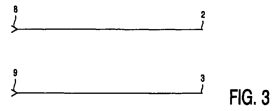
- FIG. 3 shows a transmitting and receiving device that has a receiving channel 2 with a receiving antenna 8 and a transmitting channel 3 with a transmitting antenna 9 contains.
- Dielectric resonator antennas are used as receiving antenna 8 and transmitting antenna 9 (DRA), which is characterized by a high degree of miniaturization and the Characterize the possibility of surface mounting (SMD technology). Besides, one is DRA due to its physical properties very narrowband (only in one narrow frequency range around the resonance frequency functional).
- the dielectric Resonator antenna consists of a dielectric body (usually made of a ceramic), the is attached to a metallic surface. However, other antennas can also be used with such properties as such. B.
- a microstrip antenna in the on a (mostly dielectric) substrate a conductive structure as a radiating element is applied while a conductive layer on the back of the substrate Forms reference potential.
- the transmitting antenna 9 is on the transmitting frequency and the receiving antenna 8 tuned to the reception frequency. Because of the narrow-band properties are no further filters to separate receive channel 8 and transmit channel 9 required.
- the tuning to the corresponding frequency ranges can be done by special design of the radiating element, the dielectric substrate (resonators) or how the signal is fed.
- the signal is mostly about a coaxial line or a microstrip line supplied.
- a transmitting and receiving device with a receiving antenna 8 and one Transmitting antenna 9, which are each realized by means of a dielectric resonator antenna, significantly narrower bandwidths can be achieved.
- a limitation of the respective bandwidth is important. This means that a channel is disturbed by a signal prevented in another channel (for a different frequency range). Since at the The transmitting and receiving device according to the invention already uses the antennas 8 and 9 are very narrow-band, there is no need for additional filters.
- FIG. 4 shows a DRA 10 in the basic form to be regarded as an example.
- other shapes are also possible, such as cylindrical or spherical geometries.
- Dielectric resonator antennas are resonant components that only work in a narrow band around one of their resonance frequencies.
- the resonance frequency of the DRA 10 depends on the dimensions of the DRA 10. In order to obtain the smallest possible dimensions, the lowest resonance (Te 2 111 mode) is therefore usually used.
- the DRA 10 shown is realized by a cuboid with the dimensions 40x40x7.6 mm 3 from a (Ba, Nd, Gd) TiO 3 ) ceramic.
- the DRA 10 operates at an operating frequency of 1GHz in its lowest resonance (TE 2 111 mode). With other dimensions, the resonance frequency is shifted.
- Typical dimensions for a DRA 10 with an operating frequency of approximately 1.9 GHz (DECT) are approximately 20x20x6mm 3 .
- Such a transmitting and receiving device is particularly suitable for the mobile radio sector, with different frequency ranges for sending and receiving are used (e.g. according to GSM the frequency ranges 890-915 MHz and 935-960 MHz for sending and receiving).
- Cordless phones are also behind DECT, mobile radio devices for DCS1800 and PHS as well as devices for other transmission systems, which use different frequency ranges in one device, possible areas of application. Combined devices in multiple transmission systems are also conceivable work.
Landscapes
- Engineering & Computer Science (AREA)
- Computer Networks & Wireless Communication (AREA)
- Signal Processing (AREA)
- Transceivers (AREA)
- Waveguide Aerials (AREA)
- Details Of Aerials (AREA)
- Support Of Aerials (AREA)
Abstract
Description
- Figur 1:
- ein schematisches Schaltbild einer Sende- und Empfangsvorrichtung mit einem Duplexfilter,
- Figur 2:
- ein schematisches Schaltbild einer Sende- und Empfangsvorrichtung mit einem elektronischen Schalter und
- Figur 3:
- ein schematisches Schaltbild einer erfindungsgemäßen Sende- und Empfangsvorrichtung.
- Figur 4:
- eine dielektrische Resonatorantenne zur Verwendung in einer erfindungsgemäßen Sende- und Empfangsvorrichtung.
Claims (5)
- Sende- und Empfangsvorrichtung für wenigstens zwei Frequenzbereiche, bei der wenigstens eine Antennenanordnung (8, 9) für jeweils einen Frequenzbereich vorgesehen ist,
dadurch gekennzeichnet,
daß wenigstens eine dielektrische Resonatorantenne (DRA) zur Bildung wenigstens einer Antennenanordnung (8, 9) vorgesehen ist. - Sende- und Empfangsvorrichtung nach Anspruch 1,
dadurch gekennzeichnet,
daß eine erste Antenne (8) zum Empfang in einem ersten Frequenzbereich und eine zweite Antenne (9) zum Senden in einem zweiten Frequenzbereich vorgesehen ist. - Sende- und Empfangsvorrichtung nach Anspruch 1,
dadurch gekennzeichnet,
daß eine erste Antenne (8) zum Empfang in einem Frequenzbereich in einem ersten Übertragungssystem und eine zweite Antenne (9) zum Empfang in einem Frequenzbereich in einem zweiten Übertragungssystem vorgesehen ist. - Sende- und Empfangsvorrichtung nach Anspruch 1,
dadurch gekennzeichnet,
daß eine erste Antenne (8) zum Senden in einem Frequenzbereich in einem ersten Übertragungssystem und eine zweite Antenne (9) zum Senden in einem Frequenzbereich an einem zweiten Übertragungssystem vorgesehen ist. - Mobilfunkgerät mit einer Sende- und Empfangsvorrichtung für wenigstens zwei Frequenzbereiche, bei der wenigstens eine Antennenanordnung (8, 9) für jeweils einen Frequenzbereich vorgesehen ist,
dadurch gekennzeichnet,
daß wenigstens eine dielektrische Resonatorantenne (DRA) zur Bildung wenigstens einer Antennenanordnung (8, 9) vorgesehen ist.
Applications Claiming Priority (2)
| Application Number | Priority Date | Filing Date | Title |
|---|---|---|---|
| DE19836952A DE19836952A1 (de) | 1998-08-17 | 1998-08-17 | Sende- und Empfangsvorrichtung |
| DE19836952 | 1998-08-17 |
Publications (2)
| Publication Number | Publication Date |
|---|---|
| EP0981177A2 true EP0981177A2 (de) | 2000-02-23 |
| EP0981177A3 EP0981177A3 (de) | 2001-05-02 |
Family
ID=7877580
Family Applications (1)
| Application Number | Title | Priority Date | Filing Date |
|---|---|---|---|
| EP99202590A Ceased EP0981177A3 (de) | 1998-08-17 | 1999-08-09 | Sende- und Empfangsvorrichtung |
Country Status (8)
| Country | Link |
|---|---|
| US (1) | US6314276B1 (de) |
| EP (1) | EP0981177A3 (de) |
| JP (1) | JP2000077924A (de) |
| KR (1) | KR20000017327A (de) |
| CN (1) | CN1245368A (de) |
| DE (1) | DE19836952A1 (de) |
| SG (1) | SG74745A1 (de) |
| TW (1) | TW486890B (de) |
Cited By (1)
| Publication number | Priority date | Publication date | Assignee | Title |
|---|---|---|---|---|
| GB2387995A (en) * | 2002-04-23 | 2003-10-29 | Hutchison Whampoa Three G Ip | Multi-mode portable telecommunication terminal with Dielectric Resonator Antenna |
Families Citing this family (19)
| Publication number | Priority date | Publication date | Assignee | Title |
|---|---|---|---|---|
| KR100406284B1 (ko) * | 2001-04-25 | 2003-11-14 | 현우마이크로 주식회사 | 벌크(Bulk) 형태의 유전체를 이용한아이엠티-2000(IMT-2000) 단말기용 소형 안테나 장치 |
| JP2004072374A (ja) * | 2002-08-06 | 2004-03-04 | Casio Comput Co Ltd | 電子スチルカメラ及び撮像方法 |
| US7999749B2 (en) * | 2008-10-23 | 2011-08-16 | Sony Ericsson Mobile Communications Ab | Antenna assembly |
| US11367959B2 (en) | 2015-10-28 | 2022-06-21 | Rogers Corporation | Broadband multiple layer dielectric resonator antenna and method of making the same |
| US10601137B2 (en) | 2015-10-28 | 2020-03-24 | Rogers Corporation | Broadband multiple layer dielectric resonator antenna and method of making the same |
| US10374315B2 (en) | 2015-10-28 | 2019-08-06 | Rogers Corporation | Broadband multiple layer dielectric resonator antenna and method of making the same |
| US10355361B2 (en) | 2015-10-28 | 2019-07-16 | Rogers Corporation | Dielectric resonator antenna and method of making the same |
| US10476164B2 (en) | 2015-10-28 | 2019-11-12 | Rogers Corporation | Broadband multiple layer dielectric resonator antenna and method of making the same |
| US11876295B2 (en) | 2017-05-02 | 2024-01-16 | Rogers Corporation | Electromagnetic reflector for use in a dielectric resonator antenna system |
| US11283189B2 (en) | 2017-05-02 | 2022-03-22 | Rogers Corporation | Connected dielectric resonator antenna array and method of making the same |
| KR102312067B1 (ko) | 2017-06-07 | 2021-10-13 | 로저스코포레이션 | 유전체 공진기 안테나 시스템 |
| US11616302B2 (en) | 2018-01-15 | 2023-03-28 | Rogers Corporation | Dielectric resonator antenna having first and second dielectric portions |
| US10892544B2 (en) | 2018-01-15 | 2021-01-12 | Rogers Corporation | Dielectric resonator antenna having first and second dielectric portions |
| US10910722B2 (en) | 2018-01-15 | 2021-02-02 | Rogers Corporation | Dielectric resonator antenna having first and second dielectric portions |
| US10833417B2 (en) | 2018-07-18 | 2020-11-10 | City University Of Hong Kong | Filtering dielectric resonator antennas including a loop feed structure for implementing radiation cancellation |
| US11552390B2 (en) | 2018-09-11 | 2023-01-10 | Rogers Corporation | Dielectric resonator antenna system |
| US11031697B2 (en) | 2018-11-29 | 2021-06-08 | Rogers Corporation | Electromagnetic device |
| CN113169455A (zh) | 2018-12-04 | 2021-07-23 | 罗杰斯公司 | 电介质电磁结构及其制造方法 |
| US11482790B2 (en) | 2020-04-08 | 2022-10-25 | Rogers Corporation | Dielectric lens and electromagnetic device with same |
Family Cites Families (7)
| Publication number | Priority date | Publication date | Assignee | Title |
|---|---|---|---|---|
| SE462191B (sv) * | 1988-01-18 | 1990-05-14 | Allgon Antenn Ab | Anordning foer filterverkan vid antenner foer kommunikationsradioapparater och traadloesa telefoner |
| US5557293A (en) | 1995-01-26 | 1996-09-17 | Motorola, Inc. | Multi-loop antenna |
| JP3243595B2 (ja) * | 1995-10-31 | 2002-01-07 | 株式会社トーキン | マルチバンドアンテナ及びそれを用いたマルチバンド携帯無線機 |
| CA2173679A1 (en) | 1996-04-09 | 1997-10-10 | Apisak Ittipiboon | Broadband nonhomogeneous multi-segmented dielectric resonator antenna |
| FR2754942B1 (fr) | 1996-10-23 | 1999-01-08 | Thomson Csf | Systeme antennaire pour poste radiotelephone portatif |
| US6043786A (en) * | 1997-05-09 | 2000-03-28 | Motorola, Inc. | Multi-band slot antenna structure and method |
| US6147647A (en) * | 1998-09-09 | 2000-11-14 | Qualcomm Incorporated | Circularly polarized dielectric resonator antenna |
-
1998
- 1998-08-17 DE DE19836952A patent/DE19836952A1/de not_active Ceased
-
1999
- 1999-07-12 TW TW088111783A patent/TW486890B/zh not_active IP Right Cessation
- 1999-08-06 US US09/369,541 patent/US6314276B1/en not_active Expired - Fee Related
- 1999-08-09 EP EP99202590A patent/EP0981177A3/de not_active Ceased
- 1999-08-13 CN CN99117974A patent/CN1245368A/zh active Pending
- 1999-08-16 SG SG1999003976A patent/SG74745A1/en unknown
- 1999-08-16 KR KR1019990033640A patent/KR20000017327A/ko not_active Withdrawn
- 1999-08-16 JP JP11230030A patent/JP2000077924A/ja active Pending
Cited By (2)
| Publication number | Priority date | Publication date | Assignee | Title |
|---|---|---|---|---|
| GB2387995A (en) * | 2002-04-23 | 2003-10-29 | Hutchison Whampoa Three G Ip | Multi-mode portable telecommunication terminal with Dielectric Resonator Antenna |
| GB2387995B (en) * | 2002-04-23 | 2006-01-25 | Hutchison Whampoa Three G Ip | Improved portable telecommunication terminal |
Also Published As
| Publication number | Publication date |
|---|---|
| US6314276B1 (en) | 2001-11-06 |
| CN1245368A (zh) | 2000-02-23 |
| TW486890B (en) | 2002-05-11 |
| SG74745A1 (en) | 2000-08-22 |
| JP2000077924A (ja) | 2000-03-14 |
| KR20000017327A (ko) | 2000-03-25 |
| DE19836952A1 (de) | 2000-04-20 |
| EP0981177A3 (de) | 2001-05-02 |
Similar Documents
| Publication | Publication Date | Title |
|---|---|---|
| EP0981177A2 (de) | Sende- und Empfangsvorrichtung | |
| DE60110827T2 (de) | Verfahren zur kanalfrequenzzuteilung für hf- und mikrowellenduplexer | |
| DE69835246T2 (de) | Doppelresonanzantennenstruktur für mehrere Frequenzbereiche | |
| DE60109608T2 (de) | Antenne und funkgerät mit einer derartigen antenne | |
| EP1204160B1 (de) | Mehrband-Mikrowellenantenne | |
| EP0484454B1 (de) | Sende- und/oder empfangsanordnung für tragbare geräte | |
| DE10150159B4 (de) | Impedanzanpassungsschaltung für einen Mehrband-Leisungsverstärker | |
| DE60115131T2 (de) | Chip-Antennenelement und dieses aufweisendes Nachrichtenübertragungsgerät | |
| DE60306456T2 (de) | Mäanderförmige Mehrbandantenne | |
| EP1289053A2 (de) | Schaltungsplatine und SMD-Antenne hierfür | |
| DE10015583A1 (de) | Sende-/Empfangsvorrichtung | |
| DE19837266A1 (de) | Dielektrische Resonatorantenne | |
| DE10223497A1 (de) | Dualbandantenne mit drei Resonatoren | |
| DE10052711A1 (de) | Multiband-Endgerät | |
| DE19961488A1 (de) | Antenne für ein Kommunikationsendgerät | |
| DE60310913T2 (de) | Verbesserungen in oder im zusammenhang mit drahtlosen endgeräten | |
| DE69523041T2 (de) | Streifenleitungsfilter, empfänger mit einem streifenleitungsfilter und verfahren zur abstimmung eines derartigen filters | |
| DE10015582B4 (de) | Antennenvorrichtung | |
| DE3751062T2 (de) | Filter, bestehend aus einer einbaubaren einheit mit mehreren resonatoren. | |
| DE10126624A1 (de) | Duplexer und mobile Kommunikationsvorrichtung unter Verwendung desselben | |
| EP1298447A2 (de) | GPS-Empfangsmodul | |
| DE10025431A1 (de) | Spiralförmige Antenne | |
| DE10137753A1 (de) | Mehrband-Funkantenne | |
| DE69527244T2 (de) | Antenne | |
| DE19822371B4 (de) | Antennenanordnung und Funkgerät |
Legal Events
| Date | Code | Title | Description |
|---|---|---|---|
| PUAI | Public reference made under article 153(3) epc to a published international application that has entered the european phase |
Free format text: ORIGINAL CODE: 0009012 |
|
| AK | Designated contracting states |
Kind code of ref document: A2 Designated state(s): DE FR GB IT |
|
| AX | Request for extension of the european patent |
Free format text: AL;LT;LV;MK;RO;SI |
|
| PUAL | Search report despatched |
Free format text: ORIGINAL CODE: 0009013 |
|
| AK | Designated contracting states |
Kind code of ref document: A3 Designated state(s): AT BE CH CY DE DK ES FI FR GB GR IE IT LI LU MC NL PT SE |
|
| AX | Request for extension of the european patent |
Free format text: AL;LT;LV;MK;RO;SI |
|
| RIC1 | Information provided on ipc code assigned before grant |
Free format text: 7H 01Q 9/04 A, 7H 01Q 1/52 B, 7H 01Q 1/24 B, 7H 01Q 21/28 B |
|
| 17P | Request for examination filed |
Effective date: 20011102 |
|
| AKX | Designation fees paid |
Free format text: DE FR GB IT |
|
| 17Q | First examination report despatched |
Effective date: 20020418 |
|
| RAP1 | Party data changed (applicant data changed or rights of an application transferred) |
Owner name: KONINKLIJKE PHILIPS ELECTRONICS N.V. Owner name: PHILIPS CORPORATE INTELLECTUAL PROPERTY GMBH |
|
| RAP1 | Party data changed (applicant data changed or rights of an application transferred) |
Owner name: KONINKLIJKE PHILIPS ELECTRONICS N.V. Owner name: PHILIPS INTELLECTUAL PROPERTY & STANDARDS GMBH |
|
| STAA | Information on the status of an ep patent application or granted ep patent |
Free format text: STATUS: THE APPLICATION HAS BEEN REFUSED |
|
| 18R | Application refused |
Effective date: 20040709 |