EP0981262A2 - Implant - Google Patents
Implant Download PDFInfo
- Publication number
- EP0981262A2 EP0981262A2 EP98121614A EP98121614A EP0981262A2 EP 0981262 A2 EP0981262 A2 EP 0981262A2 EP 98121614 A EP98121614 A EP 98121614A EP 98121614 A EP98121614 A EP 98121614A EP 0981262 A2 EP0981262 A2 EP 0981262A2
- Authority
- EP
- European Patent Office
- Prior art keywords
- housing
- energy source
- electrical energy
- implant
- potential
- Prior art date
- Legal status (The legal status is an assumption and is not a legal conclusion. Google has not performed a legal analysis and makes no representation as to the accuracy of the status listed.)
- Withdrawn
Links
Images


Classifications
-
- H—ELECTRICITY
- H01—ELECTRIC ELEMENTS
- H01M—PROCESSES OR MEANS, e.g. BATTERIES, FOR THE DIRECT CONVERSION OF CHEMICAL ENERGY INTO ELECTRICAL ENERGY
- H01M6/00—Primary cells; Manufacture thereof
- H01M6/50—Methods or arrangements for servicing or maintenance, e.g. for maintaining operating temperature
- H01M6/5005—Auxiliary electrodes
-
- A—HUMAN NECESSITIES
- A61—MEDICAL OR VETERINARY SCIENCE; HYGIENE
- A61N—ELECTROTHERAPY; MAGNETOTHERAPY; RADIATION THERAPY; ULTRASOUND THERAPY
- A61N1/00—Electrotherapy; Circuits therefor
- A61N1/18—Applying electric currents by contact electrodes
- A61N1/32—Applying electric currents by contact electrodes alternating or intermittent currents
- A61N1/36—Applying electric currents by contact electrodes alternating or intermittent currents for stimulation
- A61N1/372—Arrangements in connection with the implantation of stimulators
- A61N1/378—Electrical supply
-
- H—ELECTRICITY
- H01—ELECTRIC ELEMENTS
- H01M—PROCESSES OR MEANS, e.g. BATTERIES, FOR THE DIRECT CONVERSION OF CHEMICAL ENERGY INTO ELECTRICAL ENERGY
- H01M10/00—Secondary cells; Manufacture thereof
- H01M10/04—Construction or manufacture in general
- H01M10/0436—Small-sized flat cells or batteries for portable equipment
-
- H—ELECTRICITY
- H01—ELECTRIC ELEMENTS
- H01M—PROCESSES OR MEANS, e.g. BATTERIES, FOR THE DIRECT CONVERSION OF CHEMICAL ENERGY INTO ELECTRICAL ENERGY
- H01M10/00—Secondary cells; Manufacture thereof
- H01M10/42—Methods or arrangements for servicing or maintenance of secondary cells or secondary half-cells
- H01M10/48—Accumulators combined with arrangements for measuring, testing or indicating the condition of cells, e.g. the level or density of the electrolyte
-
- H—ELECTRICITY
- H01—ELECTRIC ELEMENTS
- H01M—PROCESSES OR MEANS, e.g. BATTERIES, FOR THE DIRECT CONVERSION OF CHEMICAL ENERGY INTO ELECTRICAL ENERGY
- H01M50/00—Constructional details or processes of manufacture of the non-active parts of electrochemical cells other than fuel cells, e.g. hybrid cells
- H01M50/10—Primary casings; Jackets or wrappings
- H01M50/102—Primary casings; Jackets or wrappings characterised by their shape or physical structure
- H01M50/103—Primary casings; Jackets or wrappings characterised by their shape or physical structure prismatic or rectangular
-
- H—ELECTRICITY
- H01—ELECTRIC ELEMENTS
- H01M—PROCESSES OR MEANS, e.g. BATTERIES, FOR THE DIRECT CONVERSION OF CHEMICAL ENERGY INTO ELECTRICAL ENERGY
- H01M50/00—Constructional details or processes of manufacture of the non-active parts of electrochemical cells other than fuel cells, e.g. hybrid cells
- H01M50/10—Primary casings; Jackets or wrappings
- H01M50/116—Primary casings; Jackets or wrappings characterised by the material
- H01M50/124—Primary casings; Jackets or wrappings characterised by the material having a layered structure
-
- H—ELECTRICITY
- H01—ELECTRIC ELEMENTS
- H01M—PROCESSES OR MEANS, e.g. BATTERIES, FOR THE DIRECT CONVERSION OF CHEMICAL ENERGY INTO ELECTRICAL ENERGY
- H01M50/00—Constructional details or processes of manufacture of the non-active parts of electrochemical cells other than fuel cells, e.g. hybrid cells
- H01M50/10—Primary casings; Jackets or wrappings
- H01M50/116—Primary casings; Jackets or wrappings characterised by the material
- H01M50/117—Inorganic material
- H01M50/119—Metals
-
- H—ELECTRICITY
- H04—ELECTRIC COMMUNICATION TECHNIQUE
- H04R—LOUDSPEAKERS, MICROPHONES, GRAMOPHONE PICK-UPS OR LIKE ACOUSTIC ELECTROMECHANICAL TRANSDUCERS; ELECTRIC HEARING AIDS; PUBLIC ADDRESS SYSTEMS
- H04R25/00—Electric hearing aids
- H04R25/60—Mounting or interconnection of hearing aid parts, e.g. inside tips, housings or to ossicles
- H04R25/602—Mounting or interconnection of hearing aid parts, e.g. inside tips, housings or to ossicles of batteries
-
- Y—GENERAL TAGGING OF NEW TECHNOLOGICAL DEVELOPMENTS; GENERAL TAGGING OF CROSS-SECTIONAL TECHNOLOGIES SPANNING OVER SEVERAL SECTIONS OF THE IPC; TECHNICAL SUBJECTS COVERED BY FORMER USPC CROSS-REFERENCE ART COLLECTIONS [XRACs] AND DIGESTS
- Y02—TECHNOLOGIES OR APPLICATIONS FOR MITIGATION OR ADAPTATION AGAINST CLIMATE CHANGE
- Y02E—REDUCTION OF GREENHOUSE GAS [GHG] EMISSIONS, RELATED TO ENERGY GENERATION, TRANSMISSION OR DISTRIBUTION
- Y02E60/00—Enabling technologies; Technologies with a potential or indirect contribution to GHG emissions mitigation
- Y02E60/10—Energy storage using batteries
-
- Y—GENERAL TAGGING OF NEW TECHNOLOGICAL DEVELOPMENTS; GENERAL TAGGING OF CROSS-SECTIONAL TECHNOLOGIES SPANNING OVER SEVERAL SECTIONS OF THE IPC; TECHNICAL SUBJECTS COVERED BY FORMER USPC CROSS-REFERENCE ART COLLECTIONS [XRACs] AND DIGESTS
- Y02—TECHNOLOGIES OR APPLICATIONS FOR MITIGATION OR ADAPTATION AGAINST CLIMATE CHANGE
- Y02P—CLIMATE CHANGE MITIGATION TECHNOLOGIES IN THE PRODUCTION OR PROCESSING OF GOODS
- Y02P70/00—Climate change mitigation technologies in the production process for final industrial or consumer products
- Y02P70/50—Manufacturing or production processes characterised by the final manufactured product
Definitions
- the present invention relates to an implant with an electrical energy consuming Arrangement and an electrical energy source having an anode and a cathode, which is coupled to the electrical energy consuming arrangement.
- Present such an implant is understood to mean an implant which either even consumes electrical energy and / or which with a separate, but also implanted, electrical energy consuming arrangement is coupled.
- the performance of the electrical energy source provided in the implant be it as a primary or a secondary cell, to be able to predict and on the other hand processes damaging the individual electrodes, such as in particular during charging processes an electrical energy source designed as a secondary cell can occur,
- the electrodes should be considered with regard to certain parameters such as current and Voltage are monitored.
- the electrodes of the electrical energy source cannot be used independently or individually observe and control. Rather, they are outside the energy source measurable parameters of current and voltage always on the entire combination of electrodes provided in the electrical energy source. During a measurement these parameters are generally relied upon for the electrodes to discharge, have predictable properties when idle and possibly when charging. Such a measurement can, however, be different due to the electrodes running simultaneously polarizing processes are falsified and then only allowed to a limited extent and with detailed knowledge of these processes under the current boundary conditions concludes about the current state of the electrical energy source.
- the equilibrium potentials of the two active electrodes due to the existing internal resistance more negative (negative electrode) and more positive (positive electrode) potentials shifted.
- the internal resistances are made up of ohmic and non-ohmic parts together.
- Ohmic components usually concern contact and electrolyte resistances.
- Non-ohmic components are due to the nature of the electrodes and those on the electrodes given electrochemical processes.
- this object is achieved by an implant of the type mentioned at the beginning, in which the electrical energy source at least one of the anode and the Has cathode independent potential probe.
- the electrical energy source at least one of the anode and the Has cathode independent potential probe.
- Electrode damaging Processes can thus be easily avoided without making many assumptions based analysis of the respective total current / voltage curves should be. Due to the resulting longer life in the electrical Electrodes used energy source will provide early access to the implant, which would require surgery on the implant carrier.
- the electrical energy source can be an electrochemical energy source or be a supercapacitor.
- the electrical energy source is an electrochemical energy source, it can be used as a galvanic element, in particular as a primary element or secondary element, or be designed as a fuel cell.
- the electrical energy source of the implant can be electrically conductive Be provided housing, which has a tap that serves as a potential probe.
- This embodiment delivers the simplest for manufacturing reasons accomplishing solution, since this is a tap from the outside on the housing of the electrical Energy source e.g. can be attached by soldering, without bushings would be required in the housing.
- the housing can have a plurality of sections which are electrically insulated from one another, wherein at least two of the housing sections have a tap, which act as potential probes serve.
- the housing can be provided in the implant electrical energy source, a first housing section surrounding the anode and have a second housing section surrounding the cathode, which is opposite the the first housing section is electrically insulated, the first and the second housing section each have a tap that serve as potential probes.
- the housing is electrically insulated from the interior of the housing, a externally electrically neutral housing.
- the cathode in addition to the anode and the cathode is provided with at least one further electrode serving as a potential probe with which there is the potential of one between the anode and the cathode Electrolytes can be tapped.
- the implant is preferably also provided with a telemetry device for data to be transferred between the implant and an external measuring and / or control device.
- a telemetry device for data to be transferred between the implant and an external measuring and / or control device.
- Such telemetry devices in which data signals by means of magnetic Induction or infrared transmission are inherently state of the art Technology known and already in use with numerous implants.
- the implant 10 shown in FIG. 1 has a control unit 12, a main component electrical energy source 14 and a telemetry device 16, all in one Implant housing 18 housed and connected to one another via lines are.
- a line 20 is also connected to the control unit 12, which leads through a bushing 22 is led out of the implant housing 18 and one only schematically Active element shown as block 23, which performs the desired implant function executes.
- the active element can be, for example, the actuator one fully implanted hearing aid, around stimulation electrodes, around medication delivery devices or act like that.
- the implant can be moved via the telemetry device 16 Interrogation signals or control signals from an external measuring and / or control arrangement 25 received and transmit data signals to them. Is it electrical Energy source 14 by a rechargeable energy source, the telemetry device 16 is used further receiving current signals sent by the control arrangement 25 for Reloading the electrical energy source 16.
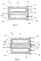
- FIG. 2 shows in detail an electrical energy source 14 according to a first embodiment of the implant described here.
- an electrically conductive, preferably hermetically sealed housing 24 which is made of metal, for example , two electrodes 26 and 28 are arranged.
- two electrodes 26 and 28 are arranged in an electrically conductive, preferably hermetically sealed housing 24, which is made of metal, for example .
- the implant does not matter which of the two electrodes 26 and 28 the anode and which is the cathode, is used in the present description for the sake of simplicity the electrode 26 is referred to as the anode and the electrode 28 as the cathode.
- the Interior of the housing 24 is filled with an electrolyte 30, the anode 26 and the cathode 28 are separated from one another by a diaphragm 32.
- the diaphragm 32 which can be, for example, a microporous plastic separator an electrical insulator, however, allows ion migration between the two electrodes 26 and 28.
- the mode 26 and the cathode 28 are opposite the electrically conductive Housing 24 electrically insulated, for example by means of one on the inside of the housing wall applied insulating layer 45.
- the anode 26 and the cathode 28 are further via lines 34 and 36, which pass through bushings 38 and 40 from the housing 24 are connected to the control unit 12, as shown in FIG. 1 is indicated.
- a tap 42 is provided on the housing 24, at which a reference potential is tapped can be.
- the tap 42 can be used as one Line 44 may be executed, which is conductively connected to the outside of the housing 24, for example is soldered to this, as shown in FIG. 2 is illustrated.
- Line 44 is the case potential-free, or a zero potential can be used on line 44 as a reference to that Anode potential and the cathode potential can be tapped.
- the electrical energy source 14 is an electrochemical primary cell
- any conventional electrode / electrolyte system can be used, such as Zn / AgO, Zn / MnO 2 , lithium-based cells, organic systems and those with liquid low or high viscosity electrolytes and solid electrolyte systems.
- the electrical energy source 14 is designed as an electrochemical secondary cell, metal / air accumulators such as, for example, zinc / air systems, Zn / MnO 2 systems, nickel-cadmium cells, nickel-metal hydride systems, or else lithium cells be used.
- Lithium cells are to be understood in the present case as cells in which a solid-state cathode made of intercalation compounds is used together with an anode made of metallic lithium in combination with a liquid, organic electrolyte or an electrolyte made of solid polymer, as well as lithium-ion cells with liquid or solid Polymer electrolytes, lithium alloy cells and the like.
- a polymer electrolyte is used as the electrolyte, which in addition to its function as Ion conductor also takes on a separator function at the same time, so you can refer to the in FIG. 2nd shown diaphragm 32 are dispensed with.
- Such polymer electrolytes can be in the form of real polymer electrolytes, or in the form of a microporous polymer, in the pores of which an electrolyte solution is introduced.
- the current-carrying electrodes 26 and 28 can be observed independently of one another by comparing the potentials on the lines 34 and 44 or 36 and 44.
- one inserted in the implant 10 electrochemical energy source 14 is electrical conductive housing 24 divided into two housing sections 46 and 48, which the in an electrolyte 30, separated by a diaphragm 32 Surround electrodes 26 and 28.
- There is an insulator between the housing sections 46 and 48 50 is provided, and on each of the housing sections 46 and 48 there is a tap 52 or 54 provided, on which the potential of the respective Housing section can be tapped to as a reference potential when evaluating the to provide electrical energy source.
- modified embodiment of an implant side electrochemical energy sources are instead of the diaphragm shown in FIG dividing the interior of the housing into two areas that receive the electrodes, the anode 26 and the cathode 28 each surrounded by a diaphragm 60 or 62, which indeed allows an ion migration from and to the anode or the cathode, but that one electrical insulator, i.e. prevents electron migration.
- the housing of the electrical energy source 14 which is like that in FIG. 3 housing shown divided into two housing sections 46 and 48 by a circumferential insulator 50 can be made of metal or another conductive material is used in this Design effectively a short circuit between the anode or the cathode and the Prevents housing.
- the embodiment of an electrochemical energy source according to FIG. 5 is equipped with three potential probes independent of the anode 26 and the cathode 28. Two of these potential probes are in turn formed by lines 56 and 58 attached to taps 52 and 54, by means of which the potentials of the housing sections 46 and 48 can be determined, while a third potential probe 64 is arranged in the electrolyte 30 between the two electrodes 26 and 28. If the housing 24 is an electrically conductive housing, then insulation must be provided between the third potential probe 64 and the housing, which according to FIG. 5 can be accomplished in that the third potential probe 64 is passed through the insulator 50. However, it goes without saying that the potential probe can also be passed through the housing 24 at any other point, provided that suitable insulation is provided.
- a passage through an electrically conductive housing can be produced, for example, by the component to be insulated, in particular the supply line of the potential probe or at least one of the lines leading to the electrodes 26, 28, being provided in an opening in the housing in Al 2 O 3 is shed.
- the component to be insulated in particular the supply line of the potential probe or at least one of the lines leading to the electrodes 26, 28, being provided in an opening in the housing in Al 2 O 3 is shed.
- two or more of these leads can also be combined in a common feedthrough.
- FIG. 6 shows an even further modified embodiment of an electrochemical energy source, as used in the implant 10 described here.
- the housing 24 is divided into three housing sections, a first surrounding the anode 26 Housing section 46, a second housing section surrounding the cathode 28 48 and a third arranged between the first and second housing sections Housing section 66.
- An insulator 50 is arranged between each housing section.
- the third housing section 66 is also provided with a tap 74, on which the potential of the third housing section is tapped via a line 76 can be.
- FIG. 6 an isolator 78 indicated in order to shield the potential probe 70 against the electrically conductive housing 24.
- Such an isolator is shown in FIG. 6 shown embodiment not really needed, since its function differs from that between the first and the third Housing section arranged insulating connector 50 is already met but necessary if the potential probe is used in a place where none such insulator is already integrated in the housing wall.
- Control measurements can be simple Measurements of potential differences between the reference electrode and an active electrode his. But also more complex measuring methods, e.g. (Cyclo) voltammetric studies with DC or combined DC / AC excitation signals as well as impedance spectroscopic measurements and generally all those familiar to the person skilled in the art electroanalytical methods that are useful for the respective investigation or testing, can with the described structure of the electrical provided in the implant Energy source carried out in combination with commercially available measuring equipment become. The time of such measurements is already during the production process to be scheduled.
- an electrical energy source for an implant to be used for the purpose of determining and monitoring the state of the energy source one or more potential measurements in addition to the detection of the individual
- electrode potentials are also possible with supercapacitors in particular with double layer capacitors, redox capacitors or Realize pseudo capacitors, as well as with fuel cells.
Landscapes
- Chemical & Material Sciences (AREA)
- Chemical Kinetics & Catalysis (AREA)
- Electrochemistry (AREA)
- General Chemical & Material Sciences (AREA)
- Engineering & Computer Science (AREA)
- Manufacturing & Machinery (AREA)
- Health & Medical Sciences (AREA)
- Nuclear Medicine, Radiotherapy & Molecular Imaging (AREA)
- Biomedical Technology (AREA)
- Radiology & Medical Imaging (AREA)
- Life Sciences & Earth Sciences (AREA)
- Animal Behavior & Ethology (AREA)
- General Health & Medical Sciences (AREA)
- Public Health (AREA)
- Veterinary Medicine (AREA)
- Prostheses (AREA)
- Electrotherapy Devices (AREA)
- Hybrid Cells (AREA)
Applications Claiming Priority (2)
| Application Number | Priority Date | Filing Date | Title |
|---|---|---|---|
| DE19837863 | 1998-08-20 | ||
| DE19837863A DE19837863C1 (de) | 1998-08-20 | 1998-08-20 | Implantat |
Publications (1)
| Publication Number | Publication Date |
|---|---|
| EP0981262A2 true EP0981262A2 (fr) | 2000-02-23 |
Family
ID=7878191
Family Applications (1)
| Application Number | Title | Priority Date | Filing Date |
|---|---|---|---|
| EP98121614A Withdrawn EP0981262A2 (fr) | 1998-08-20 | 1998-11-12 | Implant |
Country Status (5)
| Country | Link |
|---|---|
| US (1) | US6192272B1 (fr) |
| EP (1) | EP0981262A2 (fr) |
| AU (1) | AU747384B2 (fr) |
| CA (1) | CA2270689C (fr) |
| DE (1) | DE19837863C1 (fr) |
Cited By (3)
| Publication number | Priority date | Publication date | Assignee | Title |
|---|---|---|---|---|
| EP1073132A1 (fr) * | 1999-07-30 | 2001-01-31 | IMPLEX Aktiengesellschaft Hearing Technology | Pile électrochimique secondaire |
| CN102545310A (zh) * | 2011-11-29 | 2012-07-04 | 卢小平 | 水中电动玩具的供电方法及供电装置 |
| DE102017119818B4 (de) | 2016-08-31 | 2025-03-13 | GM Global Technology Operations LLC | Batteriezellensystem und batteriezellenüberwachungssystem |
Families Citing this family (17)
| Publication number | Priority date | Publication date | Assignee | Title |
|---|---|---|---|---|
| EP1304017B1 (fr) * | 2000-06-30 | 2015-12-02 | Cochlear Limited | Implant cochleaire |
| DE10041728A1 (de) | 2000-08-25 | 2002-03-21 | Implex Hear Tech Ag | Implantierbare medizinische Vorrichtung mit einem hermetisch dichten Gehäuse |
| DE10041727C2 (de) * | 2000-08-25 | 2003-04-10 | Cochlear Ltd | Implantierbares hermetisch dichtes Gehäuse für eine implantierbare medizinische Vorrichtung |
| US8123814B2 (en) | 2001-02-23 | 2012-02-28 | Biomet Manufacturing Corp. | Method and appartus for acetabular reconstruction |
| US7597715B2 (en) | 2005-04-21 | 2009-10-06 | Biomet Manufacturing Corp. | Method and apparatus for use of porous implants |
| DE10115429A1 (de) * | 2001-03-29 | 2002-05-02 | Siemens Audiologische Technik | Hörgerät |
| WO2003041209A2 (fr) * | 2001-11-01 | 2003-05-15 | Mir-Chem Gmbh | Dispositif et procede pour effectuer une mesure, a resolution spatiale et temporelle, d'un parametre de fonctionnement d'une cellule electrochimique |
| AU2003904086A0 (en) | 2003-08-04 | 2003-08-21 | Cochlear Limited | Implant battery short circuit protection |
| DE102005018128A1 (de) * | 2004-10-12 | 2006-04-13 | Restate Patent Ag | Elektromedizinisches Implantat |
| US8292967B2 (en) * | 2005-04-21 | 2012-10-23 | Biomet Manufacturing Corp. | Method and apparatus for use of porous implants |
| US8066778B2 (en) * | 2005-04-21 | 2011-11-29 | Biomet Manufacturing Corp. | Porous metal cup with cobalt bearing surface |
| US8021432B2 (en) | 2005-12-05 | 2011-09-20 | Biomet Manufacturing Corp. | Apparatus for use of porous implants |
| US8266780B2 (en) * | 2005-04-21 | 2012-09-18 | Biomet Manufacturing Corp. | Method and apparatus for use of porous implants |
| US7635447B2 (en) * | 2006-02-17 | 2009-12-22 | Biomet Manufacturing Corp. | Method and apparatus for forming porous metal implants |
| JP4384213B2 (ja) * | 2007-09-18 | 2009-12-16 | トヨタ自動車株式会社 | 二次電池の状態検出装置 |
| EP2205188B1 (fr) * | 2007-09-25 | 2014-04-09 | Biomet Manufacturing Corp. | Plateau tibial sans ciment |
| EP2828905A1 (fr) * | 2012-03-21 | 2015-01-28 | Li-Tec Battery GmbH | Cellule de conversion comprenant un boîtier de cellule, batterie comprenant au moins deux de ces cellules de conversion et procédé de fabrication d'une cellule de conversion |
Family Cites Families (4)
| Publication number | Priority date | Publication date | Assignee | Title |
|---|---|---|---|---|
| DE2622245A1 (de) * | 1976-05-19 | 1977-12-01 | Bbc Brown Boveri & Cie | Einrichtung zum bestimmen des entladezustandes einer elektrochemischen batterie |
| US4606350A (en) * | 1984-11-28 | 1986-08-19 | Telectronics N.V. | Pacemaker battery impedance test circuit and method of operation |
| US5817130A (en) * | 1996-05-03 | 1998-10-06 | Sulzer Intermedics Inc. | Implantable cardiac cardioverter/defibrillator with EMI suppression filter with independent ground connection |
| US6038473A (en) * | 1997-04-08 | 2000-03-14 | Survivalink Corporation | Defibrillator battery with dual cell stack configuration |
-
1998
- 1998-08-20 DE DE19837863A patent/DE19837863C1/de not_active Expired - Fee Related
- 1998-11-12 EP EP98121614A patent/EP0981262A2/fr not_active Withdrawn
-
1999
- 1999-04-29 CA CA002270689A patent/CA2270689C/fr not_active Expired - Fee Related
- 1999-04-30 AU AU26017/99A patent/AU747384B2/en not_active Ceased
- 1999-05-14 US US09/311,564 patent/US6192272B1/en not_active Expired - Lifetime
Cited By (5)
| Publication number | Priority date | Publication date | Assignee | Title |
|---|---|---|---|---|
| EP1073132A1 (fr) * | 1999-07-30 | 2001-01-31 | IMPLEX Aktiengesellschaft Hearing Technology | Pile électrochimique secondaire |
| US7232625B2 (en) | 1999-07-30 | 2007-06-19 | Cochlear Limited | Secondary electrochemical cell |
| US7713651B2 (en) | 1999-07-30 | 2010-05-11 | Cochlear Limited | Electrochemical cell |
| CN102545310A (zh) * | 2011-11-29 | 2012-07-04 | 卢小平 | 水中电动玩具的供电方法及供电装置 |
| DE102017119818B4 (de) | 2016-08-31 | 2025-03-13 | GM Global Technology Operations LLC | Batteriezellensystem und batteriezellenüberwachungssystem |
Also Published As
| Publication number | Publication date |
|---|---|
| US6192272B1 (en) | 2001-02-20 |
| DE19837863C1 (de) | 1999-10-28 |
| AU747384B2 (en) | 2002-05-16 |
| AU2601799A (en) | 2000-03-09 |
| CA2270689C (fr) | 2002-10-22 |
| CA2270689A1 (fr) | 2000-02-20 |
Similar Documents
| Publication | Publication Date | Title |
|---|---|---|
| DE19837863C1 (de) | Implantat | |
| DE69222567T2 (de) | Verfahren zur Messung der verbleibenden Ladung einer Speicherzelle | |
| DE102014217135B4 (de) | Verfahren und Vorrichtung zur Bestimmung eines State-of-Charge-Wertes einer Batterie | |
| DE3536111C2 (de) | Testvorrichtung und Testverfahren zum Feststellen der verbleibenden Lebensdauer einer Batterie | |
| DE102019125236A1 (de) | Batteriezelle mit einer Diagnoseeinheit, Verfahren zur Zustandsdiagnose einer Batteriezelle, Batterie sowie Kraftfahrzeug mit einer Batterie | |
| WO2015014764A2 (fr) | Module de stockage électrochimique et procédé permettant l'analyse d'une cellule de stockage électrochimique dans un module | |
| DE102016201026B4 (de) | Verfahren und Vorrichtung zur Bestimmung einer Restkapazität einer Blei-Säure-Batterie | |
| WO2020201009A1 (fr) | Électrode de référence en deux pièces | |
| DE102021108091A1 (de) | Charakterisieren und Laden eines lithiumbasierten elektrischen Energiespeichers abhängig von dessen Alterungszustand | |
| DE102017006334B3 (de) | Verfahren und Vorrichtung zur Feststellung und Vermeidung von degradationsförderlichen Prozessen während des Ladens von wiederaufladbaren Batteriezellen und deren Verwendung | |
| DE102022102499B4 (de) | Mess- und Überwachungsverfahren für eine Isolationseinrichtung sowie ein Batteriesystem | |
| DE102019200510A1 (de) | Messanordnung, Hochvoltbatterie, Kraftfahrzeug und Verfahren zum Bestimmen einer komplexen Impedanz | |
| DE102012018126A1 (de) | Vorrichtung und Verfahren zur Überwachung einer sekundären Lithium-lonen-Zelle und Lithium-lonen-Akkumulator | |
| DE102013226663A1 (de) | Fahrzeugbatterie mit Impedanzüberwachung | |
| DE102022110451A1 (de) | Verfahren und Vorrichtung zur Ermittlung der Impedanz eines wiederaufladbaren elektrischen Energiespeichers | |
| WO2011047908A1 (fr) | Source d'énergie pour courant électrique présentant un dispositif détecteur pour la détermination d'un état de charge de la source d'énergie | |
| DE102015226296A1 (de) | Akkumulatorzelle und Verfahren zum Herstellen und Betreiben einer Akkumulatorzelle | |
| EP4067890B1 (fr) | Détection de l'humidité dans un circuit électronique | |
| AT523526B1 (de) | Verfahren, Vorrichtung und System zur Bestimmung eines Kapazitätswertes einer Erdungskapazität eines ungeerdeten Stromnetzes | |
| DE2622245A1 (de) | Einrichtung zum bestimmen des entladezustandes einer elektrochemischen batterie | |
| DE102021132431A1 (de) | Batteriezellenmodul und Verfahren zur Bestimmung eines Ladezustands | |
| WO2003041209A2 (fr) | Dispositif et procede pour effectuer une mesure, a resolution spatiale et temporelle, d'un parametre de fonctionnement d'une cellule electrochimique | |
| DE102023213113B3 (de) | Vorrichtung und Verfahren zur Kapazitätsbestimmung von Hybrid-Kondensatorenergiespeichern in einem Hybrid-Kondensatorenergiespeicher und Schaltanlage mit einer solchen Kapazitätsbestimmung | |
| DE102019127910A1 (de) | Verfahren und vorrichtung zur überwachung einer elektrochemischen energiespeicherzelle sowie fahrzeug | |
| DE102015222051A1 (de) | Elektrodeneinheit für eine Batteriezelle und Verfahren zur Untersuchung einer Elektrodeneinheit |
Legal Events
| Date | Code | Title | Description |
|---|---|---|---|
| PUAI | Public reference made under article 153(3) epc to a published international application that has entered the european phase |
Free format text: ORIGINAL CODE: 0009012 |
|
| AK | Designated contracting states |
Kind code of ref document: A2 Designated state(s): AT BE CH CY DE DK ES FI FR GB GR IE IT LI LU MC NL PT SE |
|
| AX | Request for extension of the european patent |
Free format text: AL;LT;LV;MK;RO;SI |
|
| RAP1 | Party data changed (applicant data changed or rights of an application transferred) |
Owner name: IMPLEX AKTIENGESELLSCHAFT HEARING TECHNOLOGY |
|
| RAP1 | Party data changed (applicant data changed or rights of an application transferred) |
Owner name: COCHLEAR LIMITED |
|
| STAA | Information on the status of an ep patent application or granted ep patent |
Free format text: STATUS: THE APPLICATION HAS BEEN WITHDRAWN |
|
| 18W | Application withdrawn |
Effective date: 20041130 |