EP0981591B1 - Procede de production de combustible - Google Patents
Procede de production de combustible Download PDFInfo
- Publication number
- EP0981591B1 EP0981591B1 EP98916716A EP98916716A EP0981591B1 EP 0981591 B1 EP0981591 B1 EP 0981591B1 EP 98916716 A EP98916716 A EP 98916716A EP 98916716 A EP98916716 A EP 98916716A EP 0981591 B1 EP0981591 B1 EP 0981591B1
- Authority
- EP
- European Patent Office
- Prior art keywords
- fuel
- process according
- atmosphere
- chamber
- potential difference
- Prior art date
- Legal status (The legal status is an assumption and is not a legal conclusion. Google has not performed a legal analysis and makes no representation as to the accuracy of the status listed.)
- Expired - Lifetime
Links
- 239000000446 fuel Substances 0.000 title claims abstract description 148
- 238000000034 method Methods 0.000 title claims description 34
- 230000008569 process Effects 0.000 title claims description 34
- 238000004519 manufacturing process Methods 0.000 title description 3
- 239000003502 gasoline Substances 0.000 claims abstract description 56
- 239000004215 Carbon black (E152) Substances 0.000 claims abstract description 42
- 229930195733 hydrocarbon Natural products 0.000 claims abstract description 42
- 150000002430 hydrocarbons Chemical class 0.000 claims abstract description 42
- 239000012530 fluid Substances 0.000 claims description 31
- 239000007921 spray Substances 0.000 claims description 22
- 239000007788 liquid Substances 0.000 claims description 11
- XLYOFNOQVPJJNP-UHFFFAOYSA-N water Chemical compound O XLYOFNOQVPJJNP-UHFFFAOYSA-N 0.000 claims description 11
- 239000002245 particle Substances 0.000 claims description 10
- QSHDDOUJBYECFT-UHFFFAOYSA-N mercury Chemical compound [Hg] QSHDDOUJBYECFT-UHFFFAOYSA-N 0.000 claims description 6
- 229910052753 mercury Inorganic materials 0.000 claims description 6
- 230000008016 vaporization Effects 0.000 claims description 4
- MYMOFIZGZYHOMD-UHFFFAOYSA-N Dioxygen Chemical compound O=O MYMOFIZGZYHOMD-UHFFFAOYSA-N 0.000 claims 2
- 229910001882 dioxygen Inorganic materials 0.000 claims 2
- 238000002485 combustion reaction Methods 0.000 abstract description 13
- 230000005855 radiation Effects 0.000 abstract description 10
- -1 for example Substances 0.000 abstract description 6
- 239000003344 environmental pollutant Substances 0.000 abstract description 3
- 231100000719 pollutant Toxicity 0.000 abstract description 3
- YXFVVABEGXRONW-UHFFFAOYSA-N Toluene Chemical compound CC1=CC=CC=C1 YXFVVABEGXRONW-UHFFFAOYSA-N 0.000 description 21
- 239000000203 mixture Substances 0.000 description 19
- 150000002500 ions Chemical class 0.000 description 14
- 238000004458 analytical method Methods 0.000 description 13
- UHOVQNZJYSORNB-UHFFFAOYSA-N Benzene Chemical compound C1=CC=CC=C1 UHOVQNZJYSORNB-UHFFFAOYSA-N 0.000 description 12
- RYGMFSIKBFXOCR-UHFFFAOYSA-N Copper Chemical compound [Cu] RYGMFSIKBFXOCR-UHFFFAOYSA-N 0.000 description 8
- 150000001335 aliphatic alkanes Chemical class 0.000 description 8
- QVGXLLKOCUKJST-UHFFFAOYSA-N atomic oxygen Chemical compound [O] QVGXLLKOCUKJST-UHFFFAOYSA-N 0.000 description 8
- 230000015572 biosynthetic process Effects 0.000 description 8
- 229910052802 copper Inorganic materials 0.000 description 8
- 239000010949 copper Substances 0.000 description 8
- 239000007789 gas Substances 0.000 description 8
- 239000001301 oxygen Substances 0.000 description 8
- 229910052760 oxygen Inorganic materials 0.000 description 8
- 238000001228 spectrum Methods 0.000 description 8
- AFABGHUZZDYHJO-UHFFFAOYSA-N 2-Methylpentane Chemical compound CCCC(C)C AFABGHUZZDYHJO-UHFFFAOYSA-N 0.000 description 7
- 150000001875 compounds Chemical class 0.000 description 7
- 238000010438 heat treatment Methods 0.000 description 7
- 238000002347 injection Methods 0.000 description 7
- 239000007924 injection Substances 0.000 description 7
- BZLVMXJERCGZMT-UHFFFAOYSA-N Methyl tert-butyl ether Chemical compound COC(C)(C)C BZLVMXJERCGZMT-UHFFFAOYSA-N 0.000 description 6
- 150000001491 aromatic compounds Chemical class 0.000 description 5
- 238000006243 chemical reaction Methods 0.000 description 5
- FYGHSUNMUKGBRK-UHFFFAOYSA-N 1,2,3-trimethylbenzene Chemical compound CC1=CC=CC(C)=C1C FYGHSUNMUKGBRK-UHFFFAOYSA-N 0.000 description 4
- YNQLUTRBYVCPMQ-UHFFFAOYSA-N Ethylbenzene Chemical compound CCC1=CC=CC=C1 YNQLUTRBYVCPMQ-UHFFFAOYSA-N 0.000 description 4
- IMNFDUFMRHMDMM-UHFFFAOYSA-N N-Heptane Chemical compound CCCCCCC IMNFDUFMRHMDMM-UHFFFAOYSA-N 0.000 description 4
- CTQNGGLPUBDAKN-UHFFFAOYSA-N O-Xylene Chemical compound CC1=CC=CC=C1C CTQNGGLPUBDAKN-UHFFFAOYSA-N 0.000 description 4
- 239000006185 dispersion Substances 0.000 description 4
- 238000001819 mass spectrum Methods 0.000 description 4
- TVMXDCGIABBOFY-UHFFFAOYSA-N octane Chemical compound CCCCCCCC TVMXDCGIABBOFY-UHFFFAOYSA-N 0.000 description 4
- 238000003756 stirring Methods 0.000 description 4
- 239000008096 xylene Substances 0.000 description 4
- HYFLWBNQFMXCPA-UHFFFAOYSA-N 1-ethyl-2-methylbenzene Chemical compound CCC1=CC=CC=C1C HYFLWBNQFMXCPA-UHFFFAOYSA-N 0.000 description 3
- JMMZCWZIJXAGKW-UHFFFAOYSA-N 2-methylpent-2-ene Chemical compound CCC=C(C)C JMMZCWZIJXAGKW-UHFFFAOYSA-N 0.000 description 3
- 150000001336 alkenes Chemical class 0.000 description 3
- 229910002091 carbon monoxide Inorganic materials 0.000 description 3
- 238000001816 cooling Methods 0.000 description 3
- 238000002290 gas chromatography-mass spectrometry Methods 0.000 description 3
- 230000006872 improvement Effects 0.000 description 3
- 230000007246 mechanism Effects 0.000 description 3
- ODLMAHJVESYWTB-UHFFFAOYSA-N propylbenzene Chemical compound CCCC1=CC=CC=C1 ODLMAHJVESYWTB-UHFFFAOYSA-N 0.000 description 3
- 239000007858 starting material Substances 0.000 description 3
- 150000003738 xylenes Chemical class 0.000 description 3
- QUBBAXISAHIDNM-UHFFFAOYSA-N 1-ethyl-2,3-dimethylbenzene Chemical compound CCC1=CC=CC(C)=C1C QUBBAXISAHIDNM-UHFFFAOYSA-N 0.000 description 2
- JVSWJIKNEAIKJW-UHFFFAOYSA-N 2-Methylheptane Chemical compound CCCCCC(C)C JVSWJIKNEAIKJW-UHFFFAOYSA-N 0.000 description 2
- PFEOZHBOMNWTJB-UHFFFAOYSA-N 3-methylpentane Chemical compound CCC(C)CC PFEOZHBOMNWTJB-UHFFFAOYSA-N 0.000 description 2
- URLKBWYHVLBVBO-UHFFFAOYSA-N Para-Xylene Chemical group CC1=CC=C(C)C=C1 URLKBWYHVLBVBO-UHFFFAOYSA-N 0.000 description 2
- OFBQJSOFQDEBGM-UHFFFAOYSA-N Pentane Chemical compound CCCCC OFBQJSOFQDEBGM-UHFFFAOYSA-N 0.000 description 2
- ATUOYWHBWRKTHZ-UHFFFAOYSA-N Propane Chemical compound CCC ATUOYWHBWRKTHZ-UHFFFAOYSA-N 0.000 description 2
- 239000000654 additive Substances 0.000 description 2
- 239000000443 aerosol Substances 0.000 description 2
- 150000004945 aromatic hydrocarbons Chemical class 0.000 description 2
- 230000003197 catalytic effect Effects 0.000 description 2
- 230000005684 electric field Effects 0.000 description 2
- 230000005281 excited state Effects 0.000 description 2
- 239000002828 fuel tank Substances 0.000 description 2
- 230000008570 general process Effects 0.000 description 2
- NNPPMTNAJDCUHE-UHFFFAOYSA-N isobutane Chemical compound CC(C)C NNPPMTNAJDCUHE-UHFFFAOYSA-N 0.000 description 2
- IVSZLXZYQVIEFR-UHFFFAOYSA-N m-xylene Chemical group CC1=CC=CC(C)=C1 IVSZLXZYQVIEFR-UHFFFAOYSA-N 0.000 description 2
- VNWKTOKETHGBQD-UHFFFAOYSA-N methane Chemical compound C VNWKTOKETHGBQD-UHFFFAOYSA-N 0.000 description 2
- VLKZOEOYAKHREP-UHFFFAOYSA-N n-Hexane Chemical compound CCCCCC VLKZOEOYAKHREP-UHFFFAOYSA-N 0.000 description 2
- 210000002381 plasma Anatomy 0.000 description 2
- 230000009467 reduction Effects 0.000 description 2
- 238000000926 separation method Methods 0.000 description 2
- 239000000243 solution Substances 0.000 description 2
- 150000005199 trimethylbenzenes Chemical class 0.000 description 2
- 238000009834 vaporization Methods 0.000 description 2
- ZFFMLCVRJBZUDZ-UHFFFAOYSA-N 2,3-dimethylbutane Chemical compound CC(C)C(C)C ZFFMLCVRJBZUDZ-UHFFFAOYSA-N 0.000 description 1
- GXDHCNNESPLIKD-UHFFFAOYSA-N 2-methylhexane Natural products CCCCC(C)C GXDHCNNESPLIKD-UHFFFAOYSA-N 0.000 description 1
- AEXMKKGTQYQZCS-UHFFFAOYSA-N 3,3-dimethylpentane Chemical compound CCC(C)(C)CC AEXMKKGTQYQZCS-UHFFFAOYSA-N 0.000 description 1
- UGFAIRIUMAVXCW-UHFFFAOYSA-N Carbon monoxide Chemical compound [O+]#[C-] UGFAIRIUMAVXCW-UHFFFAOYSA-N 0.000 description 1
- UFHFLCQGNIYNRP-UHFFFAOYSA-N Hydrogen Chemical compound [H][H] UFHFLCQGNIYNRP-UHFFFAOYSA-N 0.000 description 1
- 208000027418 Wounds and injury Diseases 0.000 description 1
- 238000010521 absorption reaction Methods 0.000 description 1
- 150000001555 benzenes Chemical class 0.000 description 1
- 125000004432 carbon atom Chemical group C* 0.000 description 1
- 239000003054 catalyst Substances 0.000 description 1
- 230000008859 change Effects 0.000 description 1
- 230000001010 compromised effect Effects 0.000 description 1
- 238000009833 condensation Methods 0.000 description 1
- 230000005494 condensation Effects 0.000 description 1
- 239000004020 conductor Substances 0.000 description 1
- 230000006378 damage Effects 0.000 description 1
- 238000011157 data evaluation Methods 0.000 description 1
- 230000001934 delay Effects 0.000 description 1
- 230000001419 dependent effect Effects 0.000 description 1
- 239000003599 detergent Substances 0.000 description 1
- 239000002283 diesel fuel Substances 0.000 description 1
- WSSSPWUEQFSQQG-UHFFFAOYSA-N dimethylbutene Natural products CC(C)CC=C WSSSPWUEQFSQQG-UHFFFAOYSA-N 0.000 description 1
- 238000007599 discharging Methods 0.000 description 1
- 230000000694 effects Effects 0.000 description 1
- 238000010828 elution Methods 0.000 description 1
- 239000003995 emulsifying agent Substances 0.000 description 1
- 230000007613 environmental effect Effects 0.000 description 1
- 230000005284 excitation Effects 0.000 description 1
- 230000001747 exhibiting effect Effects 0.000 description 1
- 238000004880 explosion Methods 0.000 description 1
- 239000002360 explosive Substances 0.000 description 1
- 239000012634 fragment Substances 0.000 description 1
- 239000011521 glass Substances 0.000 description 1
- 230000036541 health Effects 0.000 description 1
- 238000005286 illumination Methods 0.000 description 1
- 208000014674 injury Diseases 0.000 description 1
- 238000007689 inspection Methods 0.000 description 1
- 239000001282 iso-butane Substances 0.000 description 1
- QWTDNUCVQCZILF-UHFFFAOYSA-N isopentane Chemical compound CCC(C)C QWTDNUCVQCZILF-UHFFFAOYSA-N 0.000 description 1
- 230000007774 longterm Effects 0.000 description 1
- 229910052751 metal Inorganic materials 0.000 description 1
- 239000002184 metal Substances 0.000 description 1
- 230000004048 modification Effects 0.000 description 1
- 238000012986 modification Methods 0.000 description 1
- IJDNQMDRQITEOD-UHFFFAOYSA-N n-butane Chemical compound CCCC IJDNQMDRQITEOD-UHFFFAOYSA-N 0.000 description 1
- 239000003345 natural gas Substances 0.000 description 1
- 229940078552 o-xylene Drugs 0.000 description 1
- 230000001590 oxidative effect Effects 0.000 description 1
- 239000001294 propane Substances 0.000 description 1
- 238000009877 rendering Methods 0.000 description 1
- 230000004044 response Effects 0.000 description 1
- 230000006903 response to temperature Effects 0.000 description 1
- 239000010802 sludge Substances 0.000 description 1
- 238000005507 spraying Methods 0.000 description 1
- 239000000758 substrate Substances 0.000 description 1
- 239000004094 surface-active agent Substances 0.000 description 1
- 230000004304 visual acuity Effects 0.000 description 1
Images


Classifications
-
- B—PERFORMING OPERATIONS; TRANSPORTING
- B01—PHYSICAL OR CHEMICAL PROCESSES OR APPARATUS IN GENERAL
- B01J—CHEMICAL OR PHYSICAL PROCESSES, e.g. CATALYSIS OR COLLOID CHEMISTRY; THEIR RELEVANT APPARATUS
- B01J19/00—Chemical, physical or physico-chemical processes in general; Their relevant apparatus
- B01J19/08—Processes employing the direct application of electric or wave energy, or particle radiation; Apparatus therefor
- B01J19/12—Processes employing the direct application of electric or wave energy, or particle radiation; Apparatus therefor employing electromagnetic waves
- B01J19/122—Incoherent waves
- B01J19/123—Ultraviolet light
-
- B—PERFORMING OPERATIONS; TRANSPORTING
- B01—PHYSICAL OR CHEMICAL PROCESSES OR APPARATUS IN GENERAL
- B01J—CHEMICAL OR PHYSICAL PROCESSES, e.g. CATALYSIS OR COLLOID CHEMISTRY; THEIR RELEVANT APPARATUS
- B01J19/00—Chemical, physical or physico-chemical processes in general; Their relevant apparatus
- B01J19/08—Processes employing the direct application of electric or wave energy, or particle radiation; Apparatus therefor
- B01J19/087—Processes employing the direct application of electric or wave energy, or particle radiation; Apparatus therefor employing electric or magnetic energy
- B01J19/088—Processes employing the direct application of electric or wave energy, or particle radiation; Apparatus therefor employing electric or magnetic energy giving rise to electric discharges
-
- B—PERFORMING OPERATIONS; TRANSPORTING
- B01—PHYSICAL OR CHEMICAL PROCESSES OR APPARATUS IN GENERAL
- B01J—CHEMICAL OR PHYSICAL PROCESSES, e.g. CATALYSIS OR COLLOID CHEMISTRY; THEIR RELEVANT APPARATUS
- B01J19/00—Chemical, physical or physico-chemical processes in general; Their relevant apparatus
- B01J19/08—Processes employing the direct application of electric or wave energy, or particle radiation; Apparatus therefor
- B01J19/12—Processes employing the direct application of electric or wave energy, or particle radiation; Apparatus therefor employing electromagnetic waves
- B01J19/122—Incoherent waves
- B01J19/126—Microwaves
-
- C—CHEMISTRY; METALLURGY
- C10—PETROLEUM, GAS OR COKE INDUSTRIES; TECHNICAL GASES CONTAINING CARBON MONOXIDE; FUELS; LUBRICANTS; PEAT
- C10G—CRACKING HYDROCARBON OILS; PRODUCTION OF LIQUID HYDROCARBON MIXTURES, e.g. BY DESTRUCTIVE HYDROGENATION, OLIGOMERISATION, POLYMERISATION; RECOVERY OF HYDROCARBON OILS FROM OIL-SHALE, OIL-SAND, OR GASES; REFINING MIXTURES MAINLY CONSISTING OF HYDROCARBONS; REFORMING OF NAPHTHA; MINERAL WAXES
- C10G32/00—Refining of hydrocarbon oils by electric or magnetic means, by irradiation, or by using microorganisms
-
- C—CHEMISTRY; METALLURGY
- C10—PETROLEUM, GAS OR COKE INDUSTRIES; TECHNICAL GASES CONTAINING CARBON MONOXIDE; FUELS; LUBRICANTS; PEAT
- C10G—CRACKING HYDROCARBON OILS; PRODUCTION OF LIQUID HYDROCARBON MIXTURES, e.g. BY DESTRUCTIVE HYDROGENATION, OLIGOMERISATION, POLYMERISATION; RECOVERY OF HYDROCARBON OILS FROM OIL-SHALE, OIL-SAND, OR GASES; REFINING MIXTURES MAINLY CONSISTING OF HYDROCARBONS; REFORMING OF NAPHTHA; MINERAL WAXES
- C10G32/00—Refining of hydrocarbon oils by electric or magnetic means, by irradiation, or by using microorganisms
- C10G32/02—Refining of hydrocarbon oils by electric or magnetic means, by irradiation, or by using microorganisms by electric or magnetic means
-
- B—PERFORMING OPERATIONS; TRANSPORTING
- B01—PHYSICAL OR CHEMICAL PROCESSES OR APPARATUS IN GENERAL
- B01J—CHEMICAL OR PHYSICAL PROCESSES, e.g. CATALYSIS OR COLLOID CHEMISTRY; THEIR RELEVANT APPARATUS
- B01J2219/00—Chemical, physical or physico-chemical processes in general; Their relevant apparatus
- B01J2219/08—Processes employing the direct application of electric or wave energy, or particle radiation; Apparatus therefor
- B01J2219/0803—Processes employing the direct application of electric or wave energy, or particle radiation; Apparatus therefor employing electric or magnetic energy
- B01J2219/0805—Processes employing the direct application of electric or wave energy, or particle radiation; Apparatus therefor employing electric or magnetic energy giving rise to electric discharges
- B01J2219/0807—Processes employing the direct application of electric or wave energy, or particle radiation; Apparatus therefor employing electric or magnetic energy giving rise to electric discharges involving electrodes
- B01J2219/0809—Processes employing the direct application of electric or wave energy, or particle radiation; Apparatus therefor employing electric or magnetic energy giving rise to electric discharges involving electrodes employing two or more electrodes
-
- B—PERFORMING OPERATIONS; TRANSPORTING
- B01—PHYSICAL OR CHEMICAL PROCESSES OR APPARATUS IN GENERAL
- B01J—CHEMICAL OR PHYSICAL PROCESSES, e.g. CATALYSIS OR COLLOID CHEMISTRY; THEIR RELEVANT APPARATUS
- B01J2219/00—Chemical, physical or physico-chemical processes in general; Their relevant apparatus
- B01J2219/08—Processes employing the direct application of electric or wave energy, or particle radiation; Apparatus therefor
- B01J2219/0803—Processes employing the direct application of electric or wave energy, or particle radiation; Apparatus therefor employing electric or magnetic energy
- B01J2219/0805—Processes employing the direct application of electric or wave energy, or particle radiation; Apparatus therefor employing electric or magnetic energy giving rise to electric discharges
- B01J2219/0807—Processes employing the direct application of electric or wave energy, or particle radiation; Apparatus therefor employing electric or magnetic energy giving rise to electric discharges involving electrodes
- B01J2219/0824—Details relating to the shape of the electrodes
- B01J2219/0835—Details relating to the shape of the electrodes substantially flat
-
- B—PERFORMING OPERATIONS; TRANSPORTING
- B01—PHYSICAL OR CHEMICAL PROCESSES OR APPARATUS IN GENERAL
- B01J—CHEMICAL OR PHYSICAL PROCESSES, e.g. CATALYSIS OR COLLOID CHEMISTRY; THEIR RELEVANT APPARATUS
- B01J2219/00—Chemical, physical or physico-chemical processes in general; Their relevant apparatus
- B01J2219/08—Processes employing the direct application of electric or wave energy, or particle radiation; Apparatus therefor
- B01J2219/0869—Feeding or evacuating the reactor
-
- B—PERFORMING OPERATIONS; TRANSPORTING
- B01—PHYSICAL OR CHEMICAL PROCESSES OR APPARATUS IN GENERAL
- B01J—CHEMICAL OR PHYSICAL PROCESSES, e.g. CATALYSIS OR COLLOID CHEMISTRY; THEIR RELEVANT APPARATUS
- B01J2219/00—Chemical, physical or physico-chemical processes in general; Their relevant apparatus
- B01J2219/08—Processes employing the direct application of electric or wave energy, or particle radiation; Apparatus therefor
- B01J2219/0873—Materials to be treated
- B01J2219/0877—Liquid
-
- B—PERFORMING OPERATIONS; TRANSPORTING
- B01—PHYSICAL OR CHEMICAL PROCESSES OR APPARATUS IN GENERAL
- B01J—CHEMICAL OR PHYSICAL PROCESSES, e.g. CATALYSIS OR COLLOID CHEMISTRY; THEIR RELEVANT APPARATUS
- B01J2219/00—Chemical, physical or physico-chemical processes in general; Their relevant apparatus
- B01J2219/08—Processes employing the direct application of electric or wave energy, or particle radiation; Apparatus therefor
- B01J2219/0894—Processes carried out in the presence of a plasma
-
- B—PERFORMING OPERATIONS; TRANSPORTING
- B01—PHYSICAL OR CHEMICAL PROCESSES OR APPARATUS IN GENERAL
- B01J—CHEMICAL OR PHYSICAL PROCESSES, e.g. CATALYSIS OR COLLOID CHEMISTRY; THEIR RELEVANT APPARATUS
- B01J2219/00—Chemical, physical or physico-chemical processes in general; Their relevant apparatus
- B01J2219/08—Processes employing the direct application of electric or wave energy, or particle radiation; Apparatus therefor
- B01J2219/12—Processes employing electromagnetic waves
- B01J2219/1203—Incoherent waves
- B01J2219/1206—Microwaves
- B01J2219/1209—Features relating to the reactor or vessel
- B01J2219/1212—Arrangements of the reactor or the reactors
- B01J2219/1215—Single reactor
-
- B—PERFORMING OPERATIONS; TRANSPORTING
- B01—PHYSICAL OR CHEMICAL PROCESSES OR APPARATUS IN GENERAL
- B01J—CHEMICAL OR PHYSICAL PROCESSES, e.g. CATALYSIS OR COLLOID CHEMISTRY; THEIR RELEVANT APPARATUS
- B01J2219/00—Chemical, physical or physico-chemical processes in general; Their relevant apparatus
- B01J2219/08—Processes employing the direct application of electric or wave energy, or particle radiation; Apparatus therefor
- B01J2219/12—Processes employing electromagnetic waves
- B01J2219/1203—Incoherent waves
- B01J2219/1206—Microwaves
- B01J2219/1209—Features relating to the reactor or vessel
- B01J2219/1221—Features relating to the reactor or vessel the reactor per se
- B01J2219/1239—Means for feeding and evacuation
Definitions
- This invention relates to a process for producing a highly combustible fuel.
- Automobiles employ a carburetor or a fuel injection which produces an explosive mixture of gasoline and air by spraying the gasoline into air.
- the mixture may be swirled through an intake manifold and delivered to the engine cylinders of an internal combustion engine; or the gasoline may be injected or inducted directly into the cylinders and the air may be delivered separately through the intake manifold. Whichever way the mixture is formed it is crude and unstable and if not combusted immediately droplets of liquid gasoline fall from the mixture.
- Aromatic hydrocarbons are included in gasoline to slow the combustion process and reduce knocking in the cylinders.
- This invention seeks to provide a highly combustible fuel for motor driven vehicles, more efficient and exhibiting lower levels of exhaust pollutants than conventional mixtures of gasoline and air.
- a process of producing combustible fuel comprising exposing an atmosphere of gaseous hydrocarbon fuel in the presence of an oxygeneous fluid, and maintained under vacuum, to a negative voltage direct current potential difference to produce negatively charged particles of combustible fuel, having improved combustibility as compared with said hydrocarbon fuel, said potential difference being applied under non-arcing conditions.
- the exposure is at an elevated temperature with the charged particles being fed to the engine cylinder.
- a gaseous hydrocarbon fuel is exposed to an electrical field or plasma, more especially an electrical ionization potential difference, or to ultraviolet radiation, microwave radiation or laser.
- the exposure is carried out in the presence of a gaseous carrier fluid, notably an oxygeneous fluid such as oxygen and/or air, or a mixture of oxygen and/or air and steam or gaseous water vapor.
- a gaseous carrier fluid notably an oxygeneous fluid such as oxygen and/or air, or a mixture of oxygen and/or air and steam or gaseous water vapor.
- the electrical ionization potential difference, or the radiation activates the gaseous hydrocarbon fuel to a high energy state, more especially the hydrocarbon molecules or ions of the fuel are thought to be electronically excited to a state in which they are more reactive or more susceptible to combustion than the hydrocarbon fuel in the non-excited state.
- the process generates an extremely finely divided aerosol having a particle size far smaller than that achieved with a normal carburetor or fuel injector equipped system.
- the droplet particles are initially formed in a strongly electrically-charged condition. This is a metastable condition, leading immediately to the disruption of the highly charged droplets by internal coulombic repulsion and the formation of much more finely divided droplets each of which carries a portion of the charge initially held by the original droplet.
- These second generation droplets may then rapidly and similarly undergo further disruption and dispersion and so on until the fuel - air mixture enters the combustion chambers and is ignited. Mutual electrostatic repulsion between these fuel particles prevents them from coalescing back to larger droplets.
- the droplets enter the combustion chambers relatively more finely divided than in a normal carburetor or fuel injector equipped system. Since burning of the fuel in the combustion chambers occurs at the fuel particle surface, its rate is therefore dependent upon the surface area. Burning at high engine speeds is incomplete before normally-sized droplets in the normal carburetor or fuel injector equipped systems are ejected as exhaust, and therefore completeness of combustion is compromised if the droplet size is large. On the other hand, an extremely finely divided dispersion provides a huge increase in the surface area for burning and leads to much more complete combustion with the resulting decrease in carbon monoxide and unburnt hydrocarbon emissions which are observed with this invention.
- a reactor employed in the invention was modified to incorporate a very fine mesh screen in the out flow stream of the reactor; the screen was insulated from the reactor components but electrically connected to an external detector of electrical current. In operation electrical charging of the screen was detected and it is likely that this results from partial collection and discharging of the charged droplets.
- the presence of the charge on the droplets of the aerosol likely enhances the ease with which the fuel dispersion is combusted, especially when the droplets are negatively charged, since the negatively charged droplets would have an increased affinity, for oxygen adduction.
- this excited state or charged droplets of the hydrocarbon molecules or ions may become bound to the gaseous carrier fluid, especially when the carrier fluid is an oxygeneous fluid, such as by forming an adduct between the oxygeneous fluid and the charged droplets.
- the chamber housing the gaseous hydrocarbon fuel may include a window transparent to the radiation or laser beam whereby the radiation or beam may be directed to the atmosphere of the gaseous hydrocarbon fuel.
- a gaseous, oxygeneous fluid is introduced into an atmosphere of gaseous hydrocarbon fuel maintained under vacuum.
- the gaseous, oxygeneous fluid is suitably oxygen and/or air, or a mixture of oxygen and/or air and steam or gaseous water vapor.
- the hydrocarbon fuel is suitably gasoline by which is to be understood the various grades of gasoline motor fuel; hydrocarbon fuel may also be diesel oil, natural gas or propane.
- the atmosphere of gaseous hydrocarbon fuel is formed by vaporizing a liquid hydrocarbon fuel, for example, gasoline, under vacuum or a slight pressure in a chamber.
- a vacuum facilitates formation of the gaseous atmosphere from the liquid hydrocarbon fuel.
- the vacuum corresponds to a negative pressure of 0.1 to 0.95 bar (3 to 28 inches of mercury), preferably 0.34 to 0.95 bar (10 to 28 inches of mercury); when the vaporization is carried out at a slight pressure this is suitably 1.03 to 1.1 bar (15 to 16 psi) and the atmosphere is formed at a temperature, relative to the pressure, of up to but not to exceed the fuel flash point.
- Test temperature can be increased up to the flash point of hydrocarbon fuel, but not exceeding it or explosion of said fuel can occur, resulting in personal injury to the experimenter.
- the vaporization is carried out at an elevated temperature, which conveniently is (250°F to 450°F) 121°C to 232°C, more especially (350°F to 410°F) 177°C to 210°C.
- the pressure extending from vacuum through partial vacuum to a slight positive pressure may be considered to be 0 - 1.1 bar (0 - 16 psi).
- the gaseous, oxygeneous fluid is conveniently introduced continuously into the hot atmosphere in the chamber, and the formed combustible fuel is continuously withdrawn from the chamber and delivered to the cylinders of an internal combustion engine, preferably within 5 minutes of its formation and more preferably within milliseconds of formation.
- the electrical ionization potential established across the atmosphere of the hydrocarbon fuel containing the oxygeneous fluid is suitably 200-8000 volts, more usually 600-5000 volts. This is achieved by a pair of spaced apart electrodes disposed so as to be within the aforementioned atmosphere. The spacing of the electrodes is such that any current flow resulting from the potential difference applied across the electrodes is minimal, typically of the order of 0.2 to 0.8 microamps. An average of 0.5 microamps was measured in the test set-up described herein. It should be noted that electrode area and configuration will affect the current flow. Arcing must not occur between electrodes or against any part of the set-up.
- one electrode is disposed within the reactor and the other electrode may be defined by the wall of the reactor.
- the hydrocarbon fuel is sprayed into a chamber from a spray nozzle and the oxygeneous fluid is introduced separately into the chamber, and a potential difference is established between the spray nozzle and a wall of the chamber particularly so as to produce negatively charged fuel droplets.
- the spray nozzle functions as an electrode.
- the potential difference is established between an electrode extending into the chamber and a wall of the chamber.
- the spray nozzle directs the hydrocarbon fuel generally axially of the chamber from the spray nozzle towards a fuel outlet of the chamber.
- the electrode extends axially of the chamber with an inner end in spaced opposed relationship with the spray nozzle such that the gaseous hydrocarbon fuel flows axially of the chamber along and about the electrode towards the fuel outlet.
- the electrode extends inwardly of a wall of the chamber and substantially normal to the axial flow of gaseous hydrocarbon fuel from the spray nozzle to the fuel outlet.
- the air and the gaseous hydrocarbon fuel are suitably employed in a volume ratio of air to gaseous hydrocarbon fuel of 10 to 30:1, preferably 12 to 17:1.
- the combustible fuel may be fed directly to the cylinders of an internal combustion engine, no carburetor, choke or injection system is employed.
- a condensate of the combustible fuel may also be formed, by subjecting the fuel to condensing conditions such as by cooling.
- the combustible fuel in gaseous form does not require long term stability as it is normally formed as required and is burned continuously as it is produced, usually within a few milliseconds.
- the gaseous combustible fuel reverts to a liquid after about 10 minutes.
- Formation of the combustible fuel can be observed as a cloud which is a whitish, silvery grey in color, while the gaseous gasoline is colourless.
- the combustible fluid has been observed to retain the configuration of the bore of the conduit as it emerges from an end of the conduit and to retain this configuration as the fuel advances from the conduit, and then expand to a cloud.
- a vacuum was applied to draw the cloud back into the conduit, the cloud shrank to the configuration that it had, when it first emerged from the conduit and the last of it was then drawn into the conduit.
- condensation of the combustible fuel does not result in separation of water and gasoline, as would be expected in the case of a mere mixture.
- the combustible fuel in condensed form is homogeneous and stable. This combustible fuel is, of course, formed without emulsifiers, surfactants, catalysts or other additives.
- the steam derived liquid fuel condensate is relatively stable for several days and a test tube sample absorbed two more drops of water into solution readily without any evidence of separation. A third droplet of water was rejected from absorption into the solution and fell directly to the bottom of the test tube. This response being the same as adding a droplet of water directly to gasoline or oil.
- the formation of the combustible fuel is visible, the cloud of combustible fuel formed about the electrodes being different from the surrounding atmosphere.
- gaseous fuel produced in accordance with the invention may be employed directly as produced or a condensate of the gaseous fuel may be produced, which liquid condensate may be employed as a substrate for conventional fuels such as gasoline.
- These two classes of condensate differ both in composition and combustion characteristics.
- condensates of these two classes may be blended together to provide desired characteristics for particular applications, for example, for automobiles or jet engines or furnaces or boilers.
- these condensates may be blended with conventional fuels, for example, gasoline, to provide a blend of desired characteristics.
- conventional gasoline may produce a fuel in which the pollution generated during combustion is reduced in an amount proportionate to the content of the new condensate or condensates in the blend, as compared with that produced by the gasoline alone.
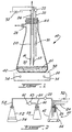
- a laboratory assembly 10 includes a flask 12, a heat and stir unit 14 and electrodes 16 and 18.
- An inlet line 20 having a valve 22 is connected to a source of oxygeneous fluid such as air.
- An outlet line 24 connects the interior of flask 12 to a site requiring the combustible fuel to drive a motor.
- Flask 12 has a port 26 which in use is connected to a vacuum pump (not shown) or to a motor intake manifold port effective to establish a vacuum within flask 12.
- Electrodes 16 and 18 are in spaced apart relationship and are connected by electrical conductors 28 and 30, respectively to an electrical power source 32 effective to provide a potential difference between electrodes 16 and 18.
- Heat and stir unit 14 includes temperature and stir controls 34 and 36 respectively.
- Unit 14 houses a heating unit (not shown) which in response to temperature control 34 heats a top surface 38 thereby heating a liquid hydrocarbon fuel 40 such as gasoline, housed in flask 12.
- Stir control 36 activates a stirrer 42 located within the fuel 40 in flask 12. Movement of stirrer 42 to agitate fuel 40 may, for example, be by magnet control.
- Flask 12 is closed by closure 44.
- FIG. 2 With further reference to Fig. 2 there is shown a modification of Fig. 1 in which assembly 10 is supplemented by a flask 52 supported by a heating unit 54; and a flask 56.
- Flask 56 has an air inlet line 62.
- the production of the combustible fuel proceeds as follows.
- Flask 12 is placed under vacuum and the liquid gasoline 40 in flask 12 is heated and agitated by unit 14 to develop a gasoline atmosphere 70 around electrodes 16 and 18.
- An oxygeneous fluid for example, air is introduced into the atmosphere 70 through line 20 and a potential difference is established between electrodes 16 and 18 by electrical power source 32. A change in the appearance of atmosphere 70 is visible to the naked eye.
- atmosphere 70 is continuously developed and oxygeneous fluid air is continuously introduced, the combustible fuel developed from atmosphere 70 and the oxygeneous fluid is continuously withdrawn from flask 12 through line 24 and is dispatched directly to provide power to a motor.
- the oxygeneous fluid fed through line 22 is a mix of air and steam.
- Steam is developed from water in flask 52 by the heating unit 54 and passes from flask 52 through line 58.
- Air is drawn into flask 56 through line 62, having metering valve 63 therein and then passes from flask 56 through line 60 which meets line 58 at line 20.
- Flask 56 also serves as a trap for condensed water from the steam in line 58, which condensed water flows through line 60 in opposition to the flow of air.
- the mixture of steam and air is delivered through line 20 into flask 56 where the combustible fuel is developed around the electrodes 16 and 18 in the same manner as described for the embodiment of Fig. 1.
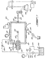
- a reactor assembly 100 comprises a reactor 102, a fuel supply 104 and a fuel line 106 to a motor shown generally at 108.
- Reactor 102 comprises a housing 110, a fuel delivery pipe 112 which terminates in a spray nozzle 114 is mounted in an electrically insulating sleeve 116 in a port 118 in housing 110.
- Housing 102 has an air inlet port 120 and a fuel outlet port 122.
- a heating element 124 surrounds housing 110 and a voltage source 126 is connected between a wall 128 of housing 110 and pipe 112 such that pipe 112 and wall 128 form spaced apart electrodes across which a continuous ionizing direct current potential difference is established.
- a vacuum gauge 130 monitors the vacuum in housing 110 and a thermocouple meter 132 monitors the temperature of reactor 102 established by heating element 124.
- Feed line 134 feeds air or oxygen to housing 110, the flow being controlled by a metering valve 136.
- Fuel supply 104 includes a fuel tank 138 and a fuel line 140 communicating with fuel delivery pipe 112. Fuel pump 142 and pressure gauge 144 are disposed in fuel line 140. A fuel by-pass line 146 having a metering valve 148 returns fuel in line 140 to tank 138.
- Fuel line 106 includes an outflow line 150 from fuel outlet port 122, a cooling tower 152, a condensate collector 154, a vacuum control and manifold 156 and a vacuum pump 158.
- Reactor 102 further includes a drain line 160 having a valve shut off 162.
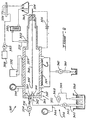
- FIG. 8 there is shown an assembly 200 having a reactor 202.
- Reactor 202 has a housing 210 and a spray nozzle 214 at the end of a delivery pipe 212 in an end wall 264 of housing 210.
- An electrode 266 is mounted in an electrically insulating sleeve 268 extending through wall 228.
- Other components of assembly 200 which correspond to those of assembly 100 in Fig. 7 have the same identifying integers increased by 100. In this case, a continuous ionizing direct current potential difference is established by voltage source 226 between electrode 266 and wall 228.
- FIG. 9 there is shown an assembly 300 having a reactor 302.
- Reactor 302 has a housing 310 and a spray nozzle 314 at the end of a delivery pipe 312 in an end wall 364 of housing 310.
- An elongate metal rod 366 extends within housing 310 being mounted in an electrically insulating sleeve 368 in wall 328 of housing 310.
- An inner end 370 of rod 366 is in spaced apart relationship with spray nozzle 314 so that fuel sprayed into housing 310 from spray nozzle 314 flows about rod 366.
- Voltage source 326 is connected between rod 366 and housing wall 328. In this case a continuous ionizing direct current potential difference is established by voltage source 326 between rod 366 and wall 328.
- Other components of assembly 300 which correspond to those of assembly 100 in Fig. 7 have the same identifying integers increased by 200.
- fuel is pumped from fuel tank 138 and fuel line 140 to fuel delivery pipe 112, 212 or 312 and the fuel is delivered as a spray from spray nozzle 114, 214 or 314 into the interior of housing 110, 210 or 310.
- a d.c. high voltage potential difference typically about 3,000 volts is established by voltage source 126, 226 or 326, and heating element 124, 224 or 324 establishes an elevated temperature typically about (400°F) 204°C within housing 110, 210 or 310.
- Air is introduced into housing 110, 210 or 310 from line 134.
- the high voltage potential difference and elevated temperature produce a fine dispersion of charged fuel droplets in housing 110, 210 or 310 which charged fuel droplets together with the air introduced by line 134 is drawn from housing 110, 210 or 310 by vacuum pump 158 to motor 108, via fuel outlet port 122, 222 or 322, cooling tower 152, condensate collector 154 and vacuum control and manifold 156.
- a combustible fuel was developed employing the assembly 10 of Fig. 1 using air as the oxygeneous fluid and gasoline (92 octane) as the hydrocarbon fuel at an air to gaseous gasoline volume ratio of 33:1, under a vacuum of 0.61 bar (18 inches of mercury).
- the potential difference between the electrodes 16 and 18 was 700 volts d.c.
- the gasoline vapor atmosphere was developed at a temperature of 121°C (250°F).
- the resulting combustible fuel was dispatched directly to the motor cylinders to fuel a gasoline-powered truck motor having a V-8 engine, and was combusted within 10 milliseconds of being developed.
- the motor was operated at 1235 rpm.
- the exhaust was analyzed.
- the motor started easily without choke, ran very smoothly, did not stall or back fire and operated without a catalytic converter, anti-pollution device, carburetor or fuel injection system.
- a combustible fuel was developed employing the assembly 10 of Fig. 1 using air as the oxygeneous fuel and gasoline (92 octane) as the hydrocarbon fuel at an air to gaseous volume ratio of 16:1, under a vacuum of 0.7 bar (2 inches of mercury).
- the potential difference between the electrodes 16 and 18 was 800 volts.
- the gasoline vapor atmosphere was developed at a temperature of 79°C (174°F).
- the resulting combustible fuel was dispatched directly to fuel a 4-cylinder automobile (a 1982 Toyota).
- the motor of the automobile was operated at 900 rpm.
- the exhaust was analyzed.
- gasoline 92 octane
- the exhaust was analyzed.
- Gasoline is a complex mixture of isomeric alkanes having from 4 to 10 carbon atoms and aromatic compounds ranging from benzene, toluene and the three xylene isomers to higher alkylated benzenes. It also contains additives such as tertiary-butyl methyl ether (TBME) to increase effective octane rating and detergents meant to prevent fouling of carburetor and injector jets and to prevent oxidative formation of sludge with storage.
- TBME tertiary-butyl methyl ether
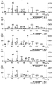
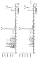
- E6614A shows ions characteristic of alkanes (m/z 29 (C 2 H 5 ), 43 (C 3 H 7 ), 57 etc.: the alkane series, each member increasing by an additional CH 2 , 14 mass units or Daltons (Da)).
- alkane series each member increasing by an additional CH 2 , 14 mass units or Daltons (Da)).
- alkene-derived ions with masses of 27, 41, 55, again increasing by 14 Da.
- the latter series are formed from the first by ejection of a hydrogen molecule (i.e. 29>27 + H 2 , 43>41 + H 2 , etc.).
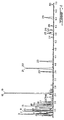
- Z0004 (Fig. 4) is the result of the GC-MS analysis of the starting gasoline. Thirty numbered peaks are identified by comparison of their mass spectra with authentic spectra for these compounds published in the US Environmental Protection Agency/National Institutes of Health Mass Spectra Data Base. For example, peak #7 is TBME and is not well resolved from peak #8, 2-methylpentane. The spectrum for peak 8 has a moderate intensity at 73 Da due to partial co-elution of TBME with 2-methylpentane. Inspection of the mass spectra scanned from Fig. 4 reveals the ions found in E6614A, Fig. 3, the aggregate spectrum obtained for the sample as a whole. In effect, then Fig. 3 could be considered to be the algebraic sum of all the spectra scanned for the 30 peaks of Fig. 4.
- UV radiation ultraviolet irradiation
- reactor 102 was modified to include within housing 110, a copper screen extending between an insulating ring mounted in the walls of housing 110 downstream of spray nozzle 114 and a volt meter was connected between the copper screen and the wall 128 of housing 110.
- the volt meter was employed to determine repeated charge on the copper screen during operation of the reactor 102 and during non-operation of the reactor 102 when the flow of fuel from tank 138 was discontinued.
- the charge on the copper screen as determined by the volt meter ranged from 10.15 mV to 11.4 mV in the repeated test results, while during non-operation of reactor 102 the volt meter readings ranged from -0.01 mV to -0.62 mV.
- the voltage source 12 applied a potential difference of -6110 volts and the housing 110 was maintained at (307°F to 312°F) 153°C to 155°C.
- the Table below shows the voltage on the copper screen with the reactor in operation and non-operating at different temperature and with some variation in the voltage applied by voltage source 226.
- Temperature (in 210) Applied voltage (226) HV ⁇ A Charge on screen Reactor condition 132°C (270°F) OV 0.1 ⁇ A +0.2 mV OFF 170°C (338°F) 5000V 0.1 ⁇ A -670.0 mV ON 170°C (338°F) 5000V 0.1 ⁇ A -2.0 mV OFF 171°C (340°F) 6000V 0.1 ⁇ A -870.0 mV ON 171°C (340°F) 6000V 0.1 ⁇ A -4.0 mV OFF 203°C (398°F) 6000V 0.1 ⁇ A -1.460.0 mV ON
- the spray nozzle 214 is positive as is wall 228 of the reactor and the electrode 266 is negative, and negative voltages are obtained on the copper screen (except where there is no applied voltage).
Landscapes
- Chemical & Material Sciences (AREA)
- Chemical Kinetics & Catalysis (AREA)
- Organic Chemistry (AREA)
- Oil, Petroleum & Natural Gas (AREA)
- Toxicology (AREA)
- General Health & Medical Sciences (AREA)
- Health & Medical Sciences (AREA)
- Engineering & Computer Science (AREA)
- Microbiology (AREA)
- General Chemical & Material Sciences (AREA)
- Life Sciences & Earth Sciences (AREA)
- Physics & Mathematics (AREA)
- Electromagnetism (AREA)
- Production Of Liquid Hydrocarbon Mixture For Refining Petroleum (AREA)
- Feeding And Controlling Fuel (AREA)
- Exhaust Gas After Treatment (AREA)
- Output Control And Ontrol Of Special Type Engine (AREA)
- Physical Or Chemical Processes And Apparatus (AREA)
Claims (24)
- Procédé de production de combustible comprenant l'exposition d'une atmosphère de combustible hydrocarboné gazeux en présence d'un fluide oxygéné, et maintenue sous vide, à une différence de potentiel continue négative pour produire des particules chargées négativement de combustible ayant une combustibilité améliorée comparativement au combustible hydrocarboné, la différence de potentiel étant appliquée dans des conditions de non-formation d'arc.
- Procédé selon la revendication 1, dans lequel la différence de potentiel est appliquée à ladite atmosphère entre une première et une deuxième électrodes, ces électrodes étant espacées de façon que le courant circulant entre celles-ci soit de 0,2 à 0,8 microampère.
- Procédé selon la revendication 2, dans lequel ladite atmosphère est contenue dans un réacteur et une des première et deuxième électrodes est formée par une paroi de ce réacteur.
- Procédé selon l'une des revendications 1, 2 et 3, dans lequel ledit combustible est de l'essence et le fluide oxygéné comprend de l'oxygène gazeux.
- Procédé selon la revendication 4, dans lequel ledit fluide est de l'air.
- Procédé selon la revendication 4, dans lequel ledit fluide comprend au moins un de l'oxygène gazeux et de l'air et au moins une de la vapeur d'eau et de la vapeur.
- Procédé selon l'une des revendications 1, 2, 3, 4, 5 et 6, dans lequel ledit combustible de combustibilité améliorée comprend ledit fluide oxygéné fixé audit combustible hydrocarboné gazeux.
- Procédé selon l'une des revendications 1 à 7, dans lequel ladite atmosphère est exposée à ladite différence de potentiel à une température élevée ne dépassant pas le point d'éclair du combustible hydrocarboné pour produire lesdites particules chargées négativement.
- Procédé selon la revendication 8, dans lequel la température élevée est de 177 à 210 °C (350 à 410 °F).
- Procédé selon la revendication 9, dans lequel ladite différence de potentiel et de 200 à 8000 volts et ladite exposition est faite sous un vide de 0,10 à 0,95 bar (3 à 28 pouces de mercure).
- Procédé selon la revendication 9, dans lequel ladite différence de potentiel est de 600 à 5000 volts et ladite exposition est faite à une pression de 0 à 1,1 bar (0 à 16 livres par pouce carré).
- Procédé selon l'une des revendications 1 à 11, comprenant :a) l'introduction d'un fluide gazeux oxygéné dans une atmosphère dudit combustible hydrocarboné gazeux maintenue sous vide, etb) l'établissement de ladite différence de potentiel continue négative à ladite atmosphère pour produire lesdites particules chargées négativement de combustible.
- Procédé selon la revendication 12, comprenant la vaporisation sous vide dans une chambre d'un combustible hydrocarboné liquide pour former ladite atmosphère dans la chambre, et dans lequel l'opération a) comprend l'introduction dudit fluide dans ladite atmosphère en un écoulement continu, et comportant l'opération dec) retrait continu dudit combustible de la chambre.
- Procédé selon la revendication 1, dans lequel ledit vide est de 0,1 à 0,95 bar (3 à 28 pouces de mercure) et ladite atmosphère est formée à une température élevée ne dépassant par le point d'éclair dudit combustible hydrocarboné gazeux.
- Procédé selon la revendication 14, dans lequel ladite température élevée est de 121 à 232 °C (250 à 450 °F).
- Procédé selon l'une des revendications 14 et 15, dans lequel ladite différence de potentiel et de 200 à 8000 volts.
- Procédé selon la revendication 13, dans lequel le combustible hydrocarboné gazeux est pulvérisé dans la chambre par une buse de pulvérisation, ladite différence de potentiel étant établie entre cette buse de pulvérisation et une paroi de la chambre.
- Procédé selon la revendication 13, dans lequel le combustible hydrocarboné gazeux est pulvérisé dans la chambre par une buse de pulvérisation et la différence de potentiel est établie entre une électrode entrant dans la chambre et une paroi de la chambre.
- Procédé selon la revendication 18, dans lequel l'électrode s'étend axialement par rapport à la chambre avec une extrémité intérieure en relation espacée opposée avec la buse de pulvérisation de façon que le combustible hydrocarboné gazeux s'écoule axialement par rapport à la chambre le long et autour de l'électrode vers une sortie de combustible de la chambre.
- Procédé selon la revendication 18, dans lequel l'électrode s'étend en dedans d'une paroi de la chambre et sensiblement normalement à un courant axial de combustible hydrocarboné gazeux de la buse de pulvérisation à une sortie de combustible de la chambre.
- Procédé selon la revendication 5, dans lequel l'air et l'essence sont présents dans ladite atmosphère dans un rapport en volume air/essence de 12 à 17.
- Procédé de production d'un combustible selon la revendication 1, dans lequel l'exposition est effectuée à une pression de 0 à 1,1 bar (0 à 16 livres par pouce carré).
- Procédé selon la revendication 1, dans lequel ladite atmosphère est à une température de 121 à 232 °C (250 à 450 °F).
- Procédé selon la revendication 1, dans lequel la différence de potentiel est appliquée à ladite atmosphère entre une première et une deuxième électrodes, ces électrodes étant espacées de façon que le courant circulant entre celles-ci soit de 0,1 microampère.
Applications Claiming Priority (5)
| Application Number | Priority Date | Filing Date | Title |
|---|---|---|---|
| US4406297P | 1997-04-17 | 1997-04-17 | |
| US44062P | 1997-04-17 | ||
| US5749197P | 1997-09-04 | 1997-09-04 | |
| US57491P | 1997-09-04 | ||
| PCT/CA1998/000367 WO1998047982A1 (fr) | 1997-04-17 | 1998-04-16 | Combustible et procede de production de combustible |
Publications (2)
| Publication Number | Publication Date |
|---|---|
| EP0981591A1 EP0981591A1 (fr) | 2000-03-01 |
| EP0981591B1 true EP0981591B1 (fr) | 2002-06-12 |
Family
ID=26721133
Family Applications (1)
| Application Number | Title | Priority Date | Filing Date |
|---|---|---|---|
| EP98916716A Expired - Lifetime EP0981591B1 (fr) | 1997-04-17 | 1998-04-16 | Procede de production de combustible |
Country Status (11)
| Country | Link |
|---|---|
| US (2) | US6193851B1 (fr) |
| EP (1) | EP0981591B1 (fr) |
| JP (1) | JP2001520700A (fr) |
| KR (1) | KR20010006555A (fr) |
| CN (1) | CN1175088C (fr) |
| AT (1) | ATE219131T1 (fr) |
| AU (1) | AU739594B2 (fr) |
| BR (1) | BR9809098A (fr) |
| CA (1) | CA2286589C (fr) |
| DE (1) | DE69806002T2 (fr) |
| WO (1) | WO1998047982A1 (fr) |
Families Citing this family (16)
| Publication number | Priority date | Publication date | Assignee | Title |
|---|---|---|---|---|
| EP0981591B1 (fr) * | 1997-04-17 | 2002-06-12 | Marc Jean Campagna | Procede de production de combustible |
| ATE245764T1 (de) | 1998-10-28 | 2003-08-15 | Terralogix 3227928 Canada Inc | Brennsystemreinigungsvorrichtung und katalytische umsetzungsvorrichtung |
| RU2158748C1 (ru) | 1999-10-20 | 2000-11-10 | Гандельман Леонид Яковлевич | Способ модификации моторного топлива и устройство для его осуществления |
| US8012435B2 (en) * | 1999-12-30 | 2011-09-06 | Thomas Merritt | Natural gas production utilizing a gas dynamic laser, with cogeneration of electrical power |
| TW496764B (en) | 2001-03-23 | 2002-08-01 | Winbond Electronics Corp | Highly efficient cleaning device for reducing waste gas in the atmosphere |
| US7041947B2 (en) * | 2003-09-02 | 2006-05-09 | Cem Corporation | Controlled flow instrument for microwave assisted chemistry with high viscosity liquids and heterogeneous mixtures |
| US6989519B2 (en) | 2003-09-02 | 2006-01-24 | Cem Corporation | Controlled flow instrument for microwave assisted chemistry with high viscosity liquids and heterogeneous mixtures |
| WO2005078259A1 (fr) | 2004-02-13 | 2005-08-25 | Uview Ultraviolet Systems, Inc. | Appareil et procedes pour le nettoyage de systemes de combustion |
| WO2006016878A1 (fr) * | 2004-07-13 | 2006-02-16 | Allen Robert S | Réduction des émissions des moteurs à combustion interne |
| AR058345A1 (es) | 2005-12-16 | 2008-01-30 | Petrobeam Inc | Craqueo autosostenido en frio de hidrocarburos |
| US8066851B2 (en) | 2007-05-08 | 2011-11-29 | M-I L.L.C. | In-line treatment of hydrocarbon fluids with ozone |
| EP2339236A1 (fr) * | 2008-09-29 | 2011-06-29 | Fire Up Ltd. | Substance d activation de combustible résistant à la chaleur |
| US8960164B1 (en) * | 2013-08-01 | 2015-02-24 | Curtis E. Maxwell | Volumetric expansion assembly |
| CN105419888B (zh) * | 2015-12-31 | 2017-11-21 | 东莞市厚和科技有限公司 | 一种高效物理燃油添加剂发生装置 |
| CN107029643B (zh) * | 2017-05-05 | 2020-07-07 | 乐山师范学院 | 一种真空高温电离放电反应装置 |
| CN120102759B (zh) * | 2025-04-15 | 2025-07-08 | 中国计量大学 | 基于燃烧产物标志物的可燃物反演方法 |
Family Cites Families (10)
| Publication number | Priority date | Publication date | Assignee | Title |
|---|---|---|---|---|
| SE371453C (sv) * | 1973-03-26 | 1978-01-23 | Skf Ind Trading & Dev | Sett for framstellning av reduktionsgas |
| US3976726A (en) * | 1974-02-11 | 1976-08-24 | Electro Fuel, Inc. | Fuel activation apparatus |
| BE841622A (fr) * | 1976-05-07 | 1976-11-08 | Procede pour ameliorer le rendement energetique d'une reaction | |
| EP0133854A1 (fr) * | 1983-08-10 | 1985-03-13 | Mehdi Rassadi | Insert pour le carburateur de moteurs à combustion interne pour engendrer un champ électrique dans le mélange |
| JPH02175790A (ja) * | 1988-06-13 | 1990-07-09 | Agency Of Ind Science & Technol | アセトン水溶液のガス燃料化法 |
| US4865003A (en) * | 1988-12-28 | 1989-09-12 | Eaton Corporation | Method and apparatus for activating fuel prior to combustion |
| DE4028228A1 (de) * | 1990-09-06 | 1992-03-12 | Werner Schrimpf | Gemischaufbereitungssystem fuer ottomotoren |
| DE4329329A1 (de) * | 1993-08-31 | 1995-03-02 | Werner Kropp | Verfahren und Vorrichtung zur Intensivierung der Vermischung mehrerer gasförmiger und/oder flüssiger Medien und/oder auch pulverartiger bzw. feinkörniger Stoffe in Verbindung mit diesen Medien |
| US5922397A (en) * | 1997-03-03 | 1999-07-13 | Ormet Corporation | Metal-plating of cured and sintered transient liquid phase sintering pastes |
| EP0981591B1 (fr) * | 1997-04-17 | 2002-06-12 | Marc Jean Campagna | Procede de production de combustible |
-
1998
- 1998-04-16 EP EP98916716A patent/EP0981591B1/fr not_active Expired - Lifetime
- 1998-04-16 AU AU70212/98A patent/AU739594B2/en not_active Ceased
- 1998-04-16 CA CA002286589A patent/CA2286589C/fr not_active Expired - Fee Related
- 1998-04-16 JP JP54460898A patent/JP2001520700A/ja active Pending
- 1998-04-16 WO PCT/CA1998/000367 patent/WO1998047982A1/fr not_active Ceased
- 1998-04-16 BR BR9809098-4A patent/BR9809098A/pt not_active Application Discontinuation
- 1998-04-16 KR KR1019997009645A patent/KR20010006555A/ko not_active Abandoned
- 1998-04-16 DE DE69806002T patent/DE69806002T2/de not_active Expired - Lifetime
- 1998-04-16 CN CNB988043122A patent/CN1175088C/zh not_active Expired - Fee Related
- 1998-04-16 AT AT98916716T patent/ATE219131T1/de not_active IP Right Cessation
-
1999
- 1999-10-13 US US09/417,049 patent/US6193851B1/en not_active Expired - Lifetime
-
2000
- 2000-11-29 US US09/725,202 patent/US6508918B2/en not_active Expired - Fee Related
Also Published As
| Publication number | Publication date |
|---|---|
| ATE219131T1 (de) | 2002-06-15 |
| US6508918B2 (en) | 2003-01-21 |
| CN1175088C (zh) | 2004-11-10 |
| DE69806002D1 (de) | 2002-07-18 |
| US20010006146A1 (en) | 2001-07-05 |
| CA2286589A1 (fr) | 1998-10-29 |
| EP0981591A1 (fr) | 2000-03-01 |
| CA2286589C (fr) | 2009-02-17 |
| CN1252832A (zh) | 2000-05-10 |
| WO1998047982A1 (fr) | 1998-10-29 |
| AU7021298A (en) | 1998-11-13 |
| JP2001520700A (ja) | 2001-10-30 |
| DE69806002T2 (de) | 2003-03-06 |
| AU739594B2 (en) | 2001-10-18 |
| KR20010006555A (ko) | 2001-01-26 |
| US6193851B1 (en) | 2001-02-27 |
| BR9809098A (pt) | 2000-08-01 |
Similar Documents
| Publication | Publication Date | Title |
|---|---|---|
| US6508918B2 (en) | Fuel and process for fuel production | |
| US4195606A (en) | Method and apparatus for treating air for internal combustion engines | |
| WO2004063628A2 (fr) | Procede et appareils pour la combustion de carburants | |
| Andrews et al. | The reduction in diesel particulate emissions using emulsified fuels | |
| WO1997041344A1 (fr) | Systeme et procede tourbillonnaire a cyclone | |
| Barbella et al. | Effect of fuel aromaticity on diesel emissions | |
| CA2289678C (fr) | Reacteur moleculaire d'induction de carburant | |
| Barbella et al. | Behavior of a fuel oil during the combustion cycle of a direct injection diesel engine | |
| Barbella et al. | Soot and unburnt liquid hydrocarbon emissions from diesel engines | |
| US4885065A (en) | Electron beam, ion beam, or neutral particle beam induced modification of or enhancement of combustion reactions | |
| Håkansson et al. | Combustion of gasolines in premixed laminar flames European certified and California phase 2 reformulated gasoline | |
| RU2244845C2 (ru) | Способ подготовки углеводородного топлива | |
| MXPA99009508A (en) | Fuel and process for fuel production | |
| JPS5893952A (ja) | 燃焼機関の燃焼効率を向上させる方法および装置 | |
| RU2165031C2 (ru) | Способ внутренней очистки выхлопных газов двигателя внутреннего сгорания | |
| Kimura et al. | Determination of kerosene and light oil components in blood | |
| Pedersen et al. | Emission Studies on Combustion of Gasolines in Low Pressure Premixed Laminar Flames | |
| Brandauer et al. | Experimental study of coke deposition under gas turbine combustor conditions | |
| OLSSON | Emission Studies on Combustion of Gasolines in Low Pressure Premixed Laminar Flames | |
| MXPA99010298A (en) | Molecular reactor for fuel induction | |
| Lehrle et al. | The scope of laser—mass spectrometry and other mass spectrometric techniques for studying engine deposits and exhaust emissions | |
| Patel | Analysis of internal diesel injector deposit formation by separation science and mass spectrometry. | |
| Gallagher | Characterization of a sheathed flow hydrogen atmosphere flame ionization detector after capillary gas chromatography | |
| Zake et al. | Electrical control of flame carbon and polluting emissions from fuel combustion | |
| Villinger et al. | Comparative study of butadiene and B, T, X tailpipe emissions for gasoline of different octane levels |
Legal Events
| Date | Code | Title | Description |
|---|---|---|---|
| PUAI | Public reference made under article 153(3) epc to a published international application that has entered the european phase |
Free format text: ORIGINAL CODE: 0009012 |
|
| 17P | Request for examination filed |
Effective date: 19991112 |
|
| AK | Designated contracting states |
Kind code of ref document: A1 Designated state(s): AT BE CH DE DK ES FI FR GB GR IE IT LI NL PT SE |
|
| 17Q | First examination report despatched |
Effective date: 20000721 |
|
| RTI1 | Title (correction) |
Free format text: PROCESS FOR FUEL PRODUCTION |
|
| GRAG | Despatch of communication of intention to grant |
Free format text: ORIGINAL CODE: EPIDOS AGRA |
|
| RTI1 | Title (correction) |
Free format text: PROCESS FOR FUEL PRODUCTION |
|
| GRAG | Despatch of communication of intention to grant |
Free format text: ORIGINAL CODE: EPIDOS AGRA |
|
| GRAG | Despatch of communication of intention to grant |
Free format text: ORIGINAL CODE: EPIDOS AGRA |
|
| GRAH | Despatch of communication of intention to grant a patent |
Free format text: ORIGINAL CODE: EPIDOS IGRA |
|
| GRAH | Despatch of communication of intention to grant a patent |
Free format text: ORIGINAL CODE: EPIDOS IGRA |
|
| GRAA | (expected) grant |
Free format text: ORIGINAL CODE: 0009210 |
|
| AK | Designated contracting states |
Kind code of ref document: B1 Designated state(s): AT BE CH DE DK ES FI FR GB GR IE IT LI NL PT SE |
|
| PG25 | Lapsed in a contracting state [announced via postgrant information from national office to epo] |
Ref country code: NL Free format text: LAPSE BECAUSE OF FAILURE TO SUBMIT A TRANSLATION OF THE DESCRIPTION OR TO PAY THE FEE WITHIN THE PRESCRIBED TIME-LIMIT Effective date: 20020612 Ref country code: LI Free format text: LAPSE BECAUSE OF FAILURE TO SUBMIT A TRANSLATION OF THE DESCRIPTION OR TO PAY THE FEE WITHIN THE PRESCRIBED TIME-LIMIT Effective date: 20020612 Ref country code: IT Free format text: LAPSE BECAUSE OF FAILURE TO SUBMIT A TRANSLATION OF THE DESCRIPTION OR TO PAY THE FEE WITHIN THE PRESCRIBED TIME-LIMIT;WARNING: LAPSES OF ITALIAN PATENTS WITH EFFECTIVE DATE BEFORE 2007 MAY HAVE OCCURRED AT ANY TIME BEFORE 2007. THE CORRECT EFFECTIVE DATE MAY BE DIFFERENT FROM THE ONE RECORDED. Effective date: 20020612 Ref country code: GR Free format text: LAPSE BECAUSE OF FAILURE TO SUBMIT A TRANSLATION OF THE DESCRIPTION OR TO PAY THE FEE WITHIN THE PRESCRIBED TIME-LIMIT Effective date: 20020612 Ref country code: FI Free format text: LAPSE BECAUSE OF FAILURE TO SUBMIT A TRANSLATION OF THE DESCRIPTION OR TO PAY THE FEE WITHIN THE PRESCRIBED TIME-LIMIT Effective date: 20020612 Ref country code: CH Free format text: LAPSE BECAUSE OF FAILURE TO SUBMIT A TRANSLATION OF THE DESCRIPTION OR TO PAY THE FEE WITHIN THE PRESCRIBED TIME-LIMIT Effective date: 20020612 Ref country code: BE Free format text: LAPSE BECAUSE OF FAILURE TO SUBMIT A TRANSLATION OF THE DESCRIPTION OR TO PAY THE FEE WITHIN THE PRESCRIBED TIME-LIMIT Effective date: 20020612 Ref country code: AT Free format text: LAPSE BECAUSE OF FAILURE TO SUBMIT A TRANSLATION OF THE DESCRIPTION OR TO PAY THE FEE WITHIN THE PRESCRIBED TIME-LIMIT Effective date: 20020612 |
|
| REF | Corresponds to: |
Ref document number: 219131 Country of ref document: AT Date of ref document: 20020615 Kind code of ref document: T |
|
| REG | Reference to a national code |
Ref country code: GB Ref legal event code: FG4D |
|
| REG | Reference to a national code |
Ref country code: CH Ref legal event code: EP |
|
| REF | Corresponds to: |
Ref document number: 69806002 Country of ref document: DE Date of ref document: 20020718 |
|
| REG | Reference to a national code |
Ref country code: IE Ref legal event code: FG4D |
|
| PG25 | Lapsed in a contracting state [announced via postgrant information from national office to epo] |
Ref country code: SE Free format text: LAPSE BECAUSE OF FAILURE TO SUBMIT A TRANSLATION OF THE DESCRIPTION OR TO PAY THE FEE WITHIN THE PRESCRIBED TIME-LIMIT Effective date: 20020912 Ref country code: DK Free format text: LAPSE BECAUSE OF FAILURE TO SUBMIT A TRANSLATION OF THE DESCRIPTION OR TO PAY THE FEE WITHIN THE PRESCRIBED TIME-LIMIT Effective date: 20020912 |
|
| PG25 | Lapsed in a contracting state [announced via postgrant information from national office to epo] |
Ref country code: PT Free format text: LAPSE BECAUSE OF FAILURE TO SUBMIT A TRANSLATION OF THE DESCRIPTION OR TO PAY THE FEE WITHIN THE PRESCRIBED TIME-LIMIT Effective date: 20020916 |
|
| NLV1 | Nl: lapsed or annulled due to failure to fulfill the requirements of art. 29p and 29m of the patents act | ||
| ET | Fr: translation filed | ||
| PG25 | Lapsed in a contracting state [announced via postgrant information from national office to epo] |
Ref country code: ES Free format text: LAPSE BECAUSE OF FAILURE TO SUBMIT A TRANSLATION OF THE DESCRIPTION OR TO PAY THE FEE WITHIN THE PRESCRIBED TIME-LIMIT Effective date: 20021220 |
|
| REG | Reference to a national code |
Ref country code: CH Ref legal event code: PL |
|
| PG25 | Lapsed in a contracting state [announced via postgrant information from national office to epo] |
Ref country code: IE Free format text: LAPSE BECAUSE OF NON-PAYMENT OF DUE FEES Effective date: 20030416 |
|
| PLBE | No opposition filed within time limit |
Free format text: ORIGINAL CODE: 0009261 |
|
| STAA | Information on the status of an ep patent application or granted ep patent |
Free format text: STATUS: NO OPPOSITION FILED WITHIN TIME LIMIT |
|
| 26N | No opposition filed |
Effective date: 20030313 |
|
| REG | Reference to a national code |
Ref country code: IE Ref legal event code: MM4A |
|
| PGFP | Annual fee paid to national office [announced via postgrant information from national office to epo] |
Ref country code: DE Payment date: 20121030 Year of fee payment: 15 Ref country code: FR Payment date: 20121128 Year of fee payment: 15 |
|
| PGFP | Annual fee paid to national office [announced via postgrant information from national office to epo] |
Ref country code: GB Payment date: 20121029 Year of fee payment: 15 |
|
| GBPC | Gb: european patent ceased through non-payment of renewal fee |
Effective date: 20130416 |
|
| PG25 | Lapsed in a contracting state [announced via postgrant information from national office to epo] |
Ref country code: GB Free format text: LAPSE BECAUSE OF NON-PAYMENT OF DUE FEES Effective date: 20130416 Ref country code: DE Free format text: LAPSE BECAUSE OF NON-PAYMENT OF DUE FEES Effective date: 20131101 |
|
| REG | Reference to a national code |
Ref country code: FR Ref legal event code: ST Effective date: 20131231 |
|
| REG | Reference to a national code |
Ref country code: DE Ref legal event code: R119 Ref document number: 69806002 Country of ref document: DE Effective date: 20131101 |
|
| PG25 | Lapsed in a contracting state [announced via postgrant information from national office to epo] |
Ref country code: FR Free format text: LAPSE BECAUSE OF NON-PAYMENT OF DUE FEES Effective date: 20130430 |