EP0981733B1 - Gitter-basierte optische verzögerungsleitung zur phasensteuerung - Google Patents
Gitter-basierte optische verzögerungsleitung zur phasensteuerung Download PDFInfo
- Publication number
- EP0981733B1 EP0981733B1 EP98922306A EP98922306A EP0981733B1 EP 0981733 B1 EP0981733 B1 EP 0981733B1 EP 98922306 A EP98922306 A EP 98922306A EP 98922306 A EP98922306 A EP 98922306A EP 0981733 B1 EP0981733 B1 EP 0981733B1
- Authority
- EP
- European Patent Office
- Prior art keywords
- optical
- delay
- signal
- delay line
- phase
- Prior art date
- Legal status (The legal status is an assumption and is not a legal conclusion. Google has not performed a legal analysis and makes no representation as to the accuracy of the status listed.)
- Expired - Lifetime
Links
- 230000003287 optical effect Effects 0.000 title claims description 256
- 238000003384 imaging method Methods 0.000 claims description 36
- 230000008859 change Effects 0.000 claims description 30
- 238000001228 spectrum Methods 0.000 claims description 29
- 238000000034 method Methods 0.000 claims description 27
- 238000001514 detection method Methods 0.000 claims description 12
- 239000006185 dispersion Substances 0.000 claims description 11
- 238000012634 optical imaging Methods 0.000 claims description 8
- 230000003595 spectral effect Effects 0.000 claims description 7
- 238000012545 processing Methods 0.000 claims description 3
- 238000004519 manufacturing process Methods 0.000 claims description 2
- 230000000737 periodic effect Effects 0.000 claims 5
- 230000003111 delayed effect Effects 0.000 claims 4
- 230000003252 repetitive effect Effects 0.000 claims 3
- 238000012014 optical coherence tomography Methods 0.000 description 37
- 239000000523 sample Substances 0.000 description 18
- 238000010586 diagram Methods 0.000 description 17
- 230000001419 dependent effect Effects 0.000 description 14
- 230000006870 function Effects 0.000 description 14
- 230000010363 phase shift Effects 0.000 description 9
- 238000007493 shaping process Methods 0.000 description 8
- 230000008878 coupling Effects 0.000 description 7
- 238000010168 coupling process Methods 0.000 description 7
- 238000005859 coupling reaction Methods 0.000 description 7
- 230000008901 benefit Effects 0.000 description 6
- 239000013078 crystal Substances 0.000 description 6
- 230000002123 temporal effect Effects 0.000 description 6
- 230000001934 delay Effects 0.000 description 4
- 239000013307 optical fiber Substances 0.000 description 4
- 230000003044 adaptive effect Effects 0.000 description 3
- 230000004075 alteration Effects 0.000 description 3
- 238000005311 autocorrelation function Methods 0.000 description 3
- 238000002059 diagnostic imaging Methods 0.000 description 3
- 238000012886 linear function Methods 0.000 description 3
- 230000033001 locomotion Effects 0.000 description 3
- 238000005259 measurement Methods 0.000 description 3
- 238000004458 analytical method Methods 0.000 description 2
- 230000003190 augmentative effect Effects 0.000 description 2
- 230000005540 biological transmission Effects 0.000 description 2
- 230000004069 differentiation Effects 0.000 description 2
- 238000005516 engineering process Methods 0.000 description 2
- 239000000835 fiber Substances 0.000 description 2
- 210000001035 gastrointestinal tract Anatomy 0.000 description 2
- 238000001727 in vivo Methods 0.000 description 2
- 238000011503 in vivo imaging Methods 0.000 description 2
- 238000005305 interferometry Methods 0.000 description 2
- 230000004048 modification Effects 0.000 description 2
- 238000012986 modification Methods 0.000 description 2
- 210000004789 organ system Anatomy 0.000 description 2
- 230000001902 propagating effect Effects 0.000 description 2
- 238000011160 research Methods 0.000 description 2
- 239000004065 semiconductor Substances 0.000 description 2
- 238000000926 separation method Methods 0.000 description 2
- 229910003069 TeO2 Inorganic materials 0.000 description 1
- 238000013459 approach Methods 0.000 description 1
- 238000003491 array Methods 0.000 description 1
- 230000035559 beat frequency Effects 0.000 description 1
- 230000009286 beneficial effect Effects 0.000 description 1
- 238000006243 chemical reaction Methods 0.000 description 1
- 239000002131 composite material Substances 0.000 description 1
- 238000010276 construction Methods 0.000 description 1
- 230000007423 decrease Effects 0.000 description 1
- 230000003247 decreasing effect Effects 0.000 description 1
- 238000013461 design Methods 0.000 description 1
- 238000009826 distribution Methods 0.000 description 1
- 238000009558 endoscopic ultrasound Methods 0.000 description 1
- 238000011156 evaluation Methods 0.000 description 1
- 238000001914 filtration Methods 0.000 description 1
- 229910052839 forsterite Inorganic materials 0.000 description 1
- 230000036541 health Effects 0.000 description 1
- 230000006872 improvement Effects 0.000 description 1
- 238000002608 intravascular ultrasound Methods 0.000 description 1
- 239000004973 liquid crystal related substance Substances 0.000 description 1
- HCWCAKKEBCNQJP-UHFFFAOYSA-N magnesium orthosilicate Chemical compound [Mg+2].[Mg+2].[O-][Si]([O-])([O-])[O-] HCWCAKKEBCNQJP-UHFFFAOYSA-N 0.000 description 1
- 239000000463 material Substances 0.000 description 1
- 210000000653 nervous system Anatomy 0.000 description 1
- 230000007170 pathology Effects 0.000 description 1
- 230000008569 process Effects 0.000 description 1
- 230000005855 radiation Effects 0.000 description 1
- 210000002345 respiratory system Anatomy 0.000 description 1
- 230000002441 reversible effect Effects 0.000 description 1
- 230000000630 rising effect Effects 0.000 description 1
- 238000009987 spinning Methods 0.000 description 1
- 230000007480 spreading Effects 0.000 description 1
- 238000003892 spreading Methods 0.000 description 1
- 238000006467 substitution reaction Methods 0.000 description 1
- 238000011477 surgical intervention Methods 0.000 description 1
- LAJZODKXOMJMPK-UHFFFAOYSA-N tellurium dioxide Chemical compound O=[Te]=O LAJZODKXOMJMPK-UHFFFAOYSA-N 0.000 description 1
- 230000036962 time dependent Effects 0.000 description 1
- 238000004454 trace mineral analysis Methods 0.000 description 1
- 230000009466 transformation Effects 0.000 description 1
- 238000013519 translation Methods 0.000 description 1
- 210000001635 urinary tract Anatomy 0.000 description 1
- 230000002792 vascular Effects 0.000 description 1
- 238000012800 visualization Methods 0.000 description 1
Images







Classifications
-
- A—HUMAN NECESSITIES
- A61—MEDICAL OR VETERINARY SCIENCE; HYGIENE
- A61B—DIAGNOSIS; SURGERY; IDENTIFICATION
- A61B5/00—Measuring for diagnostic purposes; Identification of persons
- A61B5/0059—Measuring for diagnostic purposes; Identification of persons using light, e.g. diagnosis by transillumination, diascopy, fluorescence
- A61B5/0062—Arrangements for scanning
- A61B5/0064—Body surface scanning
-
- A—HUMAN NECESSITIES
- A61—MEDICAL OR VETERINARY SCIENCE; HYGIENE
- A61B—DIAGNOSIS; SURGERY; IDENTIFICATION
- A61B5/00—Measuring for diagnostic purposes; Identification of persons
- A61B5/0059—Measuring for diagnostic purposes; Identification of persons using light, e.g. diagnosis by transillumination, diascopy, fluorescence
- A61B5/0062—Arrangements for scanning
- A61B5/0066—Optical coherence imaging
-
- G—PHYSICS
- G01—MEASURING; TESTING
- G01B—MEASURING LENGTH, THICKNESS OR SIMILAR LINEAR DIMENSIONS; MEASURING ANGLES; MEASURING AREAS; MEASURING IRREGULARITIES OF SURFACES OR CONTOURS
- G01B11/00—Measuring arrangements characterised by the use of optical techniques
- G01B11/24—Measuring arrangements characterised by the use of optical techniques for measuring contours or curvatures
- G01B11/2441—Measuring arrangements characterised by the use of optical techniques for measuring contours or curvatures using interferometry
-
- G—PHYSICS
- G01—MEASURING; TESTING
- G01N—INVESTIGATING OR ANALYSING MATERIALS BY DETERMINING THEIR CHEMICAL OR PHYSICAL PROPERTIES
- G01N21/00—Investigating or analysing materials by the use of optical means, i.e. using sub-millimetre waves, infrared, visible or ultraviolet light
- G01N21/17—Systems in which incident light is modified in accordance with the properties of the material investigated
- G01N21/47—Scattering, i.e. diffuse reflection
- G01N21/4795—Scattering, i.e. diffuse reflection spatially resolved investigating of object in scattering medium
-
- G—PHYSICS
- G02—OPTICS
- G02B—OPTICAL ELEMENTS, SYSTEMS OR APPARATUS
- G02B27/00—Optical systems or apparatus not provided for by any of the groups G02B1/00 - G02B26/00, G02B30/00
- G02B27/42—Diffraction optics, i.e. systems including a diffractive element being designed for providing a diffractive effect
- G02B27/4233—Diffraction optics, i.e. systems including a diffractive element being designed for providing a diffractive effect having a diffractive element [DOE] contributing to a non-imaging application
- G02B27/4244—Diffraction optics, i.e. systems including a diffractive element being designed for providing a diffractive effect having a diffractive element [DOE] contributing to a non-imaging application in wavelength selecting devices
-
- G—PHYSICS
- G02—OPTICS
- G02B—OPTICAL ELEMENTS, SYSTEMS OR APPARATUS
- G02B5/00—Optical elements other than lenses
- G02B5/18—Diffraction gratings
- G02B5/1828—Diffraction gratings having means for producing variable diffraction
-
- A—HUMAN NECESSITIES
- A61—MEDICAL OR VETERINARY SCIENCE; HYGIENE
- A61B—DIAGNOSIS; SURGERY; IDENTIFICATION
- A61B5/00—Measuring for diagnostic purposes; Identification of persons
- A61B5/44—Detecting, measuring or recording for evaluating the integumentary system, e.g. skin, hair or nails
- A61B5/441—Skin evaluation, e.g. for skin disorder diagnosis
-
- G—PHYSICS
- G11—INFORMATION STORAGE
- G11B—INFORMATION STORAGE BASED ON RELATIVE MOVEMENT BETWEEN RECORD CARRIER AND TRANSDUCER
- G11B7/00—Recording or reproducing by optical means, e.g. recording using a thermal beam of optical radiation by modifying optical properties or the physical structure, reproducing using an optical beam at lower power by sensing optical properties; Record carriers therefor
- G11B2007/0003—Recording, reproducing or erasing systems characterised by the structure or type of the carrier
- G11B2007/0009—Recording, reproducing or erasing systems characterised by the structure or type of the carrier for carriers having data stored in three dimensions, e.g. volume storage
- G11B2007/0013—Recording, reproducing or erasing systems characterised by the structure or type of the carrier for carriers having data stored in three dimensions, e.g. volume storage for carriers having multiple discrete layers
Definitions
- the invention relates to the field of optical measurement using a rapid scanning optical delay line and more specifically to the field of optical coherence tomography.
- a scanning optical delay line produces a delay by propagating the optical beam through a variable path length.
- Such a conventional delay line produces a change in phase delay and group delay which is determined by the geometric path length divided, respectively, by the phase velocity and group velocity of light in the medium of propagation.
- Previous optical delay scanning devices have largely relied on scanning of the optical path length in order to achieve delay scanning.
- Devices using linear actuators, spinning mirrors or cam-driven linear slides have been demonstrated.
- Most current mechanical scanning optical delay lines are not rapid enough to allow in vivo imaging owing to the presence of motion artifacts.
- Piezoelectric optical fiber stretchers that allow rapid scanning have been demonstrated but they suffer from high power requirements, nonlinear fringe modulation due to hysteresis and drift, uncompensated dispersion mismatches, and poor mechanical and temperature stability.
- the concept of using a system of diffraction gratings and lenses has been demonstrated for stretching and compressing short optical pulses, pulse shaping and phase control.
- a combination grating and lens device has been demonstrated for scanning delay in a short pulse autocorrelator. The device produces a change in group delay by angular adjustment of a mirror, however, it does not permit the phase delay to be adjusted independently of the group delay.
- OCT Optical Coherence Tomography
- OCT is a relatively new optical imaging technique that uses low coherence interferometry to perform high resolution ranging and cross sectional imaging by illuminating the object to be imaged with low coherence light and measuring the back reflected or back scattered light as a function of time delay or range.
- Optical ranging and imaging in tissue is frequently performed using a modified Michelson or other type interferometer. Precision measurement of optical range is possible since interference is only observed when the optical path length to the scattering features within the specimen and the reference path optical path length match to within the coherence length of the light.
- the axial reflectance of structures within the specimen is typically obtained by varying the reference arm length using a mechanical scanning linear galvanometer translator and digitizing the magnitude of the demodulated interference envelope or direct digitization of the fringes.
- a cross-sectional image is produced by recording axial reflectance profiles while the position of the optical beam on the sample to be imaged is scanned.
- imaging can be performed through various optical delivery systems such as a microscope, hand-held probe, catheter, endoscope, or laparoscope.
- WO 92/19930 discloses a method and apparatus for performing optical imaging on a sample wherein longitudinal scanning or positioning in the sample is provided by either varying relative optical path lengths for an optical path leading to the sample and to a reference reflector or by varying an optical characteristic of the output from an optical source applied to the apparatus. Transverse scanning in one or two dimensions is provided on the sample by providing controlled relative movement between the sample and a probe module in such direction and/or by steering optical radiation in the probe module to a selected transverse position.
- the probe module may be an external module or may be an endoscope or angioscope utilized for scanning internal channels.
- US-A-3,961,841 discloses an optical pulse position modulator is provided by a diffraction grating (or other optical spectrum resolution device) in combination with a suitable control device, such as a triangular electrooptic prism.
- This control device introduces a frequency dependent phase shift in the optical pulse which is proportional to the difference between the frequency of each Fourier component of the pulse and the central frequency. Thereby, upon reconstruction of the pulse by reflection back to the diffraction grating, the pulse position is shifted in time according to the controlled phase shift.
- Such a device has a relatively higher efficiency than conventional optical delay lines for picosecond pulses in the visible region of the spectrum, for example, it is said.
- US-A-3,549,239 discloses an optical delay line apparatus according to the preambles of claim 1.
- the present invention in its various aspects is characterized by the features of the characterizing portions of this claim. Optional features are recited in the dependent claims.
- the change in phase delay using a grating based phase controlled delay line is more independently adjustable from the change in group delay, so that when the delay line is used in conjunction with an interferometer, the modulation of interference fringes produced by delay line scanning may be more precisely controlled.
- a diffraction grating disperses an optical beam into different spectral frequency or wavelength components which are collimated by a lens.
- a mirror is placed one focal length away from the lens and the alteration of the grating groove density, the grating input angle, the grating output angle, or the mirror tilt produces a change in optical group and phase delay.
- the offset of the beam with respect to the center axis of tilt controls the phase delay and the resultant modulation frequency at the interferometer.
- group delay is produced without changing the phase delay.
- other external modulation techniques may be applied to control the frequency of modulation of the interference fringes, or OCT detection can be performed directly at baseband using a phase diversity homodyne detection technique.
- the device permits optical delays to be scanned by scanning an angle of a mirror, thus providing higher speed optical delay scanning than conventional optical delay lines which typically require longitudinal or range scanning of mirrors or other optical retroreflecting elements.
- the device permits high speed scanning by varying the periodicity of an acousto-optically generated diffraction grating or other device parameters.
- interferometric optical ranging and imaging techniques depend upon the frequency of modulation of the interference fringes produced by the interferometer, this device permits the design of higher performance interferometric ranging and imaging systems.
- the optical delay line apparatus is designed so that it may be used with Low Coherence Interferometry (LCI), Optical Coherence Tomography (OCT), or other interferometric based optical ranging and imaging techniques.
- This apparatus is especially useful for the implementation of OCT in applications which require high speed imaging because these applications require high speed scanning of optical delay.
- the apparatus permits high speed imaging by reducing or eliminating blurring from motion artifacts and permitting real time visualization.
- the medical applications of this device in OCT imaging include but are not limited to in vivo medical diagnostic imaging of the vascular system; gastrointestinal tract; urinary tract; respiratory tract; nervous system; embryonic tissue; OB/GYN tissue; and any other internal human organ systems.
- Other medical applications include a rapid scanning OCT system for performing guiding surgical intervention.
- This device may be also used in OCT imaging for non-medical applications including imaging in biological specimens, materials, composite materials, semiconductors, semiconductor devices and packages, and other applications requiring high speed imaging.
- optical delay lines of the invention presented here are an improvement over existing mechanical delay lines because the sweep speed of the scan can be increased and the phase delay and group delay of the scanning can be more independently controlled. This decoupling of group delay and phase delay permits the control of fringe modulation in a manner not previously possible by other optical delay scanning methods. Additionally, the disclosed delay scheme can be embodied with no moving parts. Finally, this optical delay line apparatus can be incorporated into OCT systems to enable high speed reference arm optical path length scanning using heterodyne or homodyne detection. This scanning technology is necessary for high speed OCT imaging to for a variety of applications (e.g., in vivo medical imaging in human tissue).
- OCT has ten times greater resolution than intravascular ultrasound (IVUS) and endoscopic ultrasound (EUS) in the application of diagnosing tissue pathology. Similar findings have shown that OCT may be clinically useful for performing high resolution imaging of other organ systems, including the skin and gastrointestinal tract.
- the delay line includes common optical components, has modest power requirements, generates repeatable and controllable optical delays, and is temperature stable. Moreover, since the phase delay and group delay are adjustable, the modulation frequency which is produced in interferometric imaging techniques can be controlled thus simplifying the detection electronics. This is especially important for detection scenarios which involve direct electronic digitization (A/D conversion) of the detected optical interference signal.
- the grating based phase control optical delay line produces optical group and phase delay by dispersing the spectrum with a grating, and applying a temporally modulated linear wavelength dependent phase.
- the linear wavelength dependent phase can be achieved by reflecting the spread spectrum from a tilted mirror. If the angle of the mirror is rapidly scanned, a time dependent optical group delay line is produced.
- the optical delay line can then be inserted into the reference arm of an interferometer for performing high speed OCT.
- the phase control delay line is powerful because it allows group delay to be produced by scanning the angle of a beam, instead of employing mechanical linear translation to vary optical path length.
- the phase control delay line also allows flexibility in the heterodyne or IF beat frequency.
- Commercially available mechanical beam scanners such as the galvanometer, resonant scanner, rotating polygon mirror, and scanning holographic optical elements are one to two orders of magnitude faster than mechanical linear translators.
- rapid optical beam scanning can be performed by devices such as acousto-optic modulators which contain no moving parts. These components are used in a variety of applications such as bar code readers, laser printers, and real time video scanning subsystems.
- the grating based phase control optical delay line includes a diffraction grating 10 having a grating spacing (d) and lens 14.
- a mirror 18 is placed approximately one focal length (f) away from the lens 14.
- the grating 10 disperses the spectrum of the incident optical beam 22.
- the Fourier transform of the dispersed optical beam 24 is present at the mirror 18. If the mirror 18 is tilted (angle ⁇ ), a phase ramp or linear phase shift of the optical spectrum across the mirror 18 is applied.
- the inverse Fourier transformation of the spectrum is achieved as the light propagates back through the lens 14 toward the grating 10.
- the inverse Fourier transform of a linear phase shift is a time delay, therefore, as the light is reflected back from the mirror 18, it results in a temporal group delay of the incident beam 22. Changes in group delay can also be made to occur by changing the grating groove density (d), the grating input angle ( ⁇ i ), the grating output angle ( ⁇ (d)) or mirror tilt ( ⁇ ).
- a double passed configuration i.e., the reflected light 23 approximately follows, in reverse direction, the incident light path 22
- the double passed configuration thus improves coupling of the reflected beam 23 back into the optics used to launch the incident beam 22.
- an OCT system using a scanning optical delay line 11 includes an interferometer with a reference path 13, a sample path 15, a splitter/combiner 19, a broadband source 31, a detector 21, and a processor 25.
- the scanning optical delay line 11 is located at the end of the reference arm 13 of the interferometer.
- the sample arm 15 includes a probe module 27 to direct light to the sample 29 and collect light scattered from the sample 29.
- the grating groove density (d) and grating input angle ( ⁇ i ) are varied using an acousto-optic modulator 28 (AOM) (Figs. 2 and 3).
- An AOM 28 can scan a beam without using any moving parts.
- the AOM 28 forms a high frequency sound wave in a crystal which interacts with the crystal to form a variable refractive index grating.
- Acoustic energy is transferred to the crystal by means of a small piezoelectric transducer (PZT) or other transducer attached to one end.
- a radio frequency (RF) signal is applied to the PZT to create an acoustic wave in the crystal. This acoustic wave varies the refractive index of the crystal to produce a Bragg grating.
- the light diffracted by the grating is transmitted through the crystal at an angle determined by the grating spacing. If the RF frequency is scanned, the grating spacing changes, altering the angle.
- the AOM scans the incident angle ⁇ i .
- the AOM dispersion of the incident beam 22 is augmented by directing the light transmitted through the AOM 28 through a diffraction grating 32.
- the second grating 10,32 is used to increase the dispersion produced by the AOM 28 and increase the group delay.
- a telescope is used in between the AOM 28 and the grating 10 as shown in Fig. 2.
- a configuration using an AOM 28 has the additional advantage of no moving parts in the rapid scanning optical delay line. In addition, this configuration can achieve higher scanning speeds than many existing methods. Moreover, changes in coupling and phase fringe modulation frequency can be compensated for by applying a customized AOM RF input signal. For example, if the amplitude of the diffracted light decreases with the AOM scan angle then the RF drive amplitude can be increased to compensate. More importantly, if the output angle is not linear with RF drive frequency, then the RF drive waveform can be adjusted from a single sawtooth or triangle waveform to compensate for a linear output angle or other desirable output angle (e.g., a sinusoidal output angle) as a function of time.
- a linear output angle or other desirable output angle e.g., a sinusoidal output angle
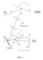
- the mechanical optical delay scanning apparatus functions by changing the grating input angle ( ⁇ i ), using a polygon scanning mirror 34, a galvanometer, resonant scanner, or a piezoelectric mirror tilter in the path of the incident beam 22.
- a telescope 36 is placed between the scanning mirror 34 and the grating 10 to avoid beam walkoff at the grating 10. If ⁇ is non-zero, the delay is scanned as the angle of the mirror 34 is scanned.
- the grating 10 can also be physically or mechanically scanned in angle using a galvanometer, a resonant scanner, or a piezoelectric mirror tilter.
- a small light weight grating can be placed on the rotating shaft of a galvanometer to achieve a steerable grating 10.
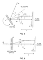
- the grating 40 may be radially scanned (Fig. 6).
- the HOE 40 changes the transmitted diffraction angle ( ⁇ ) of a beam as it is rotated.
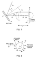
- One simple configuration consists of a circular element 42 with wedge subsections 44 (Fig. 9a).
- Each wedge consists of a diffraction grating with grating spacing (d) that varies as a function of angle ( ⁇ ) (Fig. 9b).
- d and ⁇ ( ⁇ ) change, producing a varying group delay.
- the change in grating spacing d diffracts the beam at a different angle ⁇ .
- the holographic scanner 42 is only used with monochromatic light.
- the grating 10 can spatially disperse a broad bandwidth source. This property is advantageous for phase control because the rotating HOE grating 42 can replace both the grating 10 and the angular scanner 18,34 (Figs. 1 and 4, respectively).
- the angle ( ⁇ ) of the mirror 18 following the grating 10 and lens 14 can be scanned using a polygon scanning mirror, a galvanometer, resonant scanner, or a piezoelectric mirror tilter.
- a polygonal scanning mirror 46 (Fig. 8) consists of a machined polygon 47 with highly reflecting facets 48.
- a high speed motor (not shown) is used to rotate the polygon 47.
- the input beam 22 is reflected off of one of the facets 48, producing an angular scan.
- air bearing motors are available that can scan at up to 40,000 rpm, a polygonal scanning mirror 46 with 24 facets 48 can produce 16,000 angular scans per second. This technology is well-suited for generating linear angular scans at high speeds.
- a galvanometer used for linear mechanical scanning of optical delay includes a retroreflector or corner cube mounted on a lever arm. Due to mechanical resonances and the large force required to drive the relatively high moment of inertia associated with a retroreflector mounted to a lever arm, the maximum frequency of galvanometer-based linear translators is typically only approximately 100 Hz.
- the galvanometer is similar in structure to a torque motor, consisting of a mirror mounted to a moving magnet rotor positioned between stator coils. The stator coils can provide a variable magnetic field which causes the rotor to turn. Without the large mass of a lever arm, this device is capable of angular scanning with high linearity and frequencies up to a few kHz.
- Scanning frequencies are maximized by reducing the mass of the rotor and attached mirror.
- the mirror must be small in size, limiting the maximum beam size on the mirror.
- a linear angular scan is possible because the galvanometer is heavily damped to prevent coupling into its natural mechanical resonances.
- a resonant scanner can also be used.
- the resonant scanner only oscillates at or near its mechanical resonance frequency.
- resonant scanners produce a sinusoidal change in angle as a function of time. If the near linear portions of the rising and falling edges of the sinusoidal angular scan are used, a 66% duty cycle can be achieved with a 2:1 slope change.
- the resonant scanner can provide a 66% duty cycle with a signal-to-noise (SNR) loss that is dependent on the noise equivalent bandwidth (NEB).
- SNR signal-to-noise
- the resonant scanner can oscillate at speeds up to 20 kHz, permitting its use for real time OCT imaging if the decreased SNR is acceptable.
- images of 500 pixels at 15 to 30 image frames per second correspond to 7.5 to 15 kHz scan frequencies.
- a resonant galvanometer can be used with resulting nonlinear phase and group delays as a function of time.
- This nonlinear behavior can be compensated using post-detection electronic processing as is known in the art (e.g., a Doppler tracking receiver).
- post-detection electronic processing e.g., a Doppler tracking receiver.
- the heterodyne frequency can be adjusted.
- the heterodyne frequency can be adjusted without affecting the group delay.
- the grating 10 and lens 14 are located on an axis which intercepts the axis of the tilting mirror 18, group delay is produced without changing the phase delay.
- This configuration can be used to apply an external modulation to the local oscillator for optimal matching of the optical heterodyne frequency to the system demodulation electronics or for performing homodyne detection in an OCT imaging system.
- a double passed configuration can be used in all of the scanning methods described above to ensure that the incident optical path 22 is coaxial with the reflected optical path.
- the double passed configuration eliminates the lateral offset of the reflected beam 23 (shown in Fig. 1) and thus improves the coupling efficiency back into the light path 22. All of the above methods provide a way to change both optical group delay and phase delay, thus allowing control over the optical fringe modulation frequency.
- phase control optical delay can be a versatile method for producing a scanning optical group delay.
- Phase control is a technique that uses a lens-grating pair 10,14 to alter the temporal properties of ultrafast pulses by manipulating the spectrum. This technique has been used for the temporal shaping of ultrafast pulses.
- a schematic of the generic pulse shaping apparatus is shown in Fig. 10.
- the pulse shaping apparatus consists of two identical reflection grating-lens pairs 10,14 and an amplitude, A(x), and/or phase, ⁇ ( x ) mask 50 placed midway between and one focal length, f , away from both lenses 14.
- the grating disperses the spectrum of the incident optical beam.
- the Fourier transform of the dispersed optical beam 24 occurs at the mask 50.
- the mask 50 modifies the spectrum either by phase or amplitude modulation.
- the modified spectrum is inverse Fourier transformed by the second lens 14b, causing an alteration of the temporal profile of the pulse.
- This transmission system can be used for delay line scanning in OCT systems.
- the pulse shaping apparatus employs a folded geometry configuration (Figure 11).
- Figure 11 This configuration has two advantages. First, only one grating-lens pair 10,14 is used. In addition, the folded geometry enables coupling back into the reference arm collimating lens 15 and optical fiber 17 without additional optical components.
- Phase manipulation can provide optical group delay by dispersing the spectrum with a grating and then applying a temporally modulated linear wavelength dependent phase.
- the wavelength dependent angular diffraction of the incident collimated beam is given by the grating equation, where m is the diffracted order of the reflected beam 24, d is the ruling spacing of the grating 10, and ⁇ i is the incident angle on the grating 10.
- the Fourier transform of the input beam now resides at the plane of the mirror 18. Since the Fourier transform of a linear phase ramp in the spectral domain corresponds to a delay in the time domain, a temporal group delay is obtained by placing a phase mask at the mirror, and is described by:
- the modified spectrum is then inverse Fourier transformed by propagating back through the folded phase control apparatus, creating a temporal delay of the input beam 22.
- the magnitude of the optical delay is proportional to the spectral dispersion of the grating 10, the focal length of the lens 14, and the slope of the phase ramp, ⁇ . Note that as described later by offsetting the center of rotation of the mirror 18 (Fig. 1a) with respect to the chief ray at angle ⁇ 0 , the phase control device can be used to independently adjust the phase delay and group delay.
- phase-mask-mirror combination can be replaced with a single tilted mirror (Fig. 11). If the mirror 18 is tilted with an angle ( ⁇ ), a linear wavelength dependent phase is applied to the incident beam 24.
- a 100 Hz linear scanning group delay line using a piezoelectric mirror tilter has been previously presented for construction of a high speed autocorrelator to measure pulse durations.
- One difficulty with using a tilted mirror 18 to produce the group delay is that the light 26 reflected from the tilted mirror 18 is no longer collinear with the incident beam 24. Beam walkoff due to deflection by the tilted mirror 18 limits coupling of the reflected beam 26 back into the reference arm collimating lens 15 and single mode fiber 17 (Fig. 12).
- One solution is to use a double pass configuration (Fig. 13). In this configuration, the beam emerging from the collimating lens 15 is decentered on grating 10 so the diffracted beam 24 is decentered on the lens 14. The beam 24 is refracted by the lens 14, which is corrected for spherical aberration, onto the tilted mirror 18. The tilted mirror 18 reflects the beam 26 through the lower portion of the lens 14.
- the light is then diffracted off the grating 10 and onto the double pass mirror 19.
- the double pass mirror 19 is aligned to allow the beam 26 to retrace its path back to the collimator.
- This configuration allows the folded configuration to be used with a tilted mirror 18 while avoiding beam walkoff and resultant coupling losses into the optical fiber 17 or equivalent source.
- the phase control apparatus is double passed, the delay produced for a given mirror tilt is also doubled. All of the devices described can use some form of this double pass geometry.
- Another advantage of the phase control apparatus for OCT is the capability to compensate dispersion mismatch between the reference and sample arms.
- An analysis performed to determine the group velocity dispersion (GVD) for a grating compressor describes the dispersion in the double passed configuration to be,
- phase control apparatus enables compensation of the dispersion imbalance between the reference and sample arms in the OCT system by simply changing the lens-grating separation.
- phase control paradigm One powerful aspect of the phase control paradigm is its versatility. Analysis has revealed that altering any one of several optical comments in the phase control apparatus can produce a change in group delay (Fig. 14). Specifically, a scanning group delay can be obtained by tilting the mirror 18, changing the incident angle ⁇ i on the grating 10, tilting the grating 10, or changing the grating spacing d .
- a simple ray trace analysis can be used to determine an approximate analytical expression for the group delay produced by changing the Fourier plane mirror tilt 10 by an angle, ⁇ .
- the diffracted angle for the center wavelength of the source is the diffracted angle for the center wavelength of the source.
- the change in group delay is twice that of equation (11) for the double passed phase control system.
- d 150 lines per mm
- ⁇ 10°
- f 10 cm
- ⁇ x ( ⁇ max , ⁇ min ) f (tan[ ⁇ ( ⁇ max )]-tan[ ⁇ ( ⁇ min )]), determines the maximum allowable mirror size for the rapid scanning delay line.
- the beam spread is 3 mm.
- the mirror 18 must be at least 3 mm or clipping of the spectrum will occur, resulting in the convolution of the autocorrelation function with a sinc function. For this reason, other configurations of the phase control apparatus that do not require a moving mirror 18, can be utilized for high resolution applications.
- Optical group delay may also be produced by scanning the grating incident beam angle, ⁇ i , using a scanning component 58 such as a rotating polygon mirror, a galvanometer, or a resonant scanner (Fig. 14).
- a scanning component 58 such as a rotating polygon mirror, a galvanometer, or a resonant scanner (Fig. 14).
- the configuration differs from the previous method by the inclusion of a fixed angle, ⁇ , a device for scanning ⁇ i , and a telescope 56 between the scanning mirror 58 and the grating 10. Since the tilted mirror 18 is fixed, it can be large enough to accommodate any bandwidth source.
- the telescope 56 is inserted between the scanning component 58 and the grating 10 to prevent beam walkoff at the grating 10. To accomplish this, the image and object planes of the telescope 56 must match the positions of the scanning mirror 58 and the grating 10.
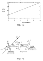
- Angular scanning of the grating 10 in the folded phase control apparatus also creates a group delay (Fig. 16).
- the primary advantage to this configuration is that a telescope 56 is not necessary because beam walkoff at the grating 10 does not occur. This approach requires placing a grating 10 on a galvanometer mirror or polygon scanning mirror as shown.
- the phase control apparatus permits high speed group delay scanning.
- the grating 10 is a transmission HOE, such as that shown in Figure 9, the groove density of the grating may be scanned in a rapid fashion. This may be accomplished by using a rotating circular HOE 42 with grating spacing that varies as a function of angle. As the HOE 42 is rotated, the change in grating spacing alters the extent of the spectral spreading (Fig. 17). Since the wavelength dependent phase delay is proportional to ruling of the grating, rotating the HOE 42 also produces a scanning group delay.
- a more elegant method for changing the grating groove density is the use of an AOM 28 (Fig. 18).
- the wavelength spread is augmented by directing the light 24 transmitted through the AOM 28 through a diffraction grating 32 ( Figure 18).
- the diffraction grating 32 is necessary because the change in grating spacing (RF bandwidth) for commercially available AOMs 28 is not sufficient to produce an adequate group delay scan for OCT.
- a telescope (not shown) with a high magnification can be placed between the AOM 28 and the grating 32 to enhance the change in diffraction provided by the AOM 28.
- a plot of the path length delay produced by an AOM-diffraction grating pair 28,32 as a function of the RF driving frequency is presented in Figure 19.
- the secondary diffraction grating had a ruling of 1200 lines per mm.
- the group delay produced by this configuration is nonlinear.
- This nonlinearity can be corrected during a group delay scan by modifying the RF waveform sweep frequency. This can be beneficial when the delay line apparatus is used in OCT systems. In addition, changes in frequency dependent diffraction efficiency can be compensated for by altering the RF signal amplitude.
- Another difference between the AOM scanning method is that a Doppler shift (2 ⁇ RF ) is transferred to the local oscillator signal. This modulation frequency may be removed by using the AOM 28 in a double pass configuration.
- the AOM configuration is preferable over the mechanical angular scanning configurations because it allows real time (15 kHz) path length scanning with no moving parts.
- the phase delay In order to use the scanning path length delay lines presented in the previous section, the phase delay must be analyzed to determine the heterodyne modulation frequency. Unlike other rapid scanning optical delay lines, such as the linear mechanical translator or the piezoelectric optical fiber stretcher, the change in phase delay using the phase control method is not directly related to the change in group delay.
- the center wavelength In Fig. 20, the center wavelength is directed towards the tilting mirror 18 and is offset from the axis of rotation by x 0 . If the mirror surface 60 approximately intersects the axis of rotation 62, the phase delay can be written as, which is a modification of equation. (8) that incorporates a lateral offset of the galvanometer.
- the heterodyne modulation frequency for a source with a Gaussian spectral distribution is determined by the phase shift at the center wavelength, ⁇ ( ⁇ , t )
- the interferometric signal consists of the envelope of the autocorrelation function without any modulation. This can be useful for OCT imaging systems that perform homodyne detection. This feature of the tilting mirror configuration can be advantageous. If an independent phase modulation is applied to the local oscillator, the system would be capable of scanning at different speeds without changing the center frequency of the band pass filter before demodulation. A phase diversity homodyne detection system would be useful for OCT in this instance.
- an arbitrary modulation frequency can be applied to the local oscillator.
- the modulation frequency i.e., phase delay
- the range of center modulation frequencies that may be achieved is only limited by spectral vignetting due to the finite size of the scanning mirror 18.
- the group-phase delay independence of the phase control apparatus is an advantage for scanning mirrors 18 with an axis of rotation 62 that intersects the mirror surface 60.
- the group-delay and phase-delay properties are more complex.
- the group-delay is linear in angle but not in phase delay.
- a polygon mirror 46 is the optimal scanning device for rapidly changing the angle, ⁇ (Fig. 21).
- x 0 changes across a single scan, where ⁇ is the rotation angle and ⁇ 0 is the angle at which the center wavelength of the source is coincident with the center of the polygon mirror facet.
- ⁇ - ⁇ 0 the angle at which the center wavelength of the source is coincident with the center of the polygon mirror facet.
- x 0 is a linear function of t .
- the change in group delay produced by the polygon scanning mirror 46 is linear, the change in phase is quadratic as a function of time. Since the modulation frequency shifts linearly over the scan, the polygon scanning mirror 46 cannot be used in conjunction with a demodulation method that incorporates a fixed band pass filter. This is an unfortunate result because the polygon scanning mirror 46 is the best mechanical means for obtaining high speed (> 1 kHz) linear group delays.
- the varying modulation frequency can be overcome, however, by using an alternative demodulation scheme, such as adaptive frequency mixing detection, where the frequency at which the demodulation is performed is varied to track the variation in the modulation frequency. This scheme is particularly well suited for OCT imaging applications.
- phase control configurations such as scanning the grating angle of incidence ⁇ i or the grating ruling density, also produce a nonlinear phase delay.
- the phase shift becomes As with the polygon scanning mirror 46, the phase is a nonlinear function of time and again, these methods can only be used in conjunction with an adaptive frequency mixing demodulation scheme for OCT imaging applications.
- a Doppler tracking or adaptive frequency mixing detection method which tracks the changing IF heterodyne frequency is useful, especially for OCT imaging systems.
- phase control optical delay Typical operating parameters for one embodiment of the phase control optical delay are given in terms of an experimental example. Scanning the angle, ⁇ , with a galvanometer produces a linear optical group delay scan with a constant modulation frequency. Because the demodulation electronics used in this study required a constant modulation frequency, a folded double passed scanning mirror configuration was used to perform coherence gating in the high speed OCT system.
- a self-phase modulated Kerr Lens Modelocked Cr4+:Forsterite laser was used as the source of low coherence light for the high speed OCT system.
- the laser was set to an output power of 30 mW.
- the sample arm power was 12 mW.
- the FWHM spectrum of the source was 75 nm, corresponding to a Gaussian autocorrelation FWHM of 10 ⁇ m.
- the center of the beam was offset on the scanning mirror 18 to produce a modulation frequency of 750 kHz.
- the FWHM bandwidth of the signal was approximately 350 kHz. This modulation frequency was chosen to enable band pass filtering of the interferometric signal without accepting any contributions from low frequency noise.
- the mirror size was minimized to a width of 6 mm. Because of this constraint, the full bandwidth of the self-phase modulated source was not used. If the entire spectrum was employed (200 nm), one side of the spectrum would have been clipped by the edges of the scanning mirror.
- the galvanometer was driven with a 1 kHz triangle waveform, enabling 2000 scans per second, twice the speed of the PZT-based high speed OCT system.
- This rapid scanning rate enabled image acquisition at 4 frames per second for an image size of 512 (lateral) x 256 (axial) pixels or 8 frames per second for an image size of 256 (lateral) x 256 (axial) pixels.
- the phase control method produced axial scans that were not corrupted by dropout artifacts due to hysteresis.
- the total galvanometer scan angle of 3° provided an optical path length delay of 3 mm.
Landscapes
- Physics & Mathematics (AREA)
- Health & Medical Sciences (AREA)
- Life Sciences & Earth Sciences (AREA)
- General Physics & Mathematics (AREA)
- Pathology (AREA)
- General Health & Medical Sciences (AREA)
- Optics & Photonics (AREA)
- Public Health (AREA)
- Veterinary Medicine (AREA)
- Heart & Thoracic Surgery (AREA)
- Medical Informatics (AREA)
- Molecular Biology (AREA)
- Surgery (AREA)
- Animal Behavior & Ethology (AREA)
- Engineering & Computer Science (AREA)
- Biophysics (AREA)
- Biomedical Technology (AREA)
- Radiology & Medical Imaging (AREA)
- Nuclear Medicine, Radiotherapy & Molecular Imaging (AREA)
- Spectroscopy & Molecular Physics (AREA)
- Chemical & Material Sciences (AREA)
- Analytical Chemistry (AREA)
- Biochemistry (AREA)
- Immunology (AREA)
- Investigating Or Analysing Materials By Optical Means (AREA)
- Instruments For Measurement Of Length By Optical Means (AREA)
- Length Measuring Devices By Optical Means (AREA)
Claims (31)
- Optische Verzögerungsleitungsvorrichtung mit:wobei mindestens eines der Mehrzahl von optischen Elementen ein dispersives Element ist, das imstande ist, das optische Spektrum des optischen Signals räumlich zu dispergieren, um ein räumlich dispergiertes optisches Signal bereitzustellen, dadurch gekennzeichnet, dasseiner optischen Eingabe;einer optischen Ausgabe; undeiner Mehrzahl von optischen Elementen (10, 14, 18) in Kommunikation miteinander, um ein optisches Signal mit einem optischen Spektrum von der optischen Eingabe zu der optischen Ausgabe zu führen,
mindestens eines der Mehrzahl von optischen Elementen einstellbar ist, um wiederholt abzutasten, um mindestens die Phasenverzögerung und/oder die Gruppenverzögerung des optischen Signals zwischen der optischen Eingabe und der optischen Ausgabe zu beeinflussen, um dadurch eine im Wesentlichen unabhängige Variation der Phasen- und Gruppenverzögerung zu ermöglichen. - Optische Verzögerungsleitungsvorrichtung gemäß Anspruch 1, ferner mit einem optischen Bildgebungsmodul (14) und einem reflektierenden Element (18), die jeweils in optischer Kommunikation mit dem dispersiven Element (14) sind, wobei das dispersive Element ein winkelmäßig dispergiertes optisches Signal mit spektralen Komponenten erzeugt, wobei das optische Bildgebungsmodul ein Bild des winkelmäßig dispergierten optischen Signals an dem reflektierenden Element erzeugt, wobei sich das reflektierende Element um eine Achse dreht, die von der Schwerpunktwellenlänge des Bildes verschiebbar ist, um die Phasenverzögerung einzustellen, und wobei der Winkel des reflektierenden Elements änderbar ist; um die Gruppenverzögerung einzustellen.
- Optische Verzögerungsleitungsvorrichtung gemäß Anspruch 1, bei der das dispersive Element ein Beugungsgitter (10) ist, und wobei die Gruppenverzögerung durch Ändern des relativen Winkels zwischen der Normalen des Beugungsgitters und dem einfallenden Lichtstrahl einstellbar ist.
- Optische Verzögerungsleitungsvorrichtung gemäß Anspruch 1, bei der das dispersive Element eine räumlich periodische Struktur aufweist, die Wellenlängenkomponenten des optischen Spektrums des optischen Signals räumlich dispergiert, und wobei die Gruppenverzögerung durch Ändern der räumlich periodischen Struktur des dispersiven Elements eingestellt wird.
- Optische Verzögerungsleitungsvorrichtung gemäß Anspruch 1, bei der das dispersive Element einen akusto-optischen Modulator (28) mit einer einstellbaren räumlich periodischen Struktur umfasst, die sich als Reaktion auf einen von dem akusto-optischen Modulator (28) empfangenen Funkfrequenztreibersignalverlauf verändert.
- Optische Verzögerungsleitungsvorrichtung gemäß Anspruch 5, bei der der Funkfrequenztreibersignalverlauf wiederholt geändert wird, um eine sich wiederholende und im Wesentlichen konstante Änderungsrate der Gruppenverzögerung zu erzeugen.
- Optische Verzögerungsleitungsvorrichtung gemäß Anspruch 6, bei der der Funkfrequenztreibersignalverlauf wiederholt geändert wird, um eine sich wiederholende Änderung in der Gruppenverzögerung mit einem im Wesentlichen konstanten optischen Durchsatzwirkungsgrad zu erzeugen.
- Optische Verzögerungsleitungsvorrichtung gemäß Anspruch 1, bei der ein weiteres der Mehrzahl von optischen Elementen in einer Konfiguration mit zweifachem Durchlauf ist.
- Optische Verzögerungsleitungsvorrichtung gemäß Anspruch 1, bei der die Verzögerungsleitung die Eigenschaft aufweist, dass beim interferometrischen Kombinieren des durch die optische Verzögerungsleitung übertragenen optischen Signals mit einem Teil des optischen Signals, das nicht durch die Verzögerungsleitung übertragen wird, ein Heterodynsignal mit einer Frequenz ungleich Null erzielt wird.
- Optische Verzögerungsleitungsvorrichtung gemäß Anspruch 1, bei der mindestens eines der Mehrzahl von optischen Elementen einstellbar ist, um die Phasenverzögerung und die Gruppenverzögerung des optischen Signals unabhängig zu beeinflussen.
- Optisches interferometrisches Bildgebungssystem zur Bildgebung einer Probe mit:wobei mindestens eines der Mehrzahl von optischen Elementen einstellbar ist, um wiederholt abzutasten, um mindestens die Phasenverzögerung und/oder die Gruppenverzögerung des optischen Signals zwischen der optischen Eingabe und der optischen Ausgabe zu beeinflussen, um eine im Wesentlichen unabhängige Variation der Phasen- und Gruppenverzögerung zu ermöglichen.einer optischen Quelle, die imstande ist, ein optisches Signal mit einem optischen Spektrum zu erzeugen, die ein dispersives Element (10) umfasst, das imstande ist, das optische Spektrum des optischen Signals räumlich zu dispergieren, um ein räumlich dispergiertes optisches Signal bereitzustellen,einer Mehrzahl von optischen Elementen in optischer Kommunikation miteinander und in optischer Kommunikation mit der Quelle; gekennzeichnet durchein Interferometer (13) in optischer Kommunikation mit der optischen Quelle; undeinen Detektor (21) in optischer Kommunikation mit dem Interferometer (13), wobei der Detektor in elektrischer Kommunikation mit einem Prozessor ist, wobei der Prozessor Bilder von optischen Mikrostruktureigenschaften der Proben erzeugt,
- Bildgebungssystem gemäß Anspruch 11, bei dem mindestens ein einstellbares optisches Element (28) wiederholt abtastet, um eine im Wesentlichen gleichmäßige Änderungsrate der optischen Gruppenverzögerung und eine zeitlich veränderliche optische Phasenverzögerung zu erzeugen, und wobei der Prozessor die zeitlich veränderliche optische Phasenverzögerung kompensiert.
- Optisches interferometrisches Bildgebungssystem gemäß Anspruch 11, bei dem das Interferometer ferner umfasst:einen Probenarm zum Empfangen einer optischen Signalprobe;einen Bezugsarm in optischer Kommunikation mit der optischen Verzögerungsleitungsvorrichtung;ein optisches Bildgebungsmodul, das positioniert ist, und das räumlich dispergierte, verzögerte optische Signal von der optischen Verzögerungsleitungsvorrichtung und das optische Probensignal von dem Probenarm zu empfangen; undein reflektierendes Element in optischer Kommunikation mit dem optischen Bildgebungsmodul; wobei das reflektierende Element fern von der Fourierebene des dispergierten optischen Spektrums platziert ist, um die Gruppengeschwindigkeitsdispersion der ersten Ordnung zwischen dem Probenarm und dem Bezugsarm auszugleichen.
- Optisches Bildgebungssystem gemäß Anspruch 13, ferner mit einer Signalverarbeitungseinheit (25) in elektrischer Kommunikation mit dem Detektor (21), und wobei das einstellbare optische Element wiederholt abgetastet wird, und die Signalverarbeitungseinheit jede nicht gleichmäßige Änderungsrate der Phasenverzögerung kompensiert.
- Optisches interferometrisches Bildgebungssystem gemäß Anspruch 13, bei dem das räumlich dispersive Element ein beugendes Element umfasst.
- Optisches interferometrisches Bildgebungssystem gemäß Anspruch 13, ferner mit einem akusto-optischen Modulator (28) in optischer Kommunikation mit der optischen Verzögerungsleitung.
- Optisches interferometrisches Bildgebungssystem gemäß Anspruch 13, ferner mit einer elektro-optischen Strahlenablenkeinrichtung in optischer Kommunikation mit der optischen Verzögerungsleitung.
- Optisches interferometrisches Bildgebungssystem gemäß Anspruch 13, bei dem das einstellbare optische Element einen Polygonabtastspiegel (46) umfasst.
- Optisches interferometrisches Bildgebungssystem gemäß Anspruch 13, bei dem das räumlich dispersive Element eine periodische optische Struktur mit einer einstellbaren Periode aufweist, wobei das räumlich dispersive Element das optische Signal winkelmäßig dispergiert.
- Optisches interferometrisches Bildgebungssystem gemäß Anspruch 13, bei dem das räumlich dispersive Element ein holographisches optisches Element (40) umfasst.
- Optisches interferometrisches Bildgebungssystem gemäß Anspruch 13, bei dem das reflektierende Element ein rotierender Polygonspiegel (46) ist.
- Ein Abtast-OCT-Bildgebungssystem mit:wobei das Interferometer das verzögerte optische Signal mit einem Abschnitt des optischen Signals von einer Probe kombiniert, und wobei der Detektor das interferometrische kombinierte Signal erfasst, wobei ein Heterodyn- oder Homodynsignal mit einer Frequenz im Wesentlichen gleich Null als Reaktion darauf erzeugt, und;einer optischen Quelle, die imstande ist, ein optisches Signal mit einem optischen Spektrum zu erzeugen; gekennzeichnet durch:ein Interferometer in Kommunikation mit der optischen Quelle;einen Detektor in optischer Kommunikation mit dem Interferometer;einen Signalprozessor (25) in elektrischer Kommunikation mit dem Detektor;eine optische Verzögerungsleitung (11) in optischer Kommunikation mit dem Interferometer, die imstande ist, das optische Signal zu verzögern,eine Abtastvorrichtung, die imstande ist, die einstellbaren optischen Elemente einzustellen, wodurch die optische Gruppenverzögerung gesteuert wird;
einer Mehrzahl von einstellbaren optischen Elementen, die imstande sind, das optische Signal räumlich zu dispergieren und eine optische Gruppenverzögerung des optischen Signals zu beeinflussen, um eine im Wesentlichen unabhängige Variation der Phasen- und Gruppenverzögerung zu ermöglichen, wodurch der Signalprozessor Bilder der Probe als Reaktion auf das Heterodyn- oder Homodynsignal erzeugt. - Optisches interferometrisches Bildgebungssystem gemäß Anspruch 11 oder 13, ferner mit einer Konfiguration mit zweifachem Durchlauf.
- Verfahren zum Einstellen mindestens der Phasenverzögerungen und/oder der Gruppenverzögerung eines optischen Signals mit:Bereitstellen eines optischen Signals mit einem optischen Spektrum;Bereitstellen mindestens eines optischen Elements, bei dem ein Element ein dispersives Element ist;räumlichem Dispergieren des optischen Spektrums des optischen Signals unter Verwendung des dispersiven Elements;Empfangen des räumlich dispergierten optischen Signals; gekennzeichnet durchEinstellen des mindestens einen optischen Elements, um wiederholt abzutasten, um mindestens die Phasenverzögerung und/oder die Gruppenverzögerung des optischen Signals zu beeinflussen, um dadurch eine im Wesentlichen unabhängige Variation der Phasen- und Gruppenverzögerung zu ermöglichen.
- Verfahren gemäß Anspruch 24, bei dem das mindestens eine dispersive Element ein Beugungsgitter ist, und der Schritt des Einstellens durch Ändern des Winkels des Gitters durchgeführt wird.
- Verfahren gemäß Anspruch 24, bei dem das mindestens eine dispersive Element ein Beugungsgitter ist, und wobei der Schritt des Einstellens durch Ändern der Gitterfurchendichte durchgeführt wird.
- Verfahren gemäß Anspruch 24, bei dem das mindestens eine dispersive Element einen akusto-optischen Modulator (28) mit einer einstellbaren räumlich periodischen Struktur umfasst, die sich als Reaktion auf einen von dem akusto-optischen Modulator empfangenen Frequenztreibersignalverlauf verändert, wobei der Schritt des Einstellens durch Ändern der räumlichen Periodenstruktur des mindestens einen dispersiven Elements durchgeführt wird, und wobei der Funkfrequenztreibersignalverlauf wiederholt geändert wird, um eine sich wiederholende und im Wesentlichen konstante Änderungsrate der Gruppenverzögerung zu erzeugen.
- Verfahren zum Erzeugen eines Bildes einer Probe mit:Bereitstellen einer optischen Quelle; gekennzeichnet durch:Bereitstellen eines Detektors (21) in optischer Kommunikation mit der optischen Quelle;Bereitstellen eines Interferometers in Kommunikation mit der optischen Quelle und dem Detektor;Bereitstellen einer Probe (29) in der Nähe des Interferometers;Übertragen eines Signals von der optischen Quelle zu der Probe (29) und der optischen Verzögerungsleitung;Kombinieren eines Signals von der Probe und des räumlich dispergierten, verzögerten optischen Signals;Erfassen des kombinierten Signals und Erzeugen eines Bildes als Reaktion auf die Erfassung mittels eines Prozessors, der in elektrischer Kommunikation mit dem Detektor ist,Bereitstellen einer optischen Verzögerungsleitung (21), wobei die optische Verzögerungsleitung (21) einstellbare optische Elemente, die imstande sind, ein optisches Signal von der optischen Quelle räumlich zu dispergieren und mindestens die Phasenverzögerung und/oder die optische Gruppenverzögerung des räumlich dispergierten optischen Signals einzustellen, in optischer Kommunikation mit dem Interferometer umfasst; undEinstellen der einstellbaren Elemente durch wiederholtes Abtasten, wodurch mindestens die Phasenverzögerung und/oder die Gruppenverzögerung des von der optischen Signalleitung empfangenen optischen Signals beeinflusst wird, um dadurch eine im Wesentlichen unabhängige Variation der Phasen- und Gruppenverzögerung zu ermöglichen.
- Verfahren gemäß Anspruch 28, ferner mit einem wiederholten Abtasten des mindestens einen einstellbaren Elements, um eine im Wesentlichen gleichmäßige Änderungsrate der optischen Gruppenverzögerung und einer zeitlich veränderlichen optischen Phasenverzögerung zu erzeugen, und einem Kompensieren der zeitlich veränderliche optische Phase mit dem Prozessor.
- Ein Abtast-OCT-Bildgebungssystem mit:wobei die optische Verzögerungsleitung (11) einstellbare optische Elemente umfasst, die imstande sind, das optische Signal räumlich zu dispergieren und eine optische Gruppenverzögerung und eine optische Phasenverzögerung des optischen Signal zu beeinflussen; gekennzeichnet durch:einer optischen Quelle, die imstande ist, ein optisches Signal mit einem optischen Spektrum zu erzeugen;einer optischen Verzögerungsleitung (11) in optischer Kommunikation mit dem Interferometer,wobei das Interferometer das verzögerte optische Signal mit einem Abschnitt des optischen Signals von einer Probe interferometrisch kombiniert;ein Interferometer in Kommunikation mit der optischen Quelle;einen Detektor (21) in optischer Kommunikation mit dem Interferometer;einen Signalprozessor (25) in elektrischer Kommunikation mit dem Detektor (21);eine Vorrichtung, die imstande ist, die einstellbaren optischen Elemente einzustellen, wodurch eine Abtastung mindestens der optische Gruppenverzögerung und/oder der optischen Phasenverzögerung gesteuert wird;
wobei der Detektor (21) das interferometrische kombinierte Signal erfasst, wodurch ein Heterodynsignal mit einer Frequenz im Wesentlichen ungleich Null während mindestens eines Abschnitts der Abtastung erzeugt wird,
und wobei der Signalprozessor (25) ein Bild der Probe als Reaktion auf das Heterodynsignal mit einer Frequenz ungleich Null erzeugt. - Verfahren gemäß Anspruch 24 oder 30, ferner mit einem Bereitstellen einer Konfiguration mit zweifachem Durchlauf.
Applications Claiming Priority (3)
| Application Number | Priority Date | Filing Date | Title |
|---|---|---|---|
| US4673997P | 1997-05-16 | 1997-05-16 | |
| US46739P | 1997-05-16 | ||
| PCT/US1998/009914 WO1998052021A1 (en) | 1997-05-16 | 1998-05-15 | Grating based phase control optical delay line |
Publications (2)
| Publication Number | Publication Date |
|---|---|
| EP0981733A1 EP0981733A1 (de) | 2000-03-01 |
| EP0981733B1 true EP0981733B1 (de) | 2004-02-11 |
Family
ID=21945116
Family Applications (1)
| Application Number | Title | Priority Date | Filing Date |
|---|---|---|---|
| EP98922306A Expired - Lifetime EP0981733B1 (de) | 1997-05-16 | 1998-05-15 | Gitter-basierte optische verzögerungsleitung zur phasensteuerung |
Country Status (4)
| Country | Link |
|---|---|
| EP (1) | EP0981733B1 (de) |
| CA (1) | CA2289598C (de) |
| DE (1) | DE69821610T2 (de) |
| WO (1) | WO1998052021A1 (de) |
Cited By (6)
| Publication number | Priority date | Publication date | Assignee | Title |
|---|---|---|---|---|
| US10132610B2 (en) | 2013-06-23 | 2018-11-20 | Eric Swanson | Integrated optical system |
| US10401883B2 (en) | 2018-01-11 | 2019-09-03 | Eric Swanson | Optical probe using multimode optical waveguide and proximal processing |
| US10969571B2 (en) | 2016-05-30 | 2021-04-06 | Eric Swanson | Few-mode fiber endoscope |
| US11579356B2 (en) | 2013-06-23 | 2023-02-14 | Eric Swanson | Integrated optical system with wavelength tuning and spatial switching |
| US11852802B2 (en) | 2015-05-05 | 2023-12-26 | Eric Swanson | Optical instrument for imaging and sensing using multicore fiber |
| US12085387B1 (en) | 2023-09-23 | 2024-09-10 | Hamamatsu Photonics K.K. | Optical coherence tomography system for subsurface inspection |
Families Citing this family (18)
| Publication number | Priority date | Publication date | Assignee | Title |
|---|---|---|---|---|
| US6687010B1 (en) | 1999-09-09 | 2004-02-03 | Olympus Corporation | Rapid depth scanning optical imaging device |
| ATE493683T1 (de) * | 2001-04-07 | 2011-01-15 | Zeiss Carl Microimaging Gmbh | Verfahren und anordnung zur tiefenaufgelösten optischen erfassung einer probe |
| US7274446B2 (en) | 2001-04-07 | 2007-09-25 | Carl Zeiss Jena Gmbh | Method and arrangement for the deep resolved optical recording of a sample |
| US7253897B2 (en) | 2001-06-01 | 2007-08-07 | Cidra Corporation | Optical spectrum analyzer |
| EP1393026A1 (de) * | 2001-06-01 | 2004-03-03 | CiDra Corporation | Optischer kanalüberwacher |
| DE10150934A1 (de) * | 2001-10-09 | 2003-04-10 | Zeiss Carl Jena Gmbh | Verfahren und Anordnung zur tiefenaufgelösten Erfassung von Proben |
| DE10260887A1 (de) * | 2002-12-17 | 2004-07-01 | Carl Zeiss | Kohärenzmikroskop |
| CN103293126B (zh) * | 2003-10-27 | 2017-03-01 | 通用医疗公司 | 用于使用频域干涉测量法进行光学成像的方法和设备 |
| JP4895255B2 (ja) | 2005-09-22 | 2012-03-14 | 富士フイルム株式会社 | 共焦点顕微鏡装置 |
| JP2007085931A (ja) | 2005-09-22 | 2007-04-05 | Fujinon Corp | 光断層画像化装置 |
| JP5550258B2 (ja) | 2009-05-08 | 2014-07-16 | キヤノン株式会社 | 光干渉断層撮像装置 |
| US9134109B2 (en) | 2010-04-30 | 2015-09-15 | Hamamatsu Photonics K.K. | Phase image acquisition device |
| DE102011078089A1 (de) * | 2011-06-27 | 2012-12-27 | Robert Bosch Gmbh | Verfahren und Anordnung zur Abstandsmessung bei einer Laserbearbeitungsanlage |
| US10741910B2 (en) | 2017-06-28 | 2020-08-11 | Eric Swanson | Integrated photonic array fed by free-space optics |
| JP7297319B2 (ja) | 2018-07-06 | 2023-06-26 | 国立大学法人 東京大学 | 高速スキャンフーリエ変換分光装置及び分光方法 |
| US11681093B2 (en) | 2020-05-04 | 2023-06-20 | Eric Swanson | Multicore fiber with distal motor |
| US11802759B2 (en) | 2020-05-13 | 2023-10-31 | Eric Swanson | Integrated photonic chip with coherent receiver and variable optical delay for imaging, sensing, and ranging applications |
| CN111707366B (zh) * | 2020-07-23 | 2024-03-15 | 中国工程物理研究院流体物理研究所 | 基于光纤多普勒干涉的实时高精度延时传感装置 |
Family Cites Families (3)
| Publication number | Priority date | Publication date | Assignee | Title |
|---|---|---|---|---|
| US3549239A (en) * | 1968-11-19 | 1970-12-22 | United Aircraft Corp | Optical signal processor |
| US3961841A (en) * | 1970-09-23 | 1976-06-08 | Joseph Anthony Giordmaine | Optical pulse position modulator |
| DE69227902T3 (de) * | 1991-04-29 | 2010-04-22 | Massachusetts Institute Of Technology, Cambridge | Vorrichtung für optische abbildung und messung |
-
1998
- 1998-05-15 EP EP98922306A patent/EP0981733B1/de not_active Expired - Lifetime
- 1998-05-15 DE DE69821610T patent/DE69821610T2/de not_active Expired - Lifetime
- 1998-05-15 WO PCT/US1998/009914 patent/WO1998052021A1/en not_active Ceased
- 1998-05-15 CA CA002289598A patent/CA2289598C/en not_active Expired - Lifetime
Cited By (10)
| Publication number | Priority date | Publication date | Assignee | Title |
|---|---|---|---|---|
| US10132610B2 (en) | 2013-06-23 | 2018-11-20 | Eric Swanson | Integrated optical system |
| US10422623B2 (en) | 2013-06-23 | 2019-09-24 | Eric Swanson | Wavelength tunable laser device |
| US10876827B2 (en) | 2013-06-23 | 2020-12-29 | Eric Swanson | Multi-cavity wavelength tunable laser device |
| US11041710B2 (en) | 2013-06-23 | 2021-06-22 | Eric Swanson | Wavelength tunable laser device using frequency shifter |
| US11579356B2 (en) | 2013-06-23 | 2023-02-14 | Eric Swanson | Integrated optical system with wavelength tuning and spatial switching |
| US11852802B2 (en) | 2015-05-05 | 2023-12-26 | Eric Swanson | Optical instrument for imaging and sensing using multicore fiber |
| US10969571B2 (en) | 2016-05-30 | 2021-04-06 | Eric Swanson | Few-mode fiber endoscope |
| US10401883B2 (en) | 2018-01-11 | 2019-09-03 | Eric Swanson | Optical probe using multimode optical waveguide and proximal processing |
| US10809750B2 (en) | 2018-01-11 | 2020-10-20 | Eric Swanson | Optical probe |
| US12085387B1 (en) | 2023-09-23 | 2024-09-10 | Hamamatsu Photonics K.K. | Optical coherence tomography system for subsurface inspection |
Also Published As
| Publication number | Publication date |
|---|---|
| EP0981733A1 (de) | 2000-03-01 |
| JP2001527659A (ja) | 2001-12-25 |
| DE69821610T2 (de) | 2004-12-23 |
| WO1998052021A1 (en) | 1998-11-19 |
| CA2289598C (en) | 2004-07-20 |
| CA2289598A1 (en) | 1998-11-19 |
| DE69821610D1 (de) | 2004-03-18 |
| JP4065963B2 (ja) | 2008-03-26 |
Similar Documents
| Publication | Publication Date | Title |
|---|---|---|
| US6111645A (en) | Grating based phase control optical delay line | |
| CA2289598C (en) | Grating based phase control optical delay line | |
| EP1364239B1 (de) | Optische verzögerungsleitung | |
| US5321501A (en) | Method and apparatus for optical imaging with means for controlling the longitudinal range of the sample | |
| US7133138B2 (en) | Rapid depth scanning optical imaging device | |
| US5975697A (en) | Optical mapping apparatus with adjustable depth resolution | |
| TWI463177B (zh) | 使用頻率域干涉法用以執行光學成像之方法及設備 | |
| EP1687586B1 (de) | Spektrales interferometrieverfahren und vorrichtung | |
| JP2011527218A (ja) | 改善された内視鏡 | |
| WO2001042735A1 (en) | Optical mapping apparatus with adjustable depth resolution | |
| CN100464697C (zh) | 用于oct平衡探测的透射式快速光学扫描延迟线 | |
| CN201026206Y (zh) | 一种基于光学扫描延迟线的谱域oct成像装置 | |
| US20040257581A1 (en) | Real-time imaging and analysis system | |
| CN201094621Y (zh) | 一种用于oct平衡探测的透射式快速光学扫描延迟线 | |
| JP4065963B6 (ja) | 格子ベース位相制御光学遅延線 | |
| JP3938448B2 (ja) | 光学的断層像撮影装置 | |
| US20250268467A1 (en) | Optical coherence tomography instrument and optical coherence tomography method |
Legal Events
| Date | Code | Title | Description |
|---|---|---|---|
| PUAI | Public reference made under article 153(3) epc to a published international application that has entered the european phase |
Free format text: ORIGINAL CODE: 0009012 |
|
| 17P | Request for examination filed |
Effective date: 19991112 |
|
| AK | Designated contracting states |
Kind code of ref document: A1 Designated state(s): DE FR GB |
|
| 17Q | First examination report despatched |
Effective date: 20001013 |
|
| GRAH | Despatch of communication of intention to grant a patent |
Free format text: ORIGINAL CODE: EPIDOS IGRA |
|
| GRAS | Grant fee paid |
Free format text: ORIGINAL CODE: EPIDOSNIGR3 |
|
| GRAA | (expected) grant |
Free format text: ORIGINAL CODE: 0009210 |
|
| AK | Designated contracting states |
Kind code of ref document: B1 Designated state(s): DE FR GB |
|
| REG | Reference to a national code |
Ref country code: GB Ref legal event code: FG4D |
|
| REF | Corresponds to: |
Ref document number: 69821610 Country of ref document: DE Date of ref document: 20040318 Kind code of ref document: P |
|
| ET | Fr: translation filed | ||
| PLBE | No opposition filed within time limit |
Free format text: ORIGINAL CODE: 0009261 |
|
| STAA | Information on the status of an ep patent application or granted ep patent |
Free format text: STATUS: NO OPPOSITION FILED WITHIN TIME LIMIT |
|
| 26N | No opposition filed |
Effective date: 20041112 |
|
| REG | Reference to a national code |
Ref country code: DE Ref legal event code: R082 Ref document number: 69821610 Country of ref document: DE Representative=s name: MAI DOERR BESIER EUROPEAN PATENT ATTORNEYS - E, DE Ref country code: DE Ref legal event code: R082 Ref document number: 69821610 Country of ref document: DE Representative=s name: MAI DOERR BESIER PATENTANWAELTE, DE |
|
| REG | Reference to a national code |
Ref country code: FR Ref legal event code: PLFP Year of fee payment: 19 |
|
| REG | Reference to a national code |
Ref country code: FR Ref legal event code: PLFP Year of fee payment: 20 |
|
| PGFP | Annual fee paid to national office [announced via postgrant information from national office to epo] |
Ref country code: GB Payment date: 20170530 Year of fee payment: 20 Ref country code: DE Payment date: 20170530 Year of fee payment: 20 Ref country code: FR Payment date: 20170525 Year of fee payment: 20 |
|
| REG | Reference to a national code |
Ref country code: DE Ref legal event code: R071 Ref document number: 69821610 Country of ref document: DE |
|
| REG | Reference to a national code |
Ref country code: GB Ref legal event code: PE20 Expiry date: 20180514 |
|
| PG25 | Lapsed in a contracting state [announced via postgrant information from national office to epo] |
Ref country code: GB Free format text: LAPSE BECAUSE OF EXPIRATION OF PROTECTION Effective date: 20180514 |