EP0981776B1 - Microscope confocal a haute resolution - Google Patents
Microscope confocal a haute resolution Download PDFInfo
- Publication number
- EP0981776B1 EP0981776B1 EP97943446A EP97943446A EP0981776B1 EP 0981776 B1 EP0981776 B1 EP 0981776B1 EP 97943446 A EP97943446 A EP 97943446A EP 97943446 A EP97943446 A EP 97943446A EP 0981776 B1 EP0981776 B1 EP 0981776B1
- Authority
- EP
- European Patent Office
- Prior art keywords
- pinhole
- spot
- divergence
- light
- confocal
- Prior art date
- Legal status (The legal status is an assumption and is not a legal conclusion. Google has not performed a legal analysis and makes no representation as to the accuracy of the status listed.)
- Expired - Lifetime
Links
- 230000003287 optical effect Effects 0.000 claims abstract description 42
- 238000005286 illumination Methods 0.000 claims description 3
- 238000003384 imaging method Methods 0.000 claims 1
- 230000005855 radiation Effects 0.000 claims 1
- 238000001514 detection method Methods 0.000 abstract description 15
- 239000000523 sample Substances 0.000 description 13
- 238000010586 diagram Methods 0.000 description 9
- 230000004044 response Effects 0.000 description 4
- 230000000694 effects Effects 0.000 description 3
- 230000006872 improvement Effects 0.000 description 3
- 230000008901 benefit Effects 0.000 description 2
- 230000008859 change Effects 0.000 description 2
- 238000003780 insertion Methods 0.000 description 2
- 230000037431 insertion Effects 0.000 description 2
- 230000001902 propagating effect Effects 0.000 description 2
- 210000001747 pupil Anatomy 0.000 description 2
- 238000001228 spectrum Methods 0.000 description 2
- 230000004075 alteration Effects 0.000 description 1
- 230000000903 blocking effect Effects 0.000 description 1
- 238000010226 confocal imaging Methods 0.000 description 1
- 238000004624 confocal microscopy Methods 0.000 description 1
- 210000004087 cornea Anatomy 0.000 description 1
- 238000000034 method Methods 0.000 description 1
- 230000009467 reduction Effects 0.000 description 1
- 230000000717 retained effect Effects 0.000 description 1
- 230000003595 spectral effect Effects 0.000 description 1
Images


Classifications
-
- G—PHYSICS
- G02—OPTICS
- G02B—OPTICAL ELEMENTS, SYSTEMS OR APPARATUS
- G02B21/00—Microscopes
- G02B21/0004—Microscopes specially adapted for specific applications
- G02B21/002—Scanning microscopes
- G02B21/0024—Confocal scanning microscopes (CSOMs) or confocal "macroscopes"; Accessories which are not restricted to use with CSOMs, e.g. sample holders
- G02B21/0028—Confocal scanning microscopes (CSOMs) or confocal "macroscopes"; Accessories which are not restricted to use with CSOMs, e.g. sample holders specially adapted for specific applications, e.g. for endoscopes, ophthalmoscopes, attachments to conventional microscopes
-
- G—PHYSICS
- G02—OPTICS
- G02B—OPTICAL ELEMENTS, SYSTEMS OR APPARATUS
- G02B21/00—Microscopes
- G02B21/0004—Microscopes specially adapted for specific applications
- G02B21/002—Scanning microscopes
- G02B21/0024—Confocal scanning microscopes (CSOMs) or confocal "macroscopes"; Accessories which are not restricted to use with CSOMs, e.g. sample holders
- G02B21/0032—Optical details of illumination, e.g. light-sources, pinholes, beam splitters, slits, fibers
-
- G—PHYSICS
- G02—OPTICS
- G02B—OPTICAL ELEMENTS, SYSTEMS OR APPARATUS
- G02B21/00—Microscopes
- G02B21/0004—Microscopes specially adapted for specific applications
- G02B21/002—Scanning microscopes
- G02B21/0024—Confocal scanning microscopes (CSOMs) or confocal "macroscopes"; Accessories which are not restricted to use with CSOMs, e.g. sample holders
- G02B21/0052—Optical details of the image generation
- G02B21/0056—Optical details of the image generation based on optical coherence, e.g. phase-contrast arrangements, interference arrangements
-
- G—PHYSICS
- G02—OPTICS
- G02B—OPTICAL ELEMENTS, SYSTEMS OR APPARATUS
- G02B21/00—Microscopes
- G02B21/0004—Microscopes specially adapted for specific applications
- G02B21/002—Scanning microscopes
- G02B21/0024—Confocal scanning microscopes (CSOMs) or confocal "macroscopes"; Accessories which are not restricted to use with CSOMs, e.g. sample holders
- G02B21/0052—Optical details of the image generation
- G02B21/0072—Optical details of the image generation details concerning resolution or correction, including general design of CSOM objectives
Definitions
- the present invention relates to optical microscopes. More specifically, the invention relates to confocal scanning optical microscopes.
- Confocal scanning optical microscopes are known in the art and offer a number of advantages over traditional optical microscopes.
- One main advantage of a confocal scanning microscope is that it provides optical sectioning of a sample because it attenuates light which is not in focus. Thus, only light which is in focus contributes to the final image.
- a beam is swept across a surface of a sample.
- the light which emanates from the sample e.g., reflected from, emitted from or transmitted through
- the light which emanates from the sample is directed towards a pinhole.
- Light that is in focus passes through the pinhole and onto an optical detector.
- the output from the optical detector can be accumulated and formed into an image of the scanned surface.
- US-A-5 192 980 relates to a scanning optical microscope with a diffraction grating in the detection arm.
- This diffraction grating spatially separates the light collected from the sample.
- a standard confocal lens/pinhole combination selects the light that is to reach the detector, while blocking the rest.
- the standard scanning of the beam over the sample can be executed in concert with this spectral scanning.
- US-A-5 032 720 discloses a confocal imaging system which is operated in a parallel-beam arrangement involving a standard scanning system, composed of two scanning elements (rotating mirrors), and intermediate afocal relay optics between the scanning elements.
- the light directed into the detection arm then encounters an iris diaphragm, and the light passing through the iris diaphragm is then detected.
- GB-A-2 814 321 discloses a confocal scanning microscope being formed by an arrangement that attaches to a conventional optical microscope to make it a confocal microscope.
- This arrangement has a standard scanning system, composed of two beam deflecting devices (rotating mirrors), with afocal telescopes between the two rotating mirrors, and between the second rotating mirror and the objective lens object plane of the conventional microscope.
- the present invention includes a confocal scanning microscope as defined in the claims.
- the microscope includes a light source providing a light beam and scanning optics which sweep the light beam across a surface of a sample.
- Light emanating i.e., reflected from, emitted from or transmitted through
- the surface passes through a pinhole lens which focuses the light on a pinhole for detection by an optical detector to thereby form an image of the object.
- An optical divergence element is inserted in the optical path and causes the light emanating from the sample to diverge and thereby cover an increased area of the pinhole lens.
- the present invention provides a scanning confocal microscope.
- One aspect of the invention includes increasing resolution by more than a factor of three.
- the invention includes the placement of additional optical components in a return path of the microscope to increase rejection of off-axis light (i.e., light coming from a point away from where the probe beam is focused). This is done by increasing the angle between the beam and the optical axis and by increasing the natural divergence of the beam to better fill the pinhole lens to provide for a smaller focused spot at the plane of the pinhole.
- Figure 1 is a simplified diagram of a prior art infinity-corrected confocal microscope 10 (or Type II microscope, after Wilson and Sheppard) focused on a sample 8.
- a prior art infinity-corrected confocal microscope 10 or Type II microscope, after Wilson and Sheppard
- Such a microscope has a parallel beam path between a source 12, spatial filter 14, beam splitter 16, scanning optics 18 and objective lens 20.
- Scanning optics 18 and objective lens 20 focus light onto sample 8, one point at a time.
- the light emanating from sample 8 is collected and focused towards pinhole 24 according to known techniques.
- Light from an in-focus and on-axis point will be focused through the detection pinhole 24 and detected by detector 26.
- Light from points which are out-of-focus and/or off-axis will be focused away from pinhole 24 and not detected.
- Figure 2 is an "unfolded" simplified diagram of microscope 10 and return path or arm 30 in which the present invention is employed. In subsequent figures, only the return path portion of the microscope
- the present invention relates to the portion of the beam path from objective 20 to the detector 26, i.e., return path or arm 30.
- an on-axis point object i.e., one which is in the center on the spot illumination on specimen 8.
- the variation of detected signals with point object offset is defined as the point-spread function (PSF).
- PSF point-spread function
- Figure 3 shows arm 30 and illustrates that the tilt of beam 32 away from optic axis 34 determines the shift of the spot on pinhole 24, and is directly related to the amount of offset of the point object from optic axis 34. Additionally, the tilt results in a small lateral shift in beam 32 on pinhole lens 22.
- this has been ignored as negligible because typical microscopes use relatively short beam paths. In a microscope with a very long beam path (i.e., meters instead of centimeters), such effects cannot be ignored.
- Figure 4 by greatly lengthening detection arm 30, beam 32 completely misses pinhole lens 22. This reduces the off-axis light which is detected, thus increasing the lateral resolution.
- the lateral response for this case has been derived:
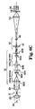
- FIG. 5 is a simplified diagram of a return arm 30 in accordance with one aspect of the present invention. Note that in the figures similar elements have retained their numbering for simplicity.
- Return arm 30 includes optical element 42 which is inserted into the light beam path between scanning optics 18 and pinhole lens 22.
- optical element 42 is a simple Keplerian telescope having an objective lens 46 and a low-power lens 44.
- the invention includes other optical elements such as a simple Galilean telescope and more complex multi-lens elements.
- Optical insert 42 acts as a telescope that magnifies the angle between the optic axis and light coming from an off-axis object.
- the spot at the pinhole plane is further away from the optical axis than in Figure 3 (Type II).
- Figure 3 Type II
- the spot at the pinhole plane is larger by the same factor as the increase in distance from the optical axis, resulting in no net improvement in resolution.
- a model may be developed for the system considering natural divergence of the beam.
- natural divergence of the beam is not a factor because either the beam is wide enough that the effect is minimized (the angular spread of the beam being inversely proportional to the beam diameter at its narrowest point), the beam path is sufficiently short that it is not noticeable, or by operating in what is called a finite-conjugate or Type I configuration.
- the beam leaving lenses 44,46 will be reduced in diameter such that divergence will be a factor. Not only is the beam angle to the optic axis magnified after passing through lenses 44,46 but the beam width is reduced.
- the present invention includes a physical optics model which accounts for beam divergence.
- ⁇ 4 ⁇ ⁇ d o
- ⁇ the wavelength of light
- d o the initial beam width.
- This equation describes divergence of a Gaussian beam. Note that the divergence described by Equation 1 is changed slightly because the beam profile is different and there usually is a small bit of phase curvature to the field as it leaves the second insert lens 46. These will modify the divergence angle and thus the beam width at the pinhole lens.
- FIG. 6A shows the positioning of relay lenses 80A and 80B in a typical embodiment of scanning optics 18.
- Lenses 80A,80B are positioned at the indicated distances relative to scanning mirror 82A, the objective lens 20, and each other.
- Scanning mirror 82A moves the beam as shown by the arrows in Figure 6A.
- Figure 6B shows an oblique view of a typical scanning system 18.
- Mirrors 82A, 82B each impart angular motion to the beam in orthogonal directions.
- Figure 6C shows the unfolded beam path along the return path and shows scanning optics 18 in greater detail.
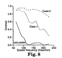
- FIG. 7 shows a schematic of a line profile across a portion of an image of a resolution target
- contrast (I MAX - I MIN ) / (I MAX + I MIN )
- the contrast between them and the background is 0.19.
- the Rayleigh resolution limit (or any other criterion) can be determined from these results.
- Contrast plots calculated from images obtained using device of Figure 6C are shown in Figures 8 and 9. As expected, the calculated "conventional confocal" model (i.e., prior art) provides the lowest resolution. The case with the insert in both the scanning optics and the detection arm is best.
- One aspect of the invention is the discovery that the natural divergence of the beam may be used advantageously to fill more of the pinhole lens 22 than in typical prior art systems. This results in a smaller focused spot in the pinhole plane.
- the desired optical divergence may be obtained by inserting or configuring appropriate optical elements anywhere in the optical path of return arm 30.
- One example is telescope 42 of Figure 5.
- Figure 6C Another example is shown in Figure 6C in which a 2:1 telescope is provided by lenses 80A,80B.
- Lenses 84A and 84B are also changed from a unit-magnification (1:1) element to a 2:1 telescope. This reduces the angular scan range at objective 20, which translates to a reduced scan area on object.
- each telescope reduces the width of the reflected beam as it passes back through the scanning optics 18 on return path 30.
- the return beam leaves the scanning optics, it has been reduced in width by a factor of 4.
- This beam is sufficiently narrow that it diverges in return path 30 and fills pinhole lens 22.
- light returning from a spot which is away from the center of the focused spot leaves mirror 82B at an angle to the optic axis which is four times greater than with 1:1 relay optics of the prior art.
- the contrast plots for this case are shown in Figures 8 and 9 as Case I.
- Figure 6C also shows a further enhancement in that telescope 42 is also provided in return arm 30. Telescope 42 narrows the beam even further and thereby results in stronger divergence and better filling of pinhole lens 22, and thus a smaller focused spot at pinhole 24. Further, telescope 42 magnifies the angle between light returning from a spot which is away from the center of the focused spot and the optical axis 34.
- the contrast plots for this case are shown in Figures 8 and 9 as Case II. Case II provides additional further improvement in the resolution in comparison to Case I.
- Figure 10 is provided to describe operation of the invention and illustrates the effect of the natural divergence in the return arm 40.
- the divergence of the on-axis spot is shown by the lines at 60.
- the divergence causes the beam to fill a larger portion of pinhole lens 22 than in prior art systems.
- Element 42 also provides the aforementioned increased deflection of off-axis light.
- the divergence should cause the beam to completely fill pinhole lens 22.
- Ux, Ux' are the scalar fields before and after a lens (or object or pinhole) at position x, respectively.
- Light is a propagating electromagnetic (vector) field, but a standard approximation for system design is to use a scalar field.
- fx, Px are the focal length and pupil size, respectively, of a lens at position x.
- the angular spectrum of plane waves is an exact description of the propagation of a field over all distance ranges for all degrees of beam divergence. Different levels of approximation of the ASPW description yield the known Fresnel and Fraunhoffer diffraction integrals.
- the shape of the light spot at pinhole 24 due to an on-axis point object can be calculated using the ASPW.
- the spot in the plane of pinhole 24 does not change shape as the point object is moved in the object plane.
- the position of the spot in the plane of pinhole 24 (as a function of the position of a point object in the object plane) can be predicted using standard geometric optics.
- the pupil of objective lens 20 is sufficiently large that for all reasonable values of d 20,44 , U 44 is effectively a plane wave.
- Equation 1 The equation describing the divergence angle ⁇ of a Gaussian beam is set forth above at Equation 1.
- d o is the width of the beam where it leaves lens 46.
- the beam profile is different, and there usually is a small bit of phase curvature to the field as it leaves lens 46. These will modify the divergence angle and thus the beam width at pinhole lens 22.
- U' 46 is sufficiently narrow that it diverges when propagating toward Pinhole lens 22.
- One design goal is that the beam diverge sufficiently such that the width of U 22 is close to the width of U' 20 . This can be done either by making U' 46 small (to increase the divergence angle) or by making d 46,22 large (to increase the available distance over which the beam can spread).
- U' 46 can be made small by having a large ratio f 44 /f 46 .
- Distance d 46,22 can be made large, but there are limits to how this can be done. Simple free space propagation from lens 46 to pinhole lens 22 is limited by the size of the instrument. Most commercial confocal microscopes are built as attachments on standard optical microscopes, and do not have room for the distances (on the order of a few meters) required. The beam can be folded into a more compact area by using mirrors. However, even the best mirrors introduce some wavefront distortion to the beam upon reflection (typically ⁇ /4). These errors accumulate and lead to a larger spot at the pinhole 24. This degrades the resolution of the instrument.
- Diffraction calculations for an on-axis object are used to determine the best focus position and the shape of the spot in the plane of pinhole 24, i.e., U 24 . Once the focus plane is found, the position of the spot (in the plane of pinhole 24) for an off-axis object can be calculated using geometric optics. Thus the lateral resolution can now be determined.
- Geometric optics predicts that for some conditions and combinations of lenses and distances, the spot will not move on pinhole 24 when the object is moved.
- the beam will be focused to a spot, and the beam will tilt about pinhole 24, but will not move laterally. This will degrade the response dramatically (to the point of non-confocal lateral response). This position can be predicted and avoided.
- the present invention includes insertion of at least one magnifying element in the return path of a confocal microscope to increase deflection of off-axis light.
- the optical element(s) of the insertion cause(s) the natural divergence of the beam to increase whereby a larger area of the pinhole lens is filled by the beam.
- the natural divergence refers to "physical optic" or “non-geometric" divergence of the beam in which the wavefront of the light diverges as the wavefront spreads out. Note that this is not the divergence which occurs with geometric optics which are not focused. Over a sufficiently long distance, the light beam will naturally diverge.
- the overall beam path can be as short as one or less meters.
- One aspect of the invention includes a confocal microscope with desired natural divergence and a beam path of less than 3 meters.
- any type of optical element may be inserted in the detection arm which provides this function and the invention is not limited to the telescope set forth in the preferred embodiment.
- suitable mirrors, prisms or active elements can be used to promote divergence and/or magnification.
- the microscope may be used as an ophthalmoscope in which the cornea plus lens of an eye of a patient acts as the objective lens for viewing the posterior of the eye.
- the microscope can be used in a system for retrieving optical data from a multilayer data medium of multiple layers of recorded optical data.
Landscapes
- Physics & Mathematics (AREA)
- Chemical & Material Sciences (AREA)
- Analytical Chemistry (AREA)
- General Physics & Mathematics (AREA)
- Optics & Photonics (AREA)
- Health & Medical Sciences (AREA)
- General Health & Medical Sciences (AREA)
- Ophthalmology & Optometry (AREA)
- Radiology & Medical Imaging (AREA)
- Surgery (AREA)
- Microscoopes, Condenser (AREA)
- Investigating, Analyzing Materials By Fluorescence Or Luminescence (AREA)
Claims (6)
- Microscope confocal à balayage pour former l'image d'un objet, comprenant :une source de lumière (12) fournissant un faisceau d'illumination dirigé le long d'un chemin optique comportant un axe optique (34) vers l'objet (8) ;un système de lentille objective (20) dans le chemin optique focalisant le faisceau d'illumination en un spot sur ou dans l'objet, en vertu de quoi l'objet émet un rayonnement depuis le spot, en fournissant ainsi un faisceau émanant du spot ;des composants optiques de balayage (18) dans le chemin optique afin de déplacer le spot focalisé en travers d'une surface de l'objet ;une lentille à sténopé (22) focalisant le faisceau émanant du spot vers un sténopé (24) dans le chemin optique ;le sténopé recevant au moins une partie du faisceau émanant du spot, lequel faisceau traverse le système de lentille objective (20) et les composants optiques de balayage (18) ;un détecteur (26) détectant le faisceau émanant du spot, lequel faisceau traverse le sténopé ; etau moins un télescope (42) dans le chemin optique placé entre la lentille à sténopé et les composants optiques de balayage pour réduire initialement le diamètre du faisceau émanant du spot focalisé sur l'axe, et collimaté par le système de lentille objective (20), ce qui augmentera la divergence optique naturelle et grossira tout angle hors d'axe du faisceau émanant du spot focalisé et de toute partie du faisceau issue d'un point hors d'axe.
- Microscope confocal à balayage selon la revendication 1, comprenant en outre au moins un télescope de relais comprenant des lentilles (80A, 80B) parmi les composants optiques de balayage (18).
- Microscope confocal à balayage selon les revendications 1 ou 2, comprenant en outre un télescope de relais comprenant des lentilles (84A) et (84B) parmi les composants optiques de balayage (18).
- Microscope confocal à balayage selon l'une quelconque des revendications 1 à 3, dans lequel des miroirs ou prismes sont insérés pour favoriser la divergence et le grossissement.
- Microscope confocal à balayage selon l'une quelconque des revendications 1 à 4, dans lequel la longueur totale du chemin optique est inférieure à trois mètres.
- Microscope confocal à balayage selon l'une quelconque des les revendications 1 à 5, dans lequel la source de lumière comprend un laser.
Applications Claiming Priority (3)
| Application Number | Priority Date | Filing Date | Title |
|---|---|---|---|
| US857127 | 1997-05-15 | ||
| US08/857,127 US6108127A (en) | 1997-05-15 | 1997-05-15 | High resolution confocal microscope |
| PCT/US1997/016855 WO1998052084A1 (fr) | 1997-05-15 | 1997-09-23 | Microscope confocal a haute resolution |
Publications (2)
| Publication Number | Publication Date |
|---|---|
| EP0981776A1 EP0981776A1 (fr) | 2000-03-01 |
| EP0981776B1 true EP0981776B1 (fr) | 2004-06-30 |
Family
ID=25325250
Family Applications (1)
| Application Number | Title | Priority Date | Filing Date |
|---|---|---|---|
| EP97943446A Expired - Lifetime EP0981776B1 (fr) | 1997-05-15 | 1997-09-23 | Microscope confocal a haute resolution |
Country Status (9)
| Country | Link |
|---|---|
| US (1) | US6108127A (fr) |
| EP (1) | EP0981776B1 (fr) |
| JP (1) | JP4054893B2 (fr) |
| KR (1) | KR20010012563A (fr) |
| AT (1) | ATE270439T1 (fr) |
| AU (1) | AU4491997A (fr) |
| CA (1) | CA2290575C (fr) |
| DE (1) | DE69729747T2 (fr) |
| WO (1) | WO1998052084A1 (fr) |
Cited By (1)
| Publication number | Priority date | Publication date | Assignee | Title |
|---|---|---|---|---|
| CN103054554A (zh) * | 2012-12-29 | 2013-04-24 | 陈英俊 | 一种沿轴向进行深度扫描的光学成像装置、方法及其应用 |
Families Citing this family (18)
| Publication number | Priority date | Publication date | Assignee | Title |
|---|---|---|---|---|
| AUPP548298A0 (en) * | 1998-08-27 | 1998-09-17 | Optiscan Pty Limited | Compact confocal endoscope and endomicroscope method and apparatus |
| GB9904150D0 (en) | 1999-02-23 | 1999-04-14 | Medical Res Council | Confocal microscope detector optics and methods for using them |
| GB2360162B (en) | 2000-01-07 | 2004-06-02 | Axon Instr Inc | Scanning microscope |
| JP4576664B2 (ja) * | 2000-03-08 | 2010-11-10 | 株式会社ニコン | 光路ズレ検知装置、および共焦点顕微鏡 |
| EP1164402B1 (fr) * | 2000-06-17 | 2010-04-28 | Leica Microsystems CMS GmbH | Microscope à balayage avec illumination multibande et élément optique pour un microscope à balayage avec illumination multibande |
| US6898367B2 (en) | 2000-06-17 | 2005-05-24 | Leica Microsystems Heidelberg Gmbh | Method and instrument for microscopy |
| DE20122783U1 (de) * | 2000-06-17 | 2007-11-15 | Leica Microsystems Cms Gmbh | Anordnung zum Untersuchen mikroskopischer Präparate mit einem Scanmikroskop und Beleuchtungseinrichtung für ein Scanmikroskop |
| DE10115590B4 (de) * | 2000-06-17 | 2020-11-05 | Leica Microsystems Cms Gmbh | Scanmikroskop |
| WO2002020729A2 (fr) * | 2000-09-06 | 2002-03-14 | UNIVERSITé LAVAL | Modele d'angiogenese humaine in vitro |
| DE10107210C1 (de) * | 2001-02-16 | 2002-10-10 | Evotec Ag | Mikroskop |
| DE10111824B4 (de) * | 2001-03-13 | 2017-04-06 | Leica Microsystems Cms Gmbh | Verfahren zum Justieren eines Mikroskops und Mikroskop mit Einrichtung zum Justieren des Lichtstrahls |
| DE102004053705B4 (de) * | 2004-11-03 | 2016-04-14 | Leica Microsystems Cms Gmbh | Detektionsvorrichtung für eine optische Anordnung und ein Konfokalmikroskop |
| WO2008081729A1 (fr) * | 2006-12-22 | 2008-07-10 | Nikon Corporation | Microscope confocal à balayage laser |
| KR100850214B1 (ko) * | 2007-05-23 | 2008-08-04 | 삼성전자주식회사 | 현미경 및 이를 이용한 이미지 데이터의 제공 방법. |
| US9007582B2 (en) * | 2013-03-15 | 2015-04-14 | University Of Rochester | Apparatus and method for suppression of background noise in microscopy imaging |
| CN106802479B (zh) * | 2017-03-22 | 2019-09-13 | 精微视达医疗科技(武汉)有限公司 | 激光扫描中继镜组及具有该中继镜组的共聚焦显微内窥镜 |
| KR102920182B1 (ko) * | 2022-11-21 | 2026-02-02 | 한국전자통신연구원 | 단일 픽셀 검출기로 작동 가능한 양자 이미징 장치 |
| US12535404B2 (en) | 2022-11-21 | 2026-01-27 | Electronics And Telecommunications Research Institute | Quantum imaging device capable of operating with single-pixel detectors |
Family Cites Families (9)
| Publication number | Priority date | Publication date | Assignee | Title |
|---|---|---|---|---|
| GB8531011D0 (en) * | 1985-12-17 | 1986-01-29 | Medical Res Council | Confocal scanning microscope |
| NL8701716A (nl) * | 1987-07-21 | 1989-02-16 | Philips Nv | Aftastende optische mikroskoop. |
| US5032720A (en) * | 1988-04-21 | 1991-07-16 | White John G | Confocal imaging system |
| US5153428A (en) * | 1990-06-15 | 1992-10-06 | Hamamatsu Photonics K.K. | Confocal laser scanning microscope having relay lens and a slit for removing stray light |
| GB9014263D0 (en) * | 1990-06-27 | 1990-08-15 | Dixon Arthur E | Apparatus and method for spatially- and spectrally- resolvedmeasurements |
| JP2801974B2 (ja) * | 1991-05-14 | 1998-09-21 | ローム株式会社 | 顕微鏡 |
| JP3082346B2 (ja) * | 1991-09-12 | 2000-08-28 | 株式会社ニコン | 蛍光コンフォーカル顕微鏡 |
| DE69231596T2 (de) * | 1991-10-31 | 2001-06-28 | Yokogawa Electric Corp Musashi | Konfokaler optischer Scanner |
| US5532873A (en) * | 1993-09-08 | 1996-07-02 | Dixon; Arthur E. | Scanning beam laser microscope with wide range of magnification |
-
1997
- 1997-05-15 US US08/857,127 patent/US6108127A/en not_active Expired - Fee Related
- 1997-09-23 JP JP54918898A patent/JP4054893B2/ja not_active Expired - Fee Related
- 1997-09-23 AU AU44919/97A patent/AU4491997A/en not_active Abandoned
- 1997-09-23 EP EP97943446A patent/EP0981776B1/fr not_active Expired - Lifetime
- 1997-09-23 DE DE69729747T patent/DE69729747T2/de not_active Expired - Fee Related
- 1997-09-23 AT AT97943446T patent/ATE270439T1/de not_active IP Right Cessation
- 1997-09-23 CA CA002290575A patent/CA2290575C/fr not_active Expired - Fee Related
- 1997-09-23 KR KR1019997010518A patent/KR20010012563A/ko not_active Ceased
- 1997-09-23 WO PCT/US1997/016855 patent/WO1998052084A1/fr not_active Ceased
Cited By (2)
| Publication number | Priority date | Publication date | Assignee | Title |
|---|---|---|---|---|
| CN103054554A (zh) * | 2012-12-29 | 2013-04-24 | 陈英俊 | 一种沿轴向进行深度扫描的光学成像装置、方法及其应用 |
| CN103054554B (zh) * | 2012-12-29 | 2014-10-22 | 陈英俊 | 一种沿轴向进行深度扫描的光学成像装置、方法及其应用 |
Also Published As
| Publication number | Publication date |
|---|---|
| AU4491997A (en) | 1998-12-08 |
| DE69729747D1 (de) | 2004-08-05 |
| ATE270439T1 (de) | 2004-07-15 |
| WO1998052084A1 (fr) | 1998-11-19 |
| CA2290575C (fr) | 2007-02-06 |
| JP2001525082A (ja) | 2001-12-04 |
| US6108127A (en) | 2000-08-22 |
| JP4054893B2 (ja) | 2008-03-05 |
| EP0981776A1 (fr) | 2000-03-01 |
| KR20010012563A (ko) | 2001-02-15 |
| CA2290575A1 (fr) | 1998-11-19 |
| DE69729747T2 (de) | 2005-07-21 |
Similar Documents
| Publication | Publication Date | Title |
|---|---|---|
| EP0981776B1 (fr) | Microscope confocal a haute resolution | |
| EP3125015B1 (fr) | Procédé et appareil de focalisation | |
| JP4047225B2 (ja) | 適応光学装置を有する顕微鏡、特にレーザ走査型顕微鏡 | |
| US6616279B1 (en) | Method and apparatus for measuring wavefront aberrations | |
| US5225671A (en) | Confocal optical apparatus | |
| US7550699B1 (en) | Removal of unwanted reflections in autofocus systems | |
| AU2001294623A1 (en) | Method and apparatus for measuring wavefront aberrations | |
| US7081994B2 (en) | Microscope for reflected-light and transmitted-light microscopy | |
| JPH11326860A (ja) | 波面変換素子及びそれを用いたレーザ走査装置 | |
| US5144477A (en) | Method of operating a scanning confocal imaging system | |
| US6680796B2 (en) | Microscope assemblage | |
| US6888680B2 (en) | Optical arrangement for obtaining information from a sample or an observed object | |
| EP3853651B1 (fr) | Microscope confocal à balayage laser conçu pour générer des foyers linéaires | |
| KR100519266B1 (ko) | 공초점 현미경 | |
| JP2000121945A (ja) | 集光装置 | |
| WO2000067060A1 (fr) | Procedes et appareil pour une resolution en profondeur amelioree en microscopie, au moyen d'informations hors foyer | |
| CA1329255C (fr) | Systeme d'imagerie a foyer commun |
Legal Events
| Date | Code | Title | Description |
|---|---|---|---|
| PUAI | Public reference made under article 153(3) epc to a published international application that has entered the european phase |
Free format text: ORIGINAL CODE: 0009012 |
|
| 17P | Request for examination filed |
Effective date: 19991207 |
|
| AK | Designated contracting states |
Kind code of ref document: A1 Designated state(s): AT CH DE GB LI |
|
| RBV | Designated contracting states (corrected) |
Designated state(s): AT CH DE GB LI |
|
| 17Q | First examination report despatched |
Effective date: 20020712 |
|
| GRAP | Despatch of communication of intention to grant a patent |
Free format text: ORIGINAL CODE: EPIDOSNIGR1 |
|
| GRAJ | Information related to disapproval of communication of intention to grant by the applicant or resumption of examination proceedings by the epo deleted |
Free format text: ORIGINAL CODE: EPIDOSDIGR1 |
|
| GRAP | Despatch of communication of intention to grant a patent |
Free format text: ORIGINAL CODE: EPIDOSNIGR1 |
|
| GRAS | Grant fee paid |
Free format text: ORIGINAL CODE: EPIDOSNIGR3 |
|
| GRAA | (expected) grant |
Free format text: ORIGINAL CODE: 0009210 |
|
| STAA | Information on the status of an ep patent application or granted ep patent |
Free format text: STATUS: THE PATENT HAS BEEN GRANTED |
|
| AK | Designated contracting states |
Kind code of ref document: B1 Designated state(s): AT CH DE GB LI |
|
| PG25 | Lapsed in a contracting state [announced via postgrant information from national office to epo] |
Ref country code: AT Free format text: LAPSE BECAUSE OF FAILURE TO SUBMIT A TRANSLATION OF THE DESCRIPTION OR TO PAY THE FEE WITHIN THE PRESCRIBED TIME-LIMIT Effective date: 20040630 |
|
| REG | Reference to a national code |
Ref country code: GB Ref legal event code: FG4D Ref country code: CH Ref legal event code: EP |
|
| REF | Corresponds to: |
Ref document number: 69729747 Country of ref document: DE Date of ref document: 20040805 Kind code of ref document: P |
|
| PLAQ | Examination of admissibility of opposition: information related to despatch of communication + time limit deleted |
Free format text: ORIGINAL CODE: EPIDOSDOPE2 |
|
| PLBQ | Unpublished change to opponent data |
Free format text: ORIGINAL CODE: EPIDOS OPPO |
|
| PLBI | Opposition filed |
Free format text: ORIGINAL CODE: 0009260 |
|
| 26 | Opposition filed |
Opponent name: LEICA MICROSYSTEMS AGCORPORATE PATENTS + TRADEMARK Effective date: 20050324 |
|
| PGFP | Annual fee paid to national office [announced via postgrant information from national office to epo] |
Ref country code: CH Payment date: 20070924 Year of fee payment: 11 |
|
| PGFP | Annual fee paid to national office [announced via postgrant information from national office to epo] |
Ref country code: GB Payment date: 20070926 Year of fee payment: 11 |
|
| PGFP | Annual fee paid to national office [announced via postgrant information from national office to epo] |
Ref country code: DE Payment date: 20071031 Year of fee payment: 11 |
|
| REG | Reference to a national code |
Ref country code: CH Ref legal event code: PL |
|
| GBPC | Gb: european patent ceased through non-payment of renewal fee |
Effective date: 20080923 |
|
| PG25 | Lapsed in a contracting state [announced via postgrant information from national office to epo] |
Ref country code: DE Free format text: LAPSE BECAUSE OF NON-PAYMENT OF DUE FEES Effective date: 20090401 |
|
| PG25 | Lapsed in a contracting state [announced via postgrant information from national office to epo] |
Ref country code: LI Free format text: LAPSE BECAUSE OF NON-PAYMENT OF DUE FEES Effective date: 20080930 Ref country code: CH Free format text: LAPSE BECAUSE OF NON-PAYMENT OF DUE FEES Effective date: 20080930 |
|
| PG25 | Lapsed in a contracting state [announced via postgrant information from national office to epo] |
Ref country code: GB Free format text: LAPSE BECAUSE OF NON-PAYMENT OF DUE FEES Effective date: 20080923 |