EP0981948A1 - Begrenzungsmauer, insbesondere für Beeteinfassungen, Frübeete, Abgrenzungen in Garten- und Grünanlagen oder dergleichen - Google Patents
Begrenzungsmauer, insbesondere für Beeteinfassungen, Frübeete, Abgrenzungen in Garten- und Grünanlagen oder dergleichen Download PDFInfo
- Publication number
- EP0981948A1 EP0981948A1 EP99890270A EP99890270A EP0981948A1 EP 0981948 A1 EP0981948 A1 EP 0981948A1 EP 99890270 A EP99890270 A EP 99890270A EP 99890270 A EP99890270 A EP 99890270A EP 0981948 A1 EP0981948 A1 EP 0981948A1
- Authority
- EP
- European Patent Office
- Prior art keywords
- components
- connecting elements
- boundary wall
- wall according
- coupling element
- Prior art date
- Legal status (The legal status is an assumption and is not a legal conclusion. Google has not performed a legal analysis and makes no representation as to the accuracy of the status listed.)
- Granted
Links
- 238000007688 edging Methods 0.000 title 1
- 230000008878 coupling Effects 0.000 claims description 68
- 238000010168 coupling process Methods 0.000 claims description 68
- 238000005859 coupling reaction Methods 0.000 claims description 68
- 230000000295 complement effect Effects 0.000 claims description 44
- 238000003780 insertion Methods 0.000 claims description 7
- 230000037431 insertion Effects 0.000 claims description 7
- 230000009194 climbing Effects 0.000 claims description 4
- 238000000465 moulding Methods 0.000 claims description 2
- 230000015572 biosynthetic process Effects 0.000 abstract 3
- 238000005755 formation reaction Methods 0.000 abstract 3
- 230000001154 acute effect Effects 0.000 description 3
- 239000003621 irrigation water Substances 0.000 description 2
- 238000004519 manufacturing process Methods 0.000 description 2
- 238000002347 injection Methods 0.000 description 1
- 239000007924 injection Substances 0.000 description 1
- 230000002262 irrigation Effects 0.000 description 1
- 238000003973 irrigation Methods 0.000 description 1
Images

Classifications
-
- E—FIXED CONSTRUCTIONS
- E01—CONSTRUCTION OF ROADS, RAILWAYS, OR BRIDGES
- E01C—CONSTRUCTION OF, OR SURFACES FOR, ROADS, SPORTS GROUNDS, OR THE LIKE; MACHINES OR AUXILIARY TOOLS FOR CONSTRUCTION OR REPAIR
- E01C11/00—Details of pavings
- E01C11/22—Gutters; Kerbs ; Surface drainage of streets, roads or like traffic areas
- E01C11/221—Kerbs or like edging members, e.g. flush kerbs, shoulder retaining means ; Joint members, connecting or load-transfer means specially for kerbs
- E01C11/222—Raised kerbs, e.g. for sidewalks ; Integrated or portable means for facilitating ascent or descent
-
- A—HUMAN NECESSITIES
- A01—AGRICULTURE; FORESTRY; ANIMAL HUSBANDRY; HUNTING; TRAPPING; FISHING
- A01G—HORTICULTURE; CULTIVATION OF VEGETABLES, FLOWERS, RICE, FRUIT, VINES, HOPS OR SEAWEED; FORESTRY; WATERING
- A01G9/00—Cultivation in receptacles, forcing-frames or greenhouses; Edging for beds, lawn or the like
- A01G9/28—Raised beds; Planting beds; Edging elements for beds, lawn or the like, e.g. tiles
Definitions
- the invention relates to a boundary wall, particularly for border borders, cold frames, boundaries in gardens and green areas or the like, with lined up and with each other connected, elongated components, each one, as a hollow profile open at the bottom trained base body with connecting elements molded onto the lateral end faces have.
- From CH 69 290 A is a bed border formed by standing concrete slabs uniaxial connection of adjacent components is known, in which complementary to each other trained and each forming a vertical sleeve end portions of the concrete slabs each other overlap and overlap one another by inserting them into the sleeves that are aligned Bolts are connected.
- US Pat. No. 4,869,018 A describes a bed border with a uniaxial connection of adjacent components known, which is designed as a irrigation water tank, the communicating with each other and each consists of vessels formed by a component.
- the same among themselves and each other with their end sections overlapping components are as except for lateral outlet openings for the irrigation water closed hollow body, the Irrigation water-absorbing cavities at the overlapping end sections of the components are each connected to one another in a liquid-tight manner by a hose coupling.
- EP 716 803 A1 describes a bed border with a uniaxial connection of adjacent components known, each of the same and with their upper and lower end portions mutually overlapping components is composed, each component being a has a hollow body that is open at the bottom, with one on the side An upper end section on the end face and a lower end section on the other lateral end face protrudes. At the upper end section is a vertical pin projecting downward from it as Fastener molded and the lower end portion contains a vertical sleeve as for Pin complementary connector. When lining up these components these are arranged with their upper and lower end sections overlapping one another and the mutually complementary connecting elements at the superimposed end sections two adjacent components inserted into each other, creating a uniaxial connection arises between the two adjacent components.
- the object of the invention is to eliminate the disadvantages mentioned.
- This training allows two lined up with their side faces and over one common coupling element interconnected components under any, pointed, arrange obtuse or right angles to one another, the coupling element, if necessary, can also be arranged at an angle or perpendicular to both components.
- the coupling element if necessary, can also be arranged at an angle or perpendicular to both components.
- the coupling elements with three or four complementary connecting elements can also be three or four components lined up with their side end faces, the side by side arranged connecting elements connected to each other via the coupling element are arranged at any angle to each other.
- the training according to the invention also facilitates the manufacture of the boundary wall, because the Components according to the desired course of the boundary wall on the ground can be put on and the components already sitting on the ground only when they are put on the coupling elements must be precisely aligned with each other, whereby Alignment errors caused by slight unevenness in the floor of those sitting on the ground Components can only be removed by placing the coupling elements.
- both the coupling elements and the components can be damaged be easily replaced, without at least several each, in the ground over more than theirs having to remove half of the recessed components of the boundary wall from the ground, to be able to solve the connection of two adjacent components, as is the case with the known ones Components with the cylindrical projections formed on the narrow end faces downward projecting connecting pin is required.
- Coupling element is provided with an elongated base body, the three in a row juxtaposed complementary connecting elements carries.
- Coupling element which has a base body with three T-shaped legs has, which each carry a complementary connecting element.
- This design allows for an existing boundary wall according to the invention with components connected in pairs by coupling elements a three components with each other create a stable connecting node without arranging the two already existing Modify components. All that is needed to form this node existing, only two complementary connecting elements having coupling element against a coupling element with three T-shaped arranged, each a complementary connecting element supporting legs to be replaced, which on the connecting elements of the two already existing components or on the connecting element of the added third component is placed.
- Coupling element which has a base body with three legs arranged in a star shape has, which each carry a complementary connecting element.
- Coupling element which has a base body with three T-shaped legs has that at the junction of the three legs and on each leg a complementary Connection element carries.
- Coupling element which has a base body with four legs arranged in a star shape has, which each carry a complementary connecting element.
- the coupling element with its basic body the space between the side faces of the with their with each other fills the same connecting elements abutting components.
- the coupling element is provided with an earth spike.
- At least one as a pin Complementary connecting element of the coupling element formed as a ground spike is.
- the coupling element its top with an insertion opening for roof brackets, climbing poles or the like is.
- the components on the Top are provided with an insertion opening for roof brackets, climbing poles or the like.
- the components according to the invention and the coupling elements according to the invention can be used as Injection molded parts made of plastic.
- Each Component 1, 2 has an elongated, essentially cuboid base body 4, which is designed as a hollow profile that is open at the bottom, and a molded one is formed on each of its lateral faces Connecting element 5 carries.
- the two connecting elements 5 of a component 1 or 2 are the same as each other.
- the coupling element 3 has a base body 6, the two juxtaposed, identical to each other and to the connecting elements 5 of the components 1, 2 carries complementary connecting elements 7. To connect the two, with their side Connecting elements 5 abutting components 1 and 2 becomes the coupling element 3 with its complementary connecting elements 7 from above onto the adjacent ones Connecting elements 5 of the two components 1, 2 pushed on.
- the connecting elements 5 of the components 1, 2 are in the illustrated embodiment as vertically extending sleeves and the complementary connecting elements 7 of the coupling element 3 as a plug which can be inserted into the sleeves from above, from the base body 6 of the coupling element 7 protrude downwards.
- the connecting elements 5 of the components 1, 2 as an upward-facing pin and the complementary connecting elements 7 of the Coupling element 3 as 6 integrated sleeves in the base body.
- insertion openings 8, 9 for roof brackets, climbing poles or earth spikes etc. may be provided.
- the insertion openings 8, 9 can be square or have a circular cross-section.
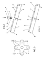
- Fig. 3 shows a star-shaped coupling element 10, the four arranged in a star shape Has leg 11, each carrying a complementary connecting element 12.
- Fig. 4 shows a coupling element 13 with a base body 14 which has two square on its top Has insertion openings 15 and on its underside two side by side, carries complementary connecting elements 16, which are designed as downwardly projecting pins, which are formed by flat wall sections arranged in a star shape.
- Fig. 5 shows a coupling element 17, in which one of the pegs each projecting downwards trained, complementary connecting elements 18 extended downwards and as a ground spike 19th is trained.
- FIGS. 6 and 7 show a section of a boundary wall according to the invention, the node is formed, on the three components abutting with their connecting elements 20, 21, 22 are stably connected to one another by means of a T-shaped coupling element 23.
- Two components 20, 21 are arranged along a straight line and meet with their integrally formed Connecting elements 20a and 21a directly to one another.
- the third component 22 is arranged transversely to the other two components 20, 21 and abuts with its molded Connecting element 22a laterally to the connecting elements 20a and 21a of the other two components 20, 21 on.
- the T-shaped coupling element 23 has a base body with three T-shaped arranged legs 24, 25, 26, each of which is designed as a downwardly projecting pin, wear complementary connecting element 27.
- the coupling element 23 For connecting the three components 20, 21, 22 the coupling element 23 from the position shown in FIG. 6 down to that shown in FIG. 7 Moved position, with its three complementary connecting elements designed as pins 27 into the connecting elements 20a, 21a, 22a of the three, each formed as sleeves Components 20, 21, 22 are inserted.
- Each of the three through the T-shaped coupling element 23 components 20, 21, 22 which are stably connected to one another can, if necessary, be used in his connecting element 20a, 21a, 22a inserted complementary connecting element 27 of the Coupling element 23 are pivoted, with acute angles between two adjacent Components can be realized.
- FIG. 8 shows a section of a boundary wall according to the invention, which is designed as a node on which three with their connecting elements 28a, 29a, each designed as sleeves, 30a abutting components 28, 29, 30 by a comb-shaped coupling element 31 be stably connected.
- Two components 28, 29 are arranged along a straight line and the third component 30 is arranged transversely thereto, with the integrally formed connecting element 30a of the third component 30 between the integrally formed connecting elements 28a and 29a of the other two components 28, 29.
- the comb-shaped coupling element 31 has three, complementary arranged in a row next to each other and each designed as a pin Connecting elements 32. These are on the connecting elements designed as sleeves 28a, 29a, 30a of the three components 28, 29, 30 aligned.
- the comb-shaped coupling element 31 with its three pins 32 in the sleeves 28a, 29a, 30a of the three components 28, 29, 30 used.
- the coupling elements according to the invention are designed so that the base body overlapping connecting elements of the components overlap.
- fills respective coupling element with its base body on the end faces of the abutting Components free space from, between the coupling element and the respective component only for placing the coupling element on the connecting element of the relevant component required play remains free.
- the lateral end faces of the components can be above the molded sleeves or above of the integrally formed lower end of the upwardly projecting pins.
Landscapes
- Engineering & Computer Science (AREA)
- Architecture (AREA)
- Civil Engineering (AREA)
- Structural Engineering (AREA)
- Life Sciences & Earth Sciences (AREA)
- Environmental Sciences (AREA)
- Cultivation Receptacles Or Flower-Pots, Or Pots For Seedlings (AREA)
- Joining Of Building Structures In Genera (AREA)
- Cultivation Of Plants (AREA)
- Road Paving Structures (AREA)
- Retaining Walls (AREA)
- Compounds Of Alkaline-Earth Elements, Aluminum Or Rare-Earth Metals (AREA)
Abstract
Description
Claims (15)
- Begrenzungsmauer, insbesonders für Beeteinfassungen, Frühbeete, Abgrenzungen in Garten- und Grünanlagen oder dergleichen, mit aneinandergereihten und untereinander verbundenen, langgestreckten Bauelementen (1, 2, 20, 21, 22, 28, 29, 30), die jeweils einen als nach unten offenes Hohlprofil ausgebildeten Grundkörper (4) mit an den seitlichen Stirnseiten angeformten Verbindungselementen (5, 20a, 21a, 22a, 28a, 29a, 30a) besitzen, dadurch gekennzeichnet, daß an beiden seitlichen Stirnseiten der Bauelemente (1, 2, 20, 21, 22, 28, 29, 30) untereinander gleiche Verbindungselemente (5, 20a, 21a, 22a, 28a, 29a, 30a) angeformt sind und daß die mit ihren seitlichen Stirnseiten aneinandergereihten Bauelemente (1, 2, 20, 21, 22, 28, 29, 30) untereinander jeweils durch ein Kupplungselement (3, 10, 13, 17, 23, 31) verbunden sind, das auf die einander benachbarten, seitlich nebeneinander angeordneten Verbindungselemente (5, 20a, 21a, 22a, 28a, 29a, 30a) der mit ihren seitlichen Stirnseiten aneinandergereihten Bauelemente (1, 2, 20, 21, 22, 28, 29, 30) von oben aufsetzbar ist und zu den Verbindungselementen (5, 20a, 21a, 22a, 28a, 29a, 30a) der Bauelemente (1, 2, 20, 21, 22, 28, 29, 30) komplementäre Verbindungselemente (7, 12, 16, 18, 27, 32) besitzt.
- Begrenzungsmauer nach Anspruch 1, dadurch gekennzeichnet, daß an den seitlichen Stirnseiten der Bauelemente (1, 2, 20, 21, 22, 28, 29, 30) sich im wesentlichen vertikal erstreckende Verbindungselemente (5, 20a, 21a, 22a, 28a, 29a, 30a) angeformt sind und die Kupplungselemente (3, 10, 13, 17, 23, 31) jeweils einen die seitlich nebeneinander angeordneten Verbindungselemente (5, 20a, 21a, 22a, 28a, 29a, 30a) aneinandergereihter Bauelemente (1, 2, 20, 21, 22, 28, 29, 30) überbrückenden Grundkörper (6, 11, 14, 24) besitzen, der die komplementären Verbindungselemente (7, 12, 16, 18, 27, 32) trägt.
- Begrenzungsmauer nach Anspruch 2, dadurch gekennzeichnet, daß zum Verbinden von Bauelementen (1, 2, 20, 21, 22, 28, 29, 30), bei denen die an ihren seitlichen Stirnseiten angeformten Verbindungselemente (5, 20a, 21a, 22a, 28a, 29a, 30a) als im wesentlichen vertikal verlaufende Hülsen ausgebildet sind, Kupplungselemente (3, 10, 13, 17, 23, 31) mit von ihrem Grundkörper (6, 11, 14, 24) nach unten abstehenden, komplementären Verbindungselementen (7, 12, 16, 18, 27, 32) vorgesehen sind, die als in die Hülsen von oben einsteckbare Zapfen ausgebildet sind.
- Begrenzungsmauer nach Anspruch 2, dadurch gekennzeichnet, daß zum Verbinden von Bauelementen, bei denen die an ihren seitlichen Stirnseiten angeformten Verbindungselemente als im wesentlichen vertikal verlaufende, mit ihrem freien Ende nach oben weisende Zapfen ausgebildet sind, Kupplungselemente mit in ihren Grundkörper integrierten, komplementären Verbindungselementen vorgesehen sind, die als auf die Zapfen von oben aufsteckbare Hülsen ausgebildet sind.
- Begrenzungsmauer nach einem der Ansprüche 1 bis 4, dadurch gekennzeichnet, daß zum Verbinden von drei, mit ihren untereinander gleichen Verbindungselementen (28a, 29a, 30a) aneinanderstoßenden Bauelementen (28, 29, 30) ein Kupplungselement (31) mit einem langgestreckten Grundkörper vorgesehen ist, der drei in einer Reihe nebeneinander angeordnete komplementäre (32) Verbindungselemente trägt.
- Begrenzungsmauer nach einem der Ansprüche 1 bis 4, dadurch gekennzeichnet, daß zum Verbinden von drei, mit ihren untereinander gleichen Verbindungselementen (20a, 21a, 22a) aneinanderstoßenden Bauelementen (20, 21, 22) ein Kupplungselement (23) vorgesehen ist, das einen Grundkörper mit drei T-förmig angeordneten Schenkeln (24, 25, 26) besitzt, die jeweils ein komplementäres Verbindungselement (27) tragen.
- Begrenzungsmauer nach einem der Ansprüche 1 bis 4, dadurch gekennzeichnet, daß zum Verbinden von drei mit ihren untereinander gleichen Verbindungselementen aneinanderstoßenden Bauelementen ein Kupplungselement vorgesehen ist, das einen Grundkörper mit drei sternförmig angeordneten Schenkeln besitzt, die jeweils ein komplementäres Verbindungselement tragen.
- Begrenzungsmauer nach einem der Ansprüche 1 bis 4, dadurch gekennzeichnet, daß zum Verbinden von vier mit ihren untereinander gleichen Verbindungselementen aneinanderstoßenden Bauelementen ein Kupplungselement vorgesehen ist, das einen Grundkörper mit drei T-förmig angeordneten Schenkeln besitzt, der an der Verbindungsstelle der drei Schenkel sowie an jedem Schenkel jeweils ein komplementäres Verbindungselement trägt.
- Begrenzungsmauer nach einem der Ansprüche 1 bis 4, dadurch gekennzeichnet, daß zum Verbinden von vier mit ihren untereinander gleichen Verbindungselementen aneinanderstoßenden Bauelementen ein Kupplungselement (10) vorgesehen ist, das einen Grundkörper mit vier sternförmig angeordneten Schenkeln (11) besitzt, die jeweils ein komplementäres Verbindungselement (12) tragen.
- Begrenzungsmauer nach einem der Ansprüche 1 bis 9, dadurch gekennzeichnet, daß das Kupplungselement (3, 10, 13, 17, 23, 31) mit seinem Grundkörper den Zwischenraum zwischen den seitlichen Stirnseiten der mit ihren untereinander gleichen Verbindungselementen (5, 20a, 21a, 22a, 28a, 29a, 30a) aneinanderstoßenden Bauelementen (1, 2, 20, 21, 22, 28, 29, 30) ausfüllt.
- Begrenzungsmauer nach einem der Ansprüche 1 bis 10, dadurch gekennzeichnet, daß das Kupplungselement mit einem Erdspieß versehen ist.
- Begrenzungsmauer nach Anspruch 11, dadurch gekennzeichnet, daß zumindest ein als Zapfen ausgebildetes komplementäres Verbindungselement (18) des Kupplungselementes (17) als Erdspieß (19) ausgebildet ist.
- Begrenzungsmauer nach einem der Ansprüche 1 bis 12, dadurch gekennzeichnet, daß das Kupplungselement (3, 10, 13, 17, 23, 31) an seiner Oberseite mit einer Einstecköffnung (9, 15) für Dachbügel, Rankstangen oder dergleichen versehen ist.
- Begrenzungsmauer nach einem der Ansprüche 1 bis 12, dadurch gekennzeichnet, daß die Bauelemente (1, 2) an der Oberseite mit einer Einstecköffnung (8) für Dachbügel, Rankstangen oder dergleichen versehen sind.
- Begrenzungsmauer nach einem der Ansprüche 1 bis 14, dadurch gekennzeichnet, daß bei den Bauelementen jeweils der an die Anformstelle des betreffenden Verbindungselementes nach oben anschließende Bereich der seitlichen Stirnseite eben ausgebildet ist.
Priority Applications (3)
| Application Number | Priority Date | Filing Date | Title |
|---|---|---|---|
| AT99890270T ATE270496T1 (de) | 1998-08-28 | 1999-08-23 | Begrenzungsmauer, insbesondere für beeteinfassungen, frübeete, abgrenzungen in garten- und grünanlagen oder dergleichen |
| SI9930669T SI0981948T1 (en) | 1998-08-28 | 1999-08-23 | Edging wall, especially for bed edges, spring beds, demarcation in garden and green places or the like |
| DK99890270T DK0981948T3 (da) | 1998-08-28 | 1999-08-23 | Afgrænsningskant, særligt til bedkanter, drivbænke, afgrænsninger i haveanlæg og grönne anlæg eller lignende |
Applications Claiming Priority (2)
| Application Number | Priority Date | Filing Date | Title |
|---|---|---|---|
| AT147398 | 1998-08-28 | ||
| AT0147398A AT406928B (de) | 1998-08-28 | 1998-08-28 | Begrenzungsmauer, insbesonders für beeteinfassungen, frühbeete, abgrenzungen in garten- und grünanlagen oder dergleichen |
Publications (2)
| Publication Number | Publication Date |
|---|---|
| EP0981948A1 true EP0981948A1 (de) | 2000-03-01 |
| EP0981948B1 EP0981948B1 (de) | 2004-07-07 |
Family
ID=3514672
Family Applications (1)
| Application Number | Title | Priority Date | Filing Date |
|---|---|---|---|
| EP99890270A Expired - Lifetime EP0981948B1 (de) | 1998-08-28 | 1999-08-23 | Begrenzungsmauer, insbesondere für Beeteinfassungen, Frübeete, Abgrenzungen in Garten- und Grünanlagen oder dergleichen |
Country Status (7)
| Country | Link |
|---|---|
| US (1) | US6389742B1 (de) |
| EP (1) | EP0981948B1 (de) |
| AT (2) | AT406928B (de) |
| DE (1) | DE59909891D1 (de) |
| DK (1) | DK0981948T3 (de) |
| ES (1) | ES2224594T3 (de) |
| SI (1) | SI0981948T1 (de) |
Cited By (2)
| Publication number | Priority date | Publication date | Assignee | Title |
|---|---|---|---|---|
| DE102005005240A1 (de) * | 2005-02-01 | 2006-08-10 | Manfred Miksch | Umrandung für Beete und Pflanzen |
| AT510960A4 (de) * | 2011-07-29 | 2012-08-15 | Wuester Heinrich | Begrenzungsmauer mit versteifungsvorrichtung |
Families Citing this family (17)
| Publication number | Priority date | Publication date | Assignee | Title |
|---|---|---|---|---|
| GB2337549B (en) * | 1998-05-19 | 2000-11-01 | Nigel Francis Maydew | Retaining components |
| IL148689A (en) * | 2002-03-14 | 2009-11-18 | Sagy Alexander | Collision partitions for roads and a method of assembling them |
| US7409796B2 (en) * | 2003-07-09 | 2008-08-12 | Rael Sacks | Extruded landscape edging strip and method of making same |
| US7322714B2 (en) * | 2005-06-08 | 2008-01-29 | Snapedge Canada Ltd. | Decorative light and landscape lighting system |
| US7478501B2 (en) * | 2005-09-02 | 2009-01-20 | Wilbanks Jr Robert | Modular interlocking plant support system |
| GB2467171A (en) * | 2009-01-27 | 2010-07-28 | Everedge Ltd | Edging for beds, lawns, or the like |
| US7966766B2 (en) * | 2009-03-24 | 2011-06-28 | Vogler Michael R | Raised garden bed kit |
| CN102605700B (zh) * | 2012-03-19 | 2015-04-08 | 李布尔 | 塑料路缘 |
| CN102696417A (zh) * | 2012-05-20 | 2012-10-03 | 张平 | 拼接式花盆组 |
| US9974240B1 (en) * | 2015-01-12 | 2018-05-22 | EZ Concepts LLC | Simulated stone landscape edging apparatus |
| CN106369028B (zh) | 2015-07-20 | 2021-06-04 | 锁栓公司 | 通道锁紧固件及紧固系统 |
| CN106369019B (zh) | 2015-07-20 | 2020-07-14 | 锁栓公司 | 夹锁紧固件和紧固系统 |
| USD792276S1 (en) | 2016-01-12 | 2017-07-18 | Ulysses C. Burnette | Planter |
| US10612207B1 (en) * | 2017-07-12 | 2020-04-07 | Robert B. Jordan, IV | Landscaping tie |
| USD842055S1 (en) * | 2017-08-16 | 2019-03-05 | Martin Baxter Payne | Raised bed garden panel |
| USD890017S1 (en) | 2018-12-11 | 2020-07-14 | Dalen Products, Inc. | Planter panel |
| US20250143231A1 (en) * | 2023-11-03 | 2025-05-08 | Ltr Products, Llc | Landscape edging system |
Citations (8)
| Publication number | Priority date | Publication date | Assignee | Title |
|---|---|---|---|---|
| CH69290A (de) | 1914-07-24 | 1915-06-01 | Beton Schleuderwerke A G Solot | Einfassung für Frühbeete, Graben etc. |
| US3343301A (en) * | 1964-11-23 | 1967-09-26 | Adelman Philip | Inclined planter and retaining wall construction |
| US4869018A (en) | 1987-04-13 | 1989-09-26 | Hjs Enterprises, Inc. | System forming a self-irrigating, raised bed |
| DE9107366U1 (de) | 1991-06-14 | 1991-10-02 | Betonwerk Lintel GmbH & Co. KG, 4840 Rheda-Wiedenbrück | Bauelement zur Sicherung von mit Erde verfüllten Pflanzbeeten |
| US5375369A (en) * | 1992-04-20 | 1994-12-27 | Verhoeve; Daniel L. | Landscape edgings with stakeable connectors |
| US5445362A (en) * | 1994-02-25 | 1995-08-29 | Reppert; Francis J. | Fence assembly |
| EP0716803A1 (de) | 1994-12-16 | 1996-06-19 | W. NEUDORFF GmbH KG | Bauteil zur Herstellung von Beeteinfassungen und Abgrenzungen in Gärten und Grünanlagen |
| DE29807973U1 (de) * | 1998-03-06 | 1998-08-27 | Wüster, Heinrich, Ing., Imst, Tirol | Mehrteilige Begrenzungsmauer, insbesondere für Frühbeete, sowie Frühbeet |
Family Cites Families (3)
| Publication number | Priority date | Publication date | Assignee | Title |
|---|---|---|---|---|
| US5283994A (en) * | 1992-06-19 | 1994-02-08 | Callison & Associates Xxi, Inc. | Landscape timber system |
| US5291708A (en) * | 1992-09-28 | 1994-03-08 | Packer Plastics, Incorporated | Modular framing system |
| US5442877A (en) * | 1994-04-06 | 1995-08-22 | Lindhal; John R. | Modular landscape borders |
-
1998
- 1998-08-28 AT AT0147398A patent/AT406928B/de not_active IP Right Cessation
-
1999
- 1999-08-23 EP EP99890270A patent/EP0981948B1/de not_active Expired - Lifetime
- 1999-08-23 ES ES99890270T patent/ES2224594T3/es not_active Expired - Lifetime
- 1999-08-23 SI SI9930669T patent/SI0981948T1/xx unknown
- 1999-08-23 AT AT99890270T patent/ATE270496T1/de not_active IP Right Cessation
- 1999-08-23 DE DE59909891T patent/DE59909891D1/de not_active Expired - Lifetime
- 1999-08-23 DK DK99890270T patent/DK0981948T3/da active
- 1999-08-27 US US09/384,766 patent/US6389742B1/en not_active Expired - Lifetime
Patent Citations (8)
| Publication number | Priority date | Publication date | Assignee | Title |
|---|---|---|---|---|
| CH69290A (de) | 1914-07-24 | 1915-06-01 | Beton Schleuderwerke A G Solot | Einfassung für Frühbeete, Graben etc. |
| US3343301A (en) * | 1964-11-23 | 1967-09-26 | Adelman Philip | Inclined planter and retaining wall construction |
| US4869018A (en) | 1987-04-13 | 1989-09-26 | Hjs Enterprises, Inc. | System forming a self-irrigating, raised bed |
| DE9107366U1 (de) | 1991-06-14 | 1991-10-02 | Betonwerk Lintel GmbH & Co. KG, 4840 Rheda-Wiedenbrück | Bauelement zur Sicherung von mit Erde verfüllten Pflanzbeeten |
| US5375369A (en) * | 1992-04-20 | 1994-12-27 | Verhoeve; Daniel L. | Landscape edgings with stakeable connectors |
| US5445362A (en) * | 1994-02-25 | 1995-08-29 | Reppert; Francis J. | Fence assembly |
| EP0716803A1 (de) | 1994-12-16 | 1996-06-19 | W. NEUDORFF GmbH KG | Bauteil zur Herstellung von Beeteinfassungen und Abgrenzungen in Gärten und Grünanlagen |
| DE29807973U1 (de) * | 1998-03-06 | 1998-08-27 | Wüster, Heinrich, Ing., Imst, Tirol | Mehrteilige Begrenzungsmauer, insbesondere für Frühbeete, sowie Frühbeet |
Cited By (3)
| Publication number | Priority date | Publication date | Assignee | Title |
|---|---|---|---|---|
| DE102005005240A1 (de) * | 2005-02-01 | 2006-08-10 | Manfred Miksch | Umrandung für Beete und Pflanzen |
| AT510960A4 (de) * | 2011-07-29 | 2012-08-15 | Wuester Heinrich | Begrenzungsmauer mit versteifungsvorrichtung |
| AT510960B1 (de) * | 2011-07-29 | 2012-08-15 | Wuester Heinrich | Begrenzungsmauer mit versteifungsvorrichtung |
Also Published As
| Publication number | Publication date |
|---|---|
| EP0981948B1 (de) | 2004-07-07 |
| ES2224594T3 (es) | 2005-03-01 |
| DK0981948T3 (da) | 2004-11-15 |
| ATA147398A (de) | 2000-03-15 |
| AT406928B (de) | 2000-10-25 |
| ATE270496T1 (de) | 2004-07-15 |
| DE59909891D1 (de) | 2004-08-12 |
| US6389742B1 (en) | 2002-05-21 |
| SI0981948T1 (en) | 2004-12-31 |
Similar Documents
| Publication | Publication Date | Title |
|---|---|---|
| AT406928B (de) | Begrenzungsmauer, insbesonders für beeteinfassungen, frühbeete, abgrenzungen in garten- und grünanlagen oder dergleichen | |
| DE4237188A1 (de) | ||
| DE2048551A1 (de) | Bauelement fur Wände, Gitter wände oder dergleichen | |
| EP0716803B1 (de) | Bauteil zur Herstellung von Beeteinfassungen und Abgrenzungen in Gärten und Grünanlagen | |
| DE2603018C3 (de) | Behälter für Pflanzen | |
| DE60211278T2 (de) | Modularer Zaun | |
| DE1811932A1 (de) | Betonbalken,insbesondere fuer Raumgitter und Stuetzmauern | |
| EP0616655A1 (de) | Bausatz aus beton-formsteinen sowie eine hieraus erstellte schwergewichts-stützmauer. | |
| DE19938848A1 (de) | Bausatz für eine Kugelrollbahn | |
| DE2325202A1 (de) | Bausatz fuer einen laufboden fuer campingzelte | |
| DE8800186U1 (de) | Bodenmarkierungselement | |
| DE3802738C2 (de) | Bauspielzeug | |
| AT2918U1 (de) | Begrenzungsmauer, insbesonders für beeteinfassungen, frühbeete, abgrenzungen in garten- und grünanlagen oder dergleichen | |
| DE29807973U1 (de) | Mehrteilige Begrenzungsmauer, insbesondere für Frühbeete, sowie Frühbeet | |
| DE2117499B2 (de) | ||
| DE29602675U1 (de) | Formstein zur Flächenbefestigung von Bodenflächen | |
| DE8704075U1 (de) | Rohrgestell | |
| EP0669424B1 (de) | Abstandshalter zum Festlegen der Fugenbreite | |
| EP1414124B1 (de) | Versorgungskanal zur Aufnahme von Wasser- und/oder Elektroleitungen für Aussenanlagen | |
| DE29515691U1 (de) | Verlegeelementeanordnung für befestigte Rasenflächen | |
| DE102020002383B3 (de) | Pflanzkübel | |
| CH586807A5 (en) | Nodal point connector for rod structures - has tubular holding socket and ring with seat for keyed linking plug | |
| DE4014935A1 (de) | Begruenbare laermschutzwand aus recycling-kunststoff | |
| DE20021030U1 (de) | Flächen-Einfassungs-System für gärtnerische Anlagen | |
| AT404491B (de) | Baukastenartig zusammensetzbare laufbretter in gärten |
Legal Events
| Date | Code | Title | Description |
|---|---|---|---|
| PUAI | Public reference made under article 153(3) epc to a published international application that has entered the european phase |
Free format text: ORIGINAL CODE: 0009012 |
|
| AK | Designated contracting states |
Kind code of ref document: A1 Designated state(s): AT BE CH CY DE DK ES FI FR GB GR IE IT LI LU MC NL PT SE |
|
| AX | Request for extension of the european patent |
Free format text: AL PAYMENT 19990827;LT PAYMENT 19990827;LV PAYMENT 19990827;MK PAYMENT 19990827;RO PAYMENT 19990827;SI PAYMENT 19990827 |
|
| 17P | Request for examination filed |
Effective date: 20000816 |
|
| AKX | Designation fees paid |
Free format text: AT BE CH CY DE DK ES FI FR GB GR IE IT LI LU MC NL PT SE |
|
| AXX | Extension fees paid |
Free format text: AL PAYMENT 19990827;LT PAYMENT 19990827;LV PAYMENT 19990827;MK PAYMENT 19990827;RO PAYMENT 19990827;SI PAYMENT 19990827 |
|
| 17Q | First examination report despatched |
Effective date: 20021107 |
|
| GRAP | Despatch of communication of intention to grant a patent |
Free format text: ORIGINAL CODE: EPIDOSNIGR1 |
|
| GRAS | Grant fee paid |
Free format text: ORIGINAL CODE: EPIDOSNIGR3 |
|
| GRAA | (expected) grant |
Free format text: ORIGINAL CODE: 0009210 |
|
| AK | Designated contracting states |
Kind code of ref document: B1 Designated state(s): AT BE CH CY DE DK ES FI FR GB GR IE IT LI LU MC NL PT SE |
|
| AX | Request for extension of the european patent |
Extension state: AL LT LV MK RO SI |
|
| PG25 | Lapsed in a contracting state [announced via postgrant information from national office to epo] |
Ref country code: IE Free format text: LAPSE BECAUSE OF FAILURE TO SUBMIT A TRANSLATION OF THE DESCRIPTION OR TO PAY THE FEE WITHIN THE PRESCRIBED TIME-LIMIT Effective date: 20040707 Ref country code: CY Free format text: LAPSE BECAUSE OF FAILURE TO SUBMIT A TRANSLATION OF THE DESCRIPTION OR TO PAY THE FEE WITHIN THE PRESCRIBED TIME-LIMIT Effective date: 20040707 |
|
| REG | Reference to a national code |
Ref country code: GB Ref legal event code: FG4D Free format text: NOT ENGLISH |
|
| REG | Reference to a national code |
Ref country code: CH Ref legal event code: EP |
|
| REG | Reference to a national code |
Ref country code: IE Ref legal event code: FG4D Free format text: GERMAN |
|
| REF | Corresponds to: |
Ref document number: 59909891 Country of ref document: DE Date of ref document: 20040812 Kind code of ref document: P |
|
| PG25 | Lapsed in a contracting state [announced via postgrant information from national office to epo] |
Ref country code: LU Free format text: LAPSE BECAUSE OF NON-PAYMENT OF DUE FEES Effective date: 20040823 Ref country code: AT Free format text: LAPSE BECAUSE OF NON-PAYMENT OF DUE FEES Effective date: 20040823 |
|
| PG25 | Lapsed in a contracting state [announced via postgrant information from national office to epo] |
Ref country code: MC Free format text: LAPSE BECAUSE OF NON-PAYMENT OF DUE FEES Effective date: 20040831 |
|
| REG | Reference to a national code |
Ref country code: CH Ref legal event code: NV Representative=s name: RITSCHER & PARTNER AG |
|
| PG25 | Lapsed in a contracting state [announced via postgrant information from national office to epo] |
Ref country code: SE Free format text: LAPSE BECAUSE OF FAILURE TO SUBMIT A TRANSLATION OF THE DESCRIPTION OR TO PAY THE FEE WITHIN THE PRESCRIBED TIME-LIMIT Effective date: 20041007 Ref country code: GR Free format text: LAPSE BECAUSE OF FAILURE TO SUBMIT A TRANSLATION OF THE DESCRIPTION OR TO PAY THE FEE WITHIN THE PRESCRIBED TIME-LIMIT Effective date: 20041007 |
|
| GBT | Gb: translation of ep patent filed (gb section 77(6)(a)/1977) | ||
| REG | Reference to a national code |
Ref country code: DK Ref legal event code: T3 |
|
| LTIE | Lt: invalidation of european patent or patent extension |
Effective date: 20040707 |
|
| REG | Reference to a national code |
Ref country code: SI Ref legal event code: IF |
|
| REG | Reference to a national code |
Ref country code: ES Ref legal event code: FG2A Ref document number: 2224594 Country of ref document: ES Kind code of ref document: T3 |
|
| REG | Reference to a national code |
Ref country code: IE Ref legal event code: FD4D |
|
| ET | Fr: translation filed | ||
| PLBE | No opposition filed within time limit |
Free format text: ORIGINAL CODE: 0009261 |
|
| STAA | Information on the status of an ep patent application or granted ep patent |
Free format text: STATUS: NO OPPOSITION FILED WITHIN TIME LIMIT |
|
| 26N | No opposition filed |
Effective date: 20050408 |
|
| PG25 | Lapsed in a contracting state [announced via postgrant information from national office to epo] |
Ref country code: PT Free format text: LAPSE BECAUSE OF NON-PAYMENT OF DUE FEES Effective date: 20041207 |
|
| REG | Reference to a national code |
Ref country code: CH Ref legal event code: PCAR Free format text: RITSCHER & PARTNER AG;RESIRAIN 1;8125 ZOLLIKERBERG (CH) |
|
| PGFP | Annual fee paid to national office [announced via postgrant information from national office to epo] |
Ref country code: NL Payment date: 20120814 Year of fee payment: 14 |
|
| PGFP | Annual fee paid to national office [announced via postgrant information from national office to epo] |
Ref country code: ES Payment date: 20130829 Year of fee payment: 15 Ref country code: DK Payment date: 20130821 Year of fee payment: 15 Ref country code: FI Payment date: 20130813 Year of fee payment: 15 |
|
| PGFP | Annual fee paid to national office [announced via postgrant information from national office to epo] |
Ref country code: GB Payment date: 20130821 Year of fee payment: 15 |
|
| REG | Reference to a national code |
Ref country code: CH Ref legal event code: PFA Owner name: WUESTER, HEINRICH, AT Free format text: FORMER OWNER: WUESTER, HEINRICH, AT |
|
| PGFP | Annual fee paid to national office [announced via postgrant information from national office to epo] |
Ref country code: BE Payment date: 20130823 Year of fee payment: 15 |
|
| REG | Reference to a national code |
Ref country code: NL Ref legal event code: V1 Effective date: 20140301 |
|
| PG25 | Lapsed in a contracting state [announced via postgrant information from national office to epo] |
Ref country code: NL Free format text: LAPSE BECAUSE OF NON-PAYMENT OF DUE FEES Effective date: 20140301 |
|
| PGFP | Annual fee paid to national office [announced via postgrant information from national office to epo] |
Ref country code: IT Payment date: 20140829 Year of fee payment: 16 |
|
| REG | Reference to a national code |
Ref country code: DK Ref legal event code: EBP Effective date: 20140831 |
|
| GBPC | Gb: european patent ceased through non-payment of renewal fee |
Effective date: 20140823 |
|
| PG25 | Lapsed in a contracting state [announced via postgrant information from national office to epo] |
Ref country code: FI Free format text: LAPSE BECAUSE OF NON-PAYMENT OF DUE FEES Effective date: 20140823 Ref country code: BE Free format text: LAPSE BECAUSE OF NON-PAYMENT OF DUE FEES Effective date: 20140831 |
|
| REG | Reference to a national code |
Ref country code: SI Ref legal event code: KO00 Effective date: 20150408 |
|
| PG25 | Lapsed in a contracting state [announced via postgrant information from national office to epo] |
Ref country code: DK Free format text: LAPSE BECAUSE OF NON-PAYMENT OF DUE FEES Effective date: 20140831 Ref country code: GB Free format text: LAPSE BECAUSE OF NON-PAYMENT OF DUE FEES Effective date: 20140823 |
|
| REG | Reference to a national code |
Ref country code: ES Ref legal event code: FD2A Effective date: 20160201 |
|
| PG25 | Lapsed in a contracting state [announced via postgrant information from national office to epo] |
Ref country code: IT Free format text: LAPSE BECAUSE OF NON-PAYMENT OF DUE FEES Effective date: 20150823 Ref country code: ES Free format text: LAPSE BECAUSE OF NON-PAYMENT OF DUE FEES Effective date: 20140824 |
|
| REG | Reference to a national code |
Ref country code: FR Ref legal event code: PLFP Year of fee payment: 18 |
|
| REG | Reference to a national code |
Ref country code: FR Ref legal event code: PLFP Year of fee payment: 19 |
|
| PGFP | Annual fee paid to national office [announced via postgrant information from national office to epo] |
Ref country code: FR Payment date: 20170822 Year of fee payment: 19 |
|
| REG | Reference to a national code |
Ref country code: DE Ref legal event code: R079 Ref document number: 59909891 Country of ref document: DE Free format text: PREVIOUS MAIN CLASS: A01G0001080000 Ipc: A01G0009280000 |
|
| PGFP | Annual fee paid to national office [announced via postgrant information from national office to epo] |
Ref country code: DE Payment date: 20180731 Year of fee payment: 20 |
|
| PGFP | Annual fee paid to national office [announced via postgrant information from national office to epo] |
Ref country code: CH Payment date: 20180802 Year of fee payment: 20 |
|
| REG | Reference to a national code |
Ref country code: DE Ref legal event code: R071 Ref document number: 59909891 Country of ref document: DE |
|
| PG25 | Lapsed in a contracting state [announced via postgrant information from national office to epo] |
Ref country code: FR Free format text: LAPSE BECAUSE OF NON-PAYMENT OF DUE FEES Effective date: 20180831 |
|
| REG | Reference to a national code |
Ref country code: CH Ref legal event code: PL |