EP0981978A1 - Meuble de rangement à géométrie variable - Google Patents
Meuble de rangement à géométrie variable Download PDFInfo
- Publication number
- EP0981978A1 EP0981978A1 EP98202862A EP98202862A EP0981978A1 EP 0981978 A1 EP0981978 A1 EP 0981978A1 EP 98202862 A EP98202862 A EP 98202862A EP 98202862 A EP98202862 A EP 98202862A EP 0981978 A1 EP0981978 A1 EP 0981978A1
- Authority
- EP
- European Patent Office
- Prior art keywords
- plate
- upper plate
- storage unit
- variable geometry
- feet
- Prior art date
- Legal status (The legal status is an assumption and is not a legal conclusion. Google has not performed a legal analysis and makes no representation as to the accuracy of the status listed.)
- Withdrawn
Links
Images



Classifications
-
- A—HUMAN NECESSITIES
- A47—FURNITURE; DOMESTIC ARTICLES OR APPLIANCES; COFFEE MILLS; SPICE MILLS; SUCTION CLEANERS IN GENERAL
- A47B—TABLES; DESKS; OFFICE FURNITURE; CABINETS; DRAWERS; GENERAL DETAILS OF FURNITURE
- A47B11/00—Tables with tops revolvable on vertical spindles
Definitions
- the invention relates to a new storage unit with variable geometry. More specifically, it relates to a table comprising cavities capable of serving as storage place.
- the object of the invention is to overcome these drawbacks, by proposing a storage table simple to make, easy to use, and allowing free access to one or more storage areas without requiring significant movement of the switchboard upper part of the table.
- This variable geometry storage unit has a top shelf forming a table and a base comprising at least one cavity capable of serving storage area, said tray being pivotally mounted in a horizontal plane by report to said base in order to free access to the cavity (ies).
- This piece of furniture is characterized in that the base includes four legs distributed to the four vertices of a square and interconnected by means of at least one tray intermediate receiving the pivot ensuring the pivoting of the upper plate with respect to said base, and in that said upper plate has at least one cutout at its periphery, so that said cutout releases the end upper of one of the four feet (2) by rotation of the upper plate (1).
- the number of cuts can be two or even four, and in this case, distributed so that said cutouts simultaneously release the upper end of the four legs by rotation of 45 ° of the upper plate with respect to an origin position where said ends are totally closed by said plate.
- each of the legs is square, and the cutout (s) are of corresponding shape, in order to completely free access to the upper end of the feet.
- the cross section of the legs is arbitrary, and the cutout (s) are corresponding shape.
- the cabinet comprises means for blocking the upper plate respectively in position closing the upper ends of the feet and freeing access to said extremities.
- the table according to the invention firstly comprises an upper plate (1), of square shape, constituting the table itself.
- This upper plate (1) rests on a base (2) by means of a pivot (5), itself resting on a plate intermediate (3).
- This intermediate plate (3) parallel to the plate (1), connects the four feet (2) constituting the base, in the vicinity of their upper end.
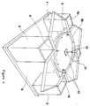
- These four feet have a horizontal cross section of square shape, and are hollowed out, as well as can be seen in FIG. 1.
- These recesses (10) constitute as many zones storage.
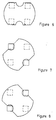
- the four feet (2) are regularly distributed to the four vertices of a square (see Figures 2 and 3).
- the upper plate (1) is capable of pivoting, by placing in place of a pivot (5), relative to the intermediate plate (3), integral with the base (2), and therefore fixed.
- the angular displacement of said upper plate (1) is limited to 45 °, as can be seen very clearly in Figures 2 and 3.
- This angular movement is limited at its two ends by the cooperation of a metal stop (6), integral of said upper plate (1), and fixed under its lower surface, with two latches magnetic (7) and (8), integral with the intermediate plate (3), and fixed on its surface greater than 45 ° from each other relative to the center of said plate (3).
- these blocking means are consisting on the one hand of ball latches (14, 17), mounted on the upper face of the lower plate (3), and on the other hand, sockets (13), arranged so additional in number and positioning on the internal face of the upper plate (1).
- the balls (17) cooperate with the sockets (13) when one is in the locking position.
- the number of latch-socket pairs is increased, when we wishes to harden the blocking and vice versa.
- the pivot consists for example of a plate (11), secured in particular by screwing, to the internal face of the upper plate (1).
- This plate has in its center a hollow tube (12), the lower end of which is tapped. This tube crosses the plateau lower (3) through a through hole.
- a screw (15) is screwed into said hollow tube, after have itself passed through a spring strip (16), so as to press this leaf spring against the internal face of the lower plate (3).
- an annular friction strip (18) for example made of PTFE, and secured to the upper face of the lower plate (3). This band of friction also makes it possible to obtain a certain clearance between the two plates (1, 3), optimizing the operation of the locking means.
- the upper plate (1) has four cutouts (4), made at the periphery of said tray, and centered at each side of the tray (1), itself shaped square. Furthermore, these cutouts are in the form of a half-square, the diagonal of said square extending the edge of the side considered of the plate. In addition, the dimensions of these cutouts are such that, according to one of the extreme rotation positions of the upper plate (1), hereinafter referred to as temporarily open position ⁇ , the cutouts (4) are located simultaneously at plumb with the feet (2) and therefore with the cavities (10), as shown in FIGS. 1 and 3, that is to say that they completely free access to said cavities.
- the two extreme positions of rotation of the upper plate (1) are defined by the positioning of the magnetic latches (7, 8) at the level of the intermediate plate (3), when such means are used.
- the cross section of the feet (2) is square, and that the cutouts (4) adopt an appropriate corresponding shape.
- the invention cannot be limited to this single form, and that circular, polygonal, etc. sections could just as easily be used, the cutouts made within the upper plate then adopting a corresponding shape, so as in the example described, to be able to completely free access to the cavities provided in the feet during the rotation of said upper plate in the open position.
- the four feet (2) can be connected to the base by a base (9) or a shelf.
- the upper plate (1) is provided with only two cutouts, arranged in opposite directions. It is thus observed that by rotation of 45 ° of said plate relative to an origin position for which the upper end of each of the feet is closed, we release everything first access to the upper end of two feet, then by another rotation of 45 °, we close these upper ends, then by a new rotation of 45 °, we release access to the upper end of the other two feet. It is therefore possible to have a rectangular top tray, but also any other shape, such as that in particular oval, etc.
Landscapes
- Tables And Desks Characterized By Structural Shape (AREA)
- Drawers Of Furniture (AREA)
Abstract
Description
Claims (10)
- Meuble de rangement à géométrie variable comportant un plateau supérieur (1) formant table et un piétement (2) comprenant au moins une cavité (10) susceptible de faire office de zone de rangement, ledit plateau (1) étant monté pivotant dans un plan horizontal par rapport audit piétement (2) afin de libérer l'accès à la (aux) cavité(s) (10), caractérisé en ce que le piétement (2) comprend quatre pieds répartis aux quatre sommets d'un carré et reliés entre eux au moyen d'au moins un plateau intermédiaire (3) recevant un pivot (5) permettant d'assurer le pivotement du plateau supérieur (1) par rapport audit piétement (2), et en ce que ledit plateau supérieur (1) présente au moins une découpe (4) ménagée à sa périphérie, de telle sorte que ladite découpe (4) libère l'extrémité supérieure de l'un des quatre pieds (2) par rotation du plateau supérieur (1).
- Meuble de rangement à géométrie variable selon la revendication 1, caractérisé en ce que le plateau supérieur présente deux découpes réparties de manière opposée, de telle sorte qu'une rotation dudit plateau supérieur (1) par rapport à une position origine où lesdites extrémités sont totalement obturées par ledit plateau (1) libère simultanément l'extrémité supérieure de deux des quatre pieds (2) tout en maintenant obturée celle des deux autres pieds.
- Meuble de rangement à géométrie variable selon la revendication 1, caractérisé en ce que le plateau supérieur (1) présente quatre découpes (4) ménagées à sa périphérie et positionnées à 90° consécutivement l'une de l'autre, de telle sorte que lesdites découpes (4) libèrent simultanément l'extrémité supérieure des quatre pieds (2) par rotation de 45° du plateau supérieur par rapport à une position origine où lesdites extrémités sont toutes totalement obturées par ledit plateau.
- Meuble de rangement à géométrie variable selon l'une des revendications 1 à 3, caractérisé en ce que la section transversale de chacun des pieds (2) est de forme carrée, et en ce que la ou les découpes (4) ménagées au niveau du plateau supérieur (1) sont de forme correspondante, afin de libérer totalement l'accès à l'extrémité supérieure des pieds (2) lorsque ledit plateau (1) est en 〈〈position ouverte〉〉.
- Meuble de rangement à géométrie variable selon l'une des revendications 1 à 3, caractérisé en ce que la section transversale des pieds (2) est quelconque, et en ce que la ou les découpes (4) ménagées au niveau du plateau supérieur (1) sont de forme correspondante, afin de libérer totalement l'accès à l'extrémité supérieure des pieds (2) lorsque ledit plateau (1) est en 〈〈position ouverte〉〉.
- Meuble de rangement à géométrie variable selon l'une des revendications 1 à 5, caractérisé en ce qu'il comporte des moyens de blocage du plateau supérieur (1) respectivement en position fermée, obturant les extrémités supérieures des pieds (2), et ouverte, libérant l'accès auxdites extrémités.
- Meuble de rangement à géométrie variable selon la revendication 6, caractérisé en ce que les moyens de blocage sont constitués respectivement d'une butée métallique (6), solidaire dudit plateau supérieur(1), et fixée sous sa surface inférieure, destinée à coopérer avec deux loqueteaux magnétiques (7) et (8), solidaires du plateau intermédiaire (3), et fixés sur sa surface supérieure à 45° l'un de l'autre par rapport au centre dudit plateau (3).
- Meuble de rangement à géométrie variable selon la revendication 6, caractérisé en ce que les moyens de blocage sont constitués respectivement par des loqueteaux à billes, dont le nombre varie en fonction de la dureté du blocage souhaitée, montés sur le plateau inférieur (3), et par des douilles en nombre égal et positionnées de manière complémentaire sur la face interne du plateau (1), afin de recevoir simultanément l'extrémité supérieure desdites billes.
- Meuble de rangement à géométrie variable selon l'une des revendications 1 à 8, caractérisé en ce que le plateau inférieur (3) reçoit une bande de frottement annulaire, destinée à coopérer avec le plateau supérieur (1).
- Meuble de rangement à géométrie variable selon la revendication 9, caractérisé en ce que le pivot permettant la rotation du plateau supérieur (1) par rapport au plateau inférieur (3) est constitué par une platine perforée solidarisée sur la face interne du plateau supérieur (1), et se prolongeant par un tube creux taraudé vertical traversant le plateau inférieur (3), avec lequel il coopère par l'intermédiaire d'une vis venant se visser dans le tube taraudé, venant corollairement plaquer une lame ressort contre la face interne dudit plateau inférieur (3), de telle sorte à maintenir plaqué le plateau supérieur (1) sur le plateau inférieur (3) au niveau de la bande de frottement.
Priority Applications (2)
| Application Number | Priority Date | Filing Date | Title |
|---|---|---|---|
| FR9705689A FR2762765B1 (fr) | 1997-04-30 | 1997-04-30 | Meuble de rangement a geometrie variable |
| EP98202862A EP0981978A1 (fr) | 1997-04-30 | 1998-08-27 | Meuble de rangement à géométrie variable |
Applications Claiming Priority (2)
| Application Number | Priority Date | Filing Date | Title |
|---|---|---|---|
| FR9705689A FR2762765B1 (fr) | 1997-04-30 | 1997-04-30 | Meuble de rangement a geometrie variable |
| EP98202862A EP0981978A1 (fr) | 1997-04-30 | 1998-08-27 | Meuble de rangement à géométrie variable |
Publications (1)
| Publication Number | Publication Date |
|---|---|
| EP0981978A1 true EP0981978A1 (fr) | 2000-03-01 |
Family
ID=26150650
Family Applications (1)
| Application Number | Title | Priority Date | Filing Date |
|---|---|---|---|
| EP98202862A Withdrawn EP0981978A1 (fr) | 1997-04-30 | 1998-08-27 | Meuble de rangement à géométrie variable |
Country Status (2)
| Country | Link |
|---|---|
| EP (1) | EP0981978A1 (fr) |
| FR (1) | FR2762765B1 (fr) |
Citations (1)
| Publication number | Priority date | Publication date | Assignee | Title |
|---|---|---|---|---|
| FR2696625A1 (fr) * | 1992-10-14 | 1994-04-15 | Dassis Daniel | Meuble à géométrie variable. |
-
1997
- 1997-04-30 FR FR9705689A patent/FR2762765B1/fr not_active Expired - Fee Related
-
1998
- 1998-08-27 EP EP98202862A patent/EP0981978A1/fr not_active Withdrawn
Patent Citations (1)
| Publication number | Priority date | Publication date | Assignee | Title |
|---|---|---|---|---|
| FR2696625A1 (fr) * | 1992-10-14 | 1994-04-15 | Dassis Daniel | Meuble à géométrie variable. |
Also Published As
| Publication number | Publication date |
|---|---|
| FR2762765A1 (fr) | 1998-11-06 |
| FR2762765B1 (fr) | 1999-08-13 |
Similar Documents
| Publication | Publication Date | Title |
|---|---|---|
| FR3067576B1 (fr) | Boitier pour produit cosmetique | |
| FR2511942A1 (fr) | Support de poignet pour une machine de bureau a clavier | |
| EP0966233B1 (fr) | Bague pour dispositif d'osteosynthese a angulation, et dispositif d'osteosynthese l'incorporant | |
| CA2018707C (fr) | Coffret a fermeture rapide | |
| FR2930124A1 (fr) | Meuble demontable | |
| FR2729248A1 (fr) | Boitier pour disque compact notamment | |
| FR3069143A1 (fr) | Un plateau support d'un outil pour appareil de preparation culinaire et appareil de preparation culinaire le comportant | |
| FR2833111A1 (fr) | Socle de prise de courant a obturateur d'alveoles et gamme comprenant un tel socle | |
| FR2762765A1 (fr) | Meuble de rangement a geometrie variable | |
| FR2883153A1 (fr) | Dispositif de prehension pivotant pour un ustensile culinaire | |
| FR3023866A1 (fr) | "charniere" | |
| FR2775180A1 (fr) | Perfectionnement aux paniers de lave-vaisselle a clayettes | |
| FR2712164A3 (fr) | Friteuse à air pulsé. | |
| FR2866792A1 (fr) | Table a plateau basculant et amovible | |
| FR2807924A1 (fr) | Systeme de reglage vertical d'un support sur un montant et son utilisation pour la realisation d'etageres | |
| WO2005070264A1 (fr) | Dispositif adapte pour la presentation d’une gamme d’objets | |
| BE1013142A5 (fr) | Systeme de fixation ajustable sur des profiles. | |
| FR2677084A1 (fr) | Dispositif d'assemblage pour profiles creux. | |
| FR2466965A1 (fr) | Pietement pour meubles pivotants | |
| FR2469894A1 (fr) | Lit basculant | |
| FR2616052A1 (fr) | Principe de pliage de pietement pour mobilier | |
| FR2921048A1 (fr) | Organe de calage d'un appareil de cuisson comportant une cuve et un couvercle et emballage comprenant un tel organe | |
| FR2751681A1 (fr) | Dispositif formant pied et poteau support pour cloison mobile | |
| EP0785738B1 (fr) | Pietement rigide pour bureau a plateau reversible | |
| FR3031161A1 (fr) | Tablette pour porter des objets au-dessus d'un support de type ecran de television ou d'ordinateur |
Legal Events
| Date | Code | Title | Description |
|---|---|---|---|
| PUAI | Public reference made under article 153(3) epc to a published international application that has entered the european phase |
Free format text: ORIGINAL CODE: 0009012 |
|
| AK | Designated contracting states |
Kind code of ref document: A1 Designated state(s): DE GB |
|
| AX | Request for extension of the european patent |
Free format text: AL;LT;LV;MK;RO;SI |
|
| K1C3 | Correction of patent application (complete document) published |
Effective date: 20000301 |
|
| RTI1 | Title (correction) |
Free format text: STOW AWAY FURNITURE WITH SCALABLE GEOMETRY |
|
| 17P | Request for examination filed |
Effective date: 20000724 |
|
| AKX | Designation fees paid |
Free format text: DE GB |
|
| 17Q | First examination report despatched |
Effective date: 20021018 |
|
| STAA | Information on the status of an ep patent application or granted ep patent |
Free format text: STATUS: THE APPLICATION IS DEEMED TO BE WITHDRAWN |
|
| 18D | Application deemed to be withdrawn |
Effective date: 20030301 |