EP0981996B1 - Bildkorrektur für ein geneigtes Gehäuse in einem Mehrschicht-Computertomograph - Google Patents
Bildkorrektur für ein geneigtes Gehäuse in einem Mehrschicht-Computertomograph Download PDFInfo
- Publication number
- EP0981996B1 EP0981996B1 EP99306600A EP99306600A EP0981996B1 EP 0981996 B1 EP0981996 B1 EP 0981996B1 EP 99306600 A EP99306600 A EP 99306600A EP 99306600 A EP99306600 A EP 99306600A EP 0981996 B1 EP0981996 B1 EP 0981996B1
- Authority
- EP
- European Patent Office
- Prior art keywords
- projection data
- image data
- rotation
- shift
- gantry
- Prior art date
- Legal status (The legal status is an assumption and is not a legal conclusion. Google has not performed a legal analysis and makes no representation as to the accuracy of the status listed.)
- Expired - Lifetime
Links
- 238000002591 computed tomography Methods 0.000 title claims description 26
- 238000003702 image correction Methods 0.000 title 1
- 238000000034 method Methods 0.000 claims description 45
- 238000003384 imaging method Methods 0.000 claims description 24
- 230000006870 function Effects 0.000 claims description 14
- 238000012937 correction Methods 0.000 claims description 8
- 238000006073 displacement reaction Methods 0.000 claims description 8
- 238000004891 communication Methods 0.000 claims description 2
- 238000001514 detection method Methods 0.000 claims description 2
- 238000003325 tomography Methods 0.000 claims description 2
- 238000005259 measurement Methods 0.000 description 4
- 238000013170 computed tomography imaging Methods 0.000 description 3
- 238000012545 processing Methods 0.000 description 3
- 230000002411 adverse Effects 0.000 description 2
- 238000003491 array Methods 0.000 description 2
- 230000002238 attenuated effect Effects 0.000 description 2
- 238000010586 diagram Methods 0.000 description 2
- 238000001914 filtration Methods 0.000 description 2
- 230000005855 radiation Effects 0.000 description 2
- 238000012952 Resampling Methods 0.000 description 1
- 230000005540 biological transmission Effects 0.000 description 1
- 238000013144 data compression Methods 0.000 description 1
- 230000007547 defect Effects 0.000 description 1
- 230000001419 dependent effect Effects 0.000 description 1
- 238000009499 grossing Methods 0.000 description 1
- 238000010561 standard procedure Methods 0.000 description 1
- 210000001835 viscera Anatomy 0.000 description 1
Images


Classifications
-
- A—HUMAN NECESSITIES
- A61—MEDICAL OR VETERINARY SCIENCE; HYGIENE
- A61B—DIAGNOSIS; SURGERY; IDENTIFICATION
- A61B6/00—Apparatus or devices for radiation diagnosis; Apparatus or devices for radiation diagnosis combined with radiation therapy equipment
- A61B6/44—Constructional features of apparatus for radiation diagnosis
- A61B6/4429—Constructional features of apparatus for radiation diagnosis related to the mounting of source units and detector units
- A61B6/4435—Constructional features of apparatus for radiation diagnosis related to the mounting of source units and detector units the source unit and the detector unit being coupled by a rigid structure
- A61B6/4447—Tiltable gantries
-
- A—HUMAN NECESSITIES
- A61—MEDICAL OR VETERINARY SCIENCE; HYGIENE
- A61B—DIAGNOSIS; SURGERY; IDENTIFICATION
- A61B6/00—Apparatus or devices for radiation diagnosis; Apparatus or devices for radiation diagnosis combined with radiation therapy equipment
- A61B6/02—Arrangements for diagnosis sequentially in different planes; Stereoscopic radiation diagnosis
- A61B6/027—Arrangements for diagnosis sequentially in different planes; Stereoscopic radiation diagnosis characterised by the use of a particular data acquisition trajectory, e.g. helical or spiral
-
- Y—GENERAL TAGGING OF NEW TECHNOLOGICAL DEVELOPMENTS; GENERAL TAGGING OF CROSS-SECTIONAL TECHNOLOGIES SPANNING OVER SEVERAL SECTIONS OF THE IPC; TECHNICAL SUBJECTS COVERED BY FORMER USPC CROSS-REFERENCE ART COLLECTIONS [XRACs] AND DIGESTS
- Y10—TECHNICAL SUBJECTS COVERED BY FORMER USPC
- Y10S—TECHNICAL SUBJECTS COVERED BY FORMER USPC CROSS-REFERENCE ART COLLECTIONS [XRACs] AND DIGESTS
- Y10S378/00—X-ray or gamma ray systems or devices
- Y10S378/901—Computer tomography program or processor
Definitions
- the present invention relates generally to computed tomography systems, and more particularly, to image reconstruction when performing a scan with a tilted gantry using a multislice computed tomography system.
- an x-ray source projects a fan-shaped beam which is collimated to lie within an X-Y plane of a Cartesian coordinate system and generally referred to as the "imaging plane.”
- the x-ray beam passes through the object being imaged, such as a patient.
- the beam after being attenuated by the object, impinges upon an array of radiation detectors.
- the intensity of the attenuated beam radiation received at the detector array is dependent upon the attenuation of the x-ray beam by the object.
- Each detector element or cell of the array produces a separate electrical signal that is a measurement of the beam attenuation at that detector location.
- the attenuation measurements from all the detector cells are acquired separately to produce a transmission profile.
- the x-ray source and the detector array are rotated with a gantry within the imaging plane and around the object to be imaged so that the rotational angle at which the x-ray beam intersects the object constantly changes.
- a group of x-ray attenuation measurements, i.e., projection data, from the detector array at one gantry rotational angle is referred to as a "view.”
- a "scan" of the object comprises a set of views made at different gantry rotational angles, or view angles, during one revolution of the x-ray source and detector.
- the projection data is processed to construct an image that corresponds to a two dimensional slice taken through the object. This process is called image reconstruction, and there are many image reconstruction techniques.
- CT numbers integers called "CT numbers” or “Hounsfield units,” which are used to control the brightness of a corresponding pixel on a cathode ray tube display and hence produce the image.
- Image slices typically are acquired so that each slice is perpendicular to a longitudinal axis of the patient, i.e., the slices are substantially parallel to each other and spaced in the z direction. It often is preferable to acquire slices at a non-perpendicular orientation, however, to better visualize certain structures within the patient. For example, slices at angles other than 90 degrees to the longitudinal axis of the patient, i.e., non-transverse slices, are preferable when studying certain internal organs.
- the gantry of the system is tilted so that the axis of rotation of the x-ray source, or the gantry axis, is inclined relative to the axis of the patient.
- the gantry is tilted about a pivot point so that the gantry may be positioned at different tilt angles.
- An encoder or some other transducer is coupled to the gantry to detect the tilt angle.
- the angular orientation (theta) of the gantry about the pivot point, as indicated by the encoder or transducer, is supplied to a control processor that is programmed to control operation of the system.
- a tilted gantry Utilizing a tilted gantry to obtain images is problematic, however, in a CT system having multiple rows of detectors in the z-direction, known as a "multislice" system.
- the projection data acquired by a multislice system comprises data having different centers of rotation, due to the multiple rows of detectors in the z-direction.
- Typical image reconstruction methods assume the data has the same center of rotation. Upon reconstruction of the image from the projection data using current systems, the different centers of rotation cause the image center to be shifted up or down.
- a helical CT scan the table constantly moves the patient in the z-direction at a specified speed while the data for the prescribed number of slices is acquired.
- Such a scan generates a single helix from a one fan beam helical scan, or in the case of multislice systems, multiple helixes.
- the helix mapped out by a fan beam yields projection data from which images in each prescribed slice may be reconstructed.
- portions of projection data from multiple fan beams may be utilized to reconstruct a single slice.
- the differing centers of rotation for each portion of the data used to reconstruct the image cause artifacts and other image errors for a multislice system.
- some current multislice systems combine projection data prior to the filtered back projection operation, mentioned above, to increase reconstruction speed. Combining projection data having differing centers of rotation, however, causes artifacts and other image errors in the reconstructed image.
- a computerized tomography system comprises a gantry having an aperture adapted to encircle an imaging object, and including an x-ray source and an opposing detector array each rotateably mounted on opposite sides of the aperture.
- a plane between the x-ray source and the detector array forms a gantry plane that is positionable along a longitudinal axis of the object.
- the frame is adapted for tilt displacement of the gantry plane at a tilt angle relative to the longitudinal axis.
- the x-ray source is rotateable about an axis of rotation perpendicular to the tilt angle and is capable of emitting x-rays from a focal spot at a each of a plurality of views corresponding to a combination of a rotational angle value and an associated tilt angle value.
- the detector array has a plurality of detector elements forming a plurality of fan beam planes between each of the plurality of detector elements and the x-ray source. Each of the plurality of fan beam planes has a center of rotation value along the axis of rotation.
- Each of the plurality of detector elements is capable of receiving the emitted x-rays at each of the plurality of views and providing raw projection data indicating the intensity of the x-rays received at each of the plurality of views.
- the system includes a computer system in communication with the detector array.
- the computer system has a memory to store data including data representative of the raw projection data, and the rotational angle value, the tilt angle value, and the center of rotation value corresponding to the raw projection data.
- the computer system further includes program signals representative of an algorithm for constructing image data from the raw projection data. The algorithm shifts the center of rotation values associated with the image data by an offset amount that is a function of the tilt angle so that the image data is centered about the longitudinal axis of the object.
- the computer system may further comprise program signals representative of an algorithm for error correction of the raw projection data to provide corresponding corrected projection data.
- the algorithm further reconstructing the corrected projection data to provide the image data.
- the algorithm may shift the center of rotation values associated with the image data associated with each of the plurality of fan beam planes by the offset amount to align the relative position of each of the plurality of the image data.
- the algorithm may shift the center of rotation values of the projection data by the offset amount.
- the detector array may further comprise a plurality of channels each at an angular displacement about the aperture relative to the x-ray source.
- the computer system further comprises program signals representative of an algorithm for error correction of the raw projection data and provides corresponding corrected projection data
- the algorithm further weights the corrected projection data by a weighting function to provide weighted projection data, where the algorithm further combines a plurality of the weighted projection data corresponding to a plurality of the views and a plurality of the fan beam planes to form a weighted sum data.
- the algorithm further reconstructs the weighted sum data to provide the image data.
- the algorithm may shift the center of rotation value of each of the corrected projection data by the offset amount.
- the system may further comprise a table capable of moving the imaging object through the aperture at a table feeding speed, s , per rotation of the x-ray source about the aperture.
- the offset amount shifts the corrected projection data along the channel direction for each the view and each the channel,
- the present invention discloses a method of compensating for a gantry tilt angle when obtaining computed tomography images from a multiple fan beam detection system.
- the method comprising acquiring image data comprising a plurality of projection data representing an imaging object's attenuation of x-rays emitted from an x-ray source and received by a detector array, where the x-ray source rotates about an aperture encircling the imaging object and about an axis of rotation perpendicular to a plane of the gantry.
- the method calls for acquiring data representing the center of rotation values corresponding to the projection data and adjusting the positioning of the image data by an offset amount that is a function of the center of rotation values and the tilt angle value.
- the method may further comprise acquiring corrected projection data based on an applied error correction value for each of the projection data, and reconstructing the corrected projection data to provide the image data.
- the adjusting step shifts the center of rotation value of the image data associated with each detector fan beam by the offset amount to align the relative position of each of the image data.
- the adjusting step shifts the center of rotation value of each of the plurality of projection data by the offset amount.
- the method may comprise advancing the imaging object through the aperture in indexing steps that are a multiple of the thickness of a slice of the image data.
- the method may include acquiring corrected projection data based on an applied error correction value for each of the plurality of projection data.
- Each of the corrected projection data having a corresponding view value representative of the rotational angle of the x-ray source and a corresponding channel value representative of an angular displacement of a channel of the detector array relative to the x-ray source.
- the method includes weighting the corrected projection data by a weighting function to provide weighted projection data.
- the method combines a plurality of the weighted projection data having a plurality of associated view angle values and associated with a plurality of the detector fan beam planes to form a weighted sum data. And, the method involves reconstructing the weighted sum data to provide the image data.
- the method may comprise acquiring a value, d FB , for the distance along the axis of rotation between a plane of the gantry and the detector fan beam plane corresponding to the projection data associated with the image data.
- the method further comprises advancing the imaging object through the aperture at a speed, s , per rotation of the x-ray source about the aperture.
- the detector array further comprises a plurality of channels.
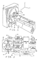
- a computed tomography (CT) imaging system 10 is shown as including a gantry 12 representative of a "third generation" CT scanner.
- Gantry 12 has an x-ray source 14 that projects a beam of x-rays 16 toward a detector array 18 on the opposite side of gantry 12.
- Detector array 18 is divided into channels formed by detector elements 20 which together sense the projected x-rays that pass through a medical patient 22 or other imaging object.
- Each detector element 20 produces an electrical signal that represents the intensity of an impinging x-ray beam and hence the attenuation of the beam as it passes through patient 22.
- gantry 12 and the components mounted thereon rotate about an axis of rotation 24.
- Control mechanism 26 includes an x-ray controller 28 that provides power and timing signals to x-ray source 14 and a gantry motor controller 30 that controls the rotational speed and position of gantry 12.
- a data acquisition system (DAS) 32 in control mechanism 26 samples analog projection data from detector elements 20 and converts the analog data to digital projection data for subsequent processing.
- An image reconstructor 34 receives into its memory 35 the digitized x-ray projection data from DAS 32 and comprises a processor 37 that performs the high speed image reconstruction algorithm as defined by the program signals stored in the memory. The reconstructed image is applied as an input to a computer 36 which stores the image in a mass storage device 38.
- gantry 12 During a scan, gantry 12 often is tilted with respect to the z-axis.
- a driving mechanism tilts gantry 12 about a pivot point (not shown) so that axis of gantry rotation 24 is not parallel to the z-axis.
- An encoder (not shown) is coupled to gantry 12 detects the tilt angle q, i.e., the amount of gantry tilt about the pivot point, and generates pulses indicative of the angular orientation, q, of the gantry about the pivot point.
- the output of the encoder is coupled, for example, to computer 36 or gantry motor controller 30.
- Computer 36 also receives commands and scanning parameters from an operator via console 40 that has a keyboard.
- An associated cathode ray tube display 42 allows the operator to observe the reconstructed image and other data from computer 36.
- the operator supplied commands and parameters are used by computer 36 to provide control signals and information to DAS 32, x-ray controller 28 and gantry motor controller 30.
- computer 36 operates a table motor controller 44 which controls a motorized table 46 to position patient 22 in gantry 12.
- table 46 indexes patient 22 to a location, and allows gantry 12 to rotate about the patient at the location.
- table 46 moves patient 22 through aperture 48 at a table speed, s, equal to a displacement along the z-axis per a rotation of gantry 12.
- four fan beam planes 50 are defined between four rows of detectors 20 and a focal spot 52 of x-ray source 14.
- the gantry plane 54 carrying x-ray source 14 and detector array 18 is angularly displaced from a vertical position at a tilt angle q, causing axis of rotation 24 to be similarly angularly displaced from a longitudinal patient axis 56.
- Each of the four fan beams 50 is displaced a distance d fb along the axis of rotation 24 from gantry plane 54 to its own isometric center of rotation 58.
- isometric center of rotation 58 for each fan beam 50 is displaced from longitudinal patient axis 56 by some isometric offset amount, off fb .
- Offset amount, off fb , for the center of rotation 58 of each fan beam 50 creates problems in image reconstruction using typical reconstruction techniques.
- Typical systems for both axial and helical scanning assume that axis of rotation 24, and hence center of rotation 58 for each fan beam 50 coincides or is parallel to longitudinal patient axis 56.
- Examples of image reconstruction algorithms that may be used for reconstructing an image from helical scan data are disclosed in U.S. Patent No. 5,559,847, U.S. Patent No. 5,541,970, and U.S. Patent No. 5,606,585. Utilizing a tilted gantry 12 with these systems causes the image centers to be shifted relative to longitudinal patient axis 56. This shifting may cause artifacts and other errors in the reconstructed image.
- the present invention comprises image reconstructor 34 that provides tilt-compensated image data 60A-D from raw projection data array 62A-D having different centers of rotation 58.
- Image reconstructor comprises memory 35 (FIG. 2) for storing various data and signals representative of various algorithms, as is discussed below.
- each view of raw digital data array 62A-D from DAS 32 for each fan beam is received at respective preprocessors 64A-D, where the respective beam is preprocessed to correct for various well-known errors such as beam hardening, offsets and variations in detector and channel gain.
- the negative logarithm is taken to provide corrected projection data array 66A-D.
- each corrected projection data array 66A-D is input to a reconstruction operation or algorithm 68A-D that utilizes an axial tilt compensation function or algorithm 70A-D to produce an image data array 72A-D for each fan beam.
- corrected projection data array for each beam 66A-D is input into a corresponding weighting operation or algorithm 74A-D that utilizes a helical tilt compensation function or algorithm 76A-D to provide weighted and tilt compensated projection data.
- the weighted projection data is written into a corresponding location in weighted projection data array 78A-D.
- Each weighted projection data array 78A-D is summed 80 to provide a summed data array 82.
- the magnitude of each pixel in beam 1 array is summed with the magnitude of the corresponding pixels in the beam 2, beam 3 and beam 4 arrays.
- Summed data array 82 is then utilized in a reconstruction operation or algorithm 68E to produce an image data array 72E.
- the resulting image arrays 72A-E may be stored for later use or displayed to the operator.
- the largest relative shift (from the top and bottom detector rows) is 8.66 mm for 4x5 or 5.78 mm for 2x10.
- Y_shift is the function of gantry tilt angle and d fb .
- the term d fb is a function of the collimated thickness of x-ray beam 16, in the direction of axis of rotation 24, and detector row index. Therefore, Y_shift can be determined once these parameters are chosen.
- F_shift [-n, -n+1, ...n-1, n]* ⁇ (Db)/(2 ⁇ ) ⁇ *( s )* tan(q)
- n and Db are the parameters of a z-kernel introduced by the Z-Filtering Reconstruction method as described in U.S. Patent No. 5,606,585.
- F_shift is a function of gantry tilt angle, table speed per rotation, s , the filter's angular displacement and kernel term. Therefore, F_shift can be determined once these parameters are chosen.
- Axial scanning using gantry 12 having a tilt angle q contains only one kind of center-shifting -- Y_shift. This shift, if not compensated, will causes isometric center 58 of image data array 72A-E to be shifted up or down relative to longitudinal patient axis 56 by Y_shift. This slice misalignment causes problems in applications such as 3D, MPR and Paging modes.
- the solution for axial CT is to shift the center of images of both prospective and retrospective reconstruction by an amount equal to Y_shift, but in the opposite direction, to compensate for the intrinsic center-shifting.
- the present invention advantageously provides axial tilt compensation function 70A-D, equal to Y_shift, that is utilized in reconstruction operation 68A-D to provide tilt-compensated image data array 72A-D.
- the tilt compensation for axial CT is exact and causes no adverse impact on IQ and reconstruction speed.
- corrected projection data 66A-D from different detector rows, corresponding to each fan beam plane 50, are combined prior to reconstruction operation 68E.
- This projection data combination is the key concept that provides roughly 4:1 data compression and therefore enables processing multislice data with the current fan beam reconstructing systems within current speed specifications. Unable to apply this combination means a much longer reconstruction time, four time longer, and a different data process architecture for tilted gantry reconstruction.
- the present invention advantageously provides an approximate tilt compensation solution for helical CT scanning.
- tilted gantry applications cause inaccuracies in image reconstruction because fan beam planes 50 do not intersect longitudinal patient axis 56 in the same place as would a non-tilted gantry application. This difference creates problems in the image reconstruction, which rely on the non-tilted gantry beam position.
- D_t 1 t when gantry 12 is tilted.
- table 46 is incremented by 23.08 mm rather than by 20 mm.
- the discrepancy between non-tilted and tilted gantry beam thickness, t causes reconstruction problems.
- p ( s / t )*cos(q)
- s , t , and q are the table speed, beam thickness, and tilt angle, respectively, as defined above.
- 3:1 pitch helical scanning requires a table speed of 4.15 mm/rotation rather than 3.75 mm/rotation.
- the system of the present invention provides a table speed and indexing offset to account for the discrepancy in thickness, t , of x-ray beam 16 at longitudinal patient axis 56 between tilted and non-t
- the system and method of the present invention provide tilt compensation that greatly reduces image blurring.
- the system and method of the present invention allow the use of tilted gantry scans while providing high image quality and without any significant, adverse impact on reconstruction time. Therefore, the present invention provides for the accurate reconstruction of tilted gantry images comprising projection data having different centers of rotation relative to the longitudinal patient axis.
Landscapes
- Health & Medical Sciences (AREA)
- Life Sciences & Earth Sciences (AREA)
- Medical Informatics (AREA)
- Engineering & Computer Science (AREA)
- Radiology & Medical Imaging (AREA)
- Biomedical Technology (AREA)
- Biophysics (AREA)
- Nuclear Medicine, Radiotherapy & Molecular Imaging (AREA)
- Optics & Photonics (AREA)
- Pathology (AREA)
- Physics & Mathematics (AREA)
- High Energy & Nuclear Physics (AREA)
- Heart & Thoracic Surgery (AREA)
- Molecular Biology (AREA)
- Surgery (AREA)
- Animal Behavior & Ethology (AREA)
- General Health & Medical Sciences (AREA)
- Public Health (AREA)
- Veterinary Medicine (AREA)
- Apparatus For Radiation Diagnosis (AREA)
Claims (22)
- Computer-Tomographiesystem (10) enthaltend:wobei die Röntgenquelle (14) um eine Drehachse (24) senkrecht zu dem Schwenkwinkel drehbar ist und Röntgenstrahlen (16) von einem Brennpunkt an jeder von einer Anzahl von Sichten (Views) emittieren kann, die einer Kombination von Drehwinkelwert und einem zugeordneten Schwenkwinkelwert entspricht,ein Gestell (12), das eine Öffnung (48) hat, die ein bildgebendes Objekt umschließen kann, und eine drehbar angebrachte Röntgenquelle (14) und eine gegegenüber liegende Detektoranordnung (18) aufweist, wobei eine Ebene zwischen der Röntgenquelle (14) und der Detektoranordnung (18) eine Gestellebene bildet, die entlang einer Längsachse (56) des Objektes positionierbar ist, wobei das Gestell (12) zu einer Schwenkverschiebung der Gestellebene unter eienem Schwenkwinkel relativ zu der Längsachse in der Lage ist,
wobei die Detektoranordnung (18) eine Anzahl von Detektorelementen (20) aufweist, die eine Anzahl von Fächerbündelebenen zwischen jedem der mehreren Detektorelemente (20) und der Röntgenquelle (14) bilden, wobei jede der mehreren Fächerbündelebenen einen Rotationsmittenwert entlang der Rotationsachse (24) hat und jedes der mehreren Detektorelemente (20) die emittierten Röntgenstrahlen (16) an jeder der mehreren Sichten empfangen kann und Rohprojektoionsdaten liefert, die die Intensität der Röntgenstrahlen (16) anzeigen, die an jeder der mehreren Sichten empfangen werden, und
ein Computersystem (34 und 36) in Verbindung mit der Detektoranordnung (18), wobei das Computersystem (34 und 36) einen Speicher hat zum Speichern von Daten, die Daten einschließen, die die Rohprojektionsdaten darstellen, und der Drehwinkelwert, der Schwenkwinkelwert und der Rotationsmittenwert den Rohprojektionsdaten entsprechen, wobei das Computersystem (34 und 36) ferner Programmsignale aufweist, die einen Algorithmus zum Konstruieren von Bilddaten aus den Rohprojektionddaten darstellen, wobei der Algorithmus die den Bilddaten zugeordneten Rotationsmittenwerte um eine Versetzungsgrösse verschiebt, die eine Funktion des Schwenkwinkels ist, so daß die Bilddaten um die Längsachse (56) des Objektes zentriert sind. - System (10) nach Anspruch 1, wobei die Versetzungsgrösse beträgt:dFB = die Strecke entlang der Drehachse zwischen der Gestellebene und der Fächerbündelebene (50), die den Rohprojektionsdaten entspricht, die den Bilddaten zugeordnet sind, undq = der Schwenkwinkelwert, der den den Bilddaten zugeordneten Rohprojektionsdaten entspricht.
- System (10) nach Anspruch 1, wobei das Computersystem (34 und 36) ferner Programmsignale aufweist, die einen Algorithmus zur Fehlerkorrektur der Rohprojektionsdaten darstellen, und entsprechende korrigierte Projektionsdaten liefert, wobei der Algorithmus ferner die korrigierten Projektionsdaten rekonstruiert, die die Bilddaten liefern.
- System (10) nach Anspruch 3, wobei der Algorithmus die Rotationsmittenwerte, die den Bilddatren zugeordnet sind, die mit jeder der mehreren Fächerbündelebenen (50) verbunden sind, um die Versetzungsgrösse verschiebt, um die relative Position von allen der mehreren Bilddaten auszurichten.
- System (10) nach Anspruch 3, wobei der Algorithmus die Rotationsmittenwerte der Projektionsdaten um die Versetzungsgrösse verschiebt.
- System (10) nach Anspruch 1, wobei das Computersystem (34 und 36) ferner Signale aufweist, die einen Algorithmus darstellen, der das bildgebende Objekt durch die Öffnung (48) in Indexierschritten vorschiebt, die ein Vielfaches von einer Dikke einer Scheibe der Bilddaten sind, wobei der Indexierschritt, der als D_t bezeichnet ist, definiert ist durch:
- System (10) nach Anspruch 1, wobei die Detektoranordnung (18) ferner eine Anzahl von Kanälen enthält, jeder an einer Winkelverschiebung um die Öffnung (18) relativ zu der Röntgenquelle (14), und wobei das Computersystem (34 und 36) ferner Programmsignale aufweist, die einen Algorithmus zur Fehlerkorrektur der Rohprojektionsdaten darstellen, und entsprechende korrigierte Projektionsdaten liefert, wobei der Algorithmus die korrigierten Projektionsdaten mit einer Gewichtungsfunktion wichtet, um gewichtete Projektionsdaten zu liefern, wobei der Algorithmus ferner eine Anzahl von gewichteten Projektionsdaten, die einer Anzahl von Sichten entsprechen, und eine Anzahl von Fächerbündelebenen (50) kombiniert, um gewichtete Summendaten zu bilden, wobei der Algorithmus ferner die gewichteten Summendaten rekonstruiert, um die Bilddaten zu liefern.
- System (10) nach Anspruch 7, wobei der Algorithmus den Rotationsmittenwert von allen korrigierten Projektionsdaten um die Versetzungsrösse verschiebt.
- System (10) nach Anspruch 8, wobei die Versetzungsgrösse beträgt:dFB = Strecke entlang der Drehachse zwischen der Gestellebene und der Fächerbündelebene (50), die den Rohprojektionsdaten entspricht, die den Bilddaten zugeordnet sind, undq = der Schwenkwinkelwert, der den den Bilddaten zugeordneten Rohprojektionsdaten entspricht.
- System (10) nach Anspruch 8, wobei ferner ein Tisch (46) vorgesehen ist, der das bildgebende Objekt durch die Öffnung mit einer Tischvorschubgeschwindigkeit s pro Rotation der Röntgenquelle um die Öffnung (48) bewegen kann, und wobei die Versetzugsgrösse die korrigierten Projektionsdaten entlang der Kanalrichtung für jede Sicht und jeden Kanal verschiebt und die Versetzungsgrösse beträgt:b = der Rotationswinkelwert,Lfb = Strecke von dem Brennpunkt der Röntgenquelle zur Drehachse,det_dgamma = das Winkelinkrement des Detektorkanals,dFB = Strecke entlang der Drehachse zwischen der Gestellebene und der Fächerbündelebene, die den Rohprojektionsdaten entspricht, die den Bilddaten zugeordnet sind, undq = der Schwenkwinkelwert, der den den Bilddaten zugeordneten Rohprojektionsdaten entspricht, und
- System nach Anspruch 10, wobei das Computersystem ferner Signale aufweist, die einen Algorithmus darstellen, der das bildgebende Objekt durch die Öffnung mit der Tischgeschwindigkeit s vorschiebt, die definiert ist durch:p = Wendelsteigung,q = der Schwenkwinkelwert, der den Rohprojektionsdaten entspricht, die den Bilddaten zugeordnet sind, undt die Dicke einer Scheibe der Bilddaten an der Längsachse des Patienten ist.
- Verfahren zum Kompensieren eines Gestellschwenkwinkels, wenn Computer-Tomographiebilder von einem Vielfach-Fächerbündel-Detektionssystem erhalten werden, wobei das Verfahren die Schritte enthält:(a) Gewinnen von Bilddaten enthaltend eine Anzahl von Projektionsdaten, die die Röntgenstrahlenschwächung eines bildgebenden Objektes darstellen, die von einer Röntgenquelle emittiert und von einer Detektoranordnung empfangen werden, wobei die Röntgenquelle um eine Öffnung, die das bildgebende Objekt umschließt, und um eine Drehachse rotiert, die senkrecht zu einer Ebene des Gestells ist,(b) Gewinnen von Daten, die Rotationsmittenwerten entsprechen, die den Projektionsdaten zugeordnet sind, und(c) Einstellen der Positionierung der Bilddaten um eine Versetzungsgrösse, die eine Funktion der Rotationsmittenwerte und des Schwenkwinkelwertes ist.
- Verfahren nach Anspruch 12, ferner die Schritte enthaltend:wobei q = der Schwenkwinkelwert, der den den Bilddaten zugeordneten Rohprojektionsdaten entspricht.(a) Gewinnen eines Wertes dFB für die Strecke entlang der Drehachse zwischen der Gestellebene und der Fächerbündelebene, die den Rohprojektionsdaten entspricht, die den Bilddaten zugeordnet sind, und(b) Ermitteln der Versetzungsgrösse:
- Verfahren nach Anspruch 12, wobei ferner die Schritte vorgesehen sind, daß korrigierte Projektionsdaten gewonnen werden, die auf einem angewendeten Fehlerkorrekturwert für jedes der Projektionsdaten basieren, und die korrigierten Projektionsdaten rekonstruiert werden, um die Bilddaten zu liefern.
- Verfahren nach Anspruch 14, wobei der Einstellschritt den Rotationsmittenwert der Bilddaten, die jedem Detektorfächerbündel zugeordnet sind, um eine Versetzungsgrösse verschiebt, um die relative Position von allen Bilddaten auszurichten.
- Verfahren nach Anspruch 14, wobei der Einstellschritt den Rotationsmittenwert von jedem der mehreren Projektionsdaten um die Versetzungsgrösse verschiebt.
- Verfahren nach Anspruch 12, wobei ferner der Schritt vorgesehen ist, daß das bildgebende Objekt durch die Öffnung in Indexierschritten vorgeschoben wird, die ein Vielfaches der Dicke von einer Scheibe der Bilddaten ist, wobei der Indexierschrittwert, der mit D_t bezeichnet ist, definiert ist durch:
- Verfahren nach Anspruch 12, ferner die Schritte enthaltend:(a) Gewinnen von korrigierten Projektionsdaten, die auf einem angewendeten Fehlerkorrekturwert für jedes der mehreren Projektionsdaten basieren, wobei alle korrigierten Projektionsdaten einen entsprechenden Sichtwert, der den Drehwinkel der Röntgenquelle darstellt, und einen entsprechenden Kanalwert haben, der eine Winkelverschiebung von einem Kanal der Detektoranordnung relativ zur Röntgenquelle darstellt,(b) Gewichten der korrigierten Projektionsdaten mit einer Gewichtungsfunktion, um gewichtete Projektionsdaten zu liefern,(c) Kombinieren einer Anzahl der gewichteten Projektionsdaten, die eine Anzahl von Sichtwerten haben und einer Anzahl von Detektor-Fächerbündelebenen zugeordnet sind, um gewichtete Summendaten zu bilden, und(d) Rekonstruieren der gewichteten Summendaten, um die Bilddaten zu liefern.
- Verfahren nach Anspruch 18, der Einstellschritt den Rotationsmittenwert, der jedem der korrigierten Projektionsdaten zugeordnet ist, um die Versetzungsgrösse verschiebt.
- Verfahren nach Anspruch 19, ferner die Schritte enthaltend:(a) Gewinnen eines Wertes dFB für die Strecke entlang der Drehachse zwischen der Gestellebene und der Fächerbündelebene, die den Rohprojektionsdaten entspricht, die den Bilddaten zugeordnet sind,(b) Gewinnen eines Schwenkwinkelwertes q, der den Projektionsdaten entspricht, die den Bilddaten zugeordnet sind, und(c) Ermitteln der Versetzungsgrösse:
- Verfahren nach Anspruch 18, ferner die Schritte enthaltend:wobei:(a) Vorschieben des bildgebenden Objektes durch die Öffnung mit einer Geschwindigkeit s pro Rotation der Röntgenquelle um die Öffnung, und wobei die Detektoranordnung eine Anzahl von Kanälen aufweist, und(b) Ermitteln der Versetzungsgrösse, die die korrigierten Projektionsdaten entlang der Kanalrichtung für jede Sicht und jeden Kanal verschiebt, wobei der Versetzungsgrössenwert beträgt:b = der Rotationswinkelwert,Lfb = Strecke von dem Brennpunkt der Röntgenquelle zur Drehachse,det_dgamma = das Winkelinkrement des Detektorkanals,dFB = Strecke entlang der Drehachse zwischen der Gestellebene und der Fächerbündelebene, die den Rohprojektionsdaten entspricht, die den Bilddaten zugeordnet sind, undq = der Schwenkwinkelwert, der den den Bilddaten zugeordneten Rohprojektionsdaten entspricht, und
- Verfahren nach Anspruch 18, ferner die Schritte enthaltend:(a) Ermitteln einer Wendelsteigung p,(b) Ermitteln einer Dicke t von einer Scheibe der Bilddaten an einer Längsachse des bildgebenden Objektes und(c) Vorschieben des bildgebenden Objektes durch die Öffnung mit einer Geschwindigkeit s, die definiert ist durch:q = der Gestellschwenkwinkelwert, der den Rohprojektionsdaten entspricht, die den Bilddaten zugeordnet sind.
Applications Claiming Priority (2)
| Application Number | Priority Date | Filing Date | Title |
|---|---|---|---|
| US140131 | 1980-04-14 | ||
| US09/140,131 US6229869B1 (en) | 1998-08-25 | 1998-08-25 | Tilted gantry image correction for a multislice computed tomography system |
Publications (2)
| Publication Number | Publication Date |
|---|---|
| EP0981996A1 EP0981996A1 (de) | 2000-03-01 |
| EP0981996B1 true EP0981996B1 (de) | 2002-07-31 |
Family
ID=22489896
Family Applications (1)
| Application Number | Title | Priority Date | Filing Date |
|---|---|---|---|
| EP99306600A Expired - Lifetime EP0981996B1 (de) | 1998-08-25 | 1999-08-20 | Bildkorrektur für ein geneigtes Gehäuse in einem Mehrschicht-Computertomograph |
Country Status (5)
| Country | Link |
|---|---|
| US (1) | US6229869B1 (de) |
| EP (1) | EP0981996B1 (de) |
| JP (1) | JP4465062B2 (de) |
| DE (1) | DE69902326T2 (de) |
| IL (1) | IL131401A (de) |
Families Citing this family (31)
| Publication number | Priority date | Publication date | Assignee | Title |
|---|---|---|---|---|
| US6332013B1 (en) * | 1999-12-28 | 2001-12-18 | General Electric Company | Methods and apparatus for tilted helical reconstruction multislice CT |
| US6463117B1 (en) * | 2000-11-22 | 2002-10-08 | Ge Medical Systems Global Technology Company, Llc | Methods and apparatus for tilted helical image reconstruction in CT imaging |
| JP2003000585A (ja) * | 2001-06-11 | 2003-01-07 | Ge Medical Systems Global Technology Co Llc | X線ctシステム及びその制御方法並びに記憶媒体 |
| US6704392B2 (en) * | 2001-07-03 | 2004-03-09 | Ge Medical Systems Global Technology Company, Llc | X-ray tube and method having tilted rotation axis |
| JP4175791B2 (ja) * | 2001-08-20 | 2008-11-05 | ジーイー・メディカル・システムズ・グローバル・テクノロジー・カンパニー・エルエルシー | 画像生成方法およびx線ct装置 |
| US7020236B2 (en) * | 2002-05-06 | 2006-03-28 | Koninklijke Philips Electronics N.V. | Cone beam CT scanners with reduced scan length |
| US6751283B2 (en) | 2002-08-06 | 2004-06-15 | Koninklijke Philips Electronics, N.V. | Reconstruction method for tilted-gantry computed tomography |
| US6917666B2 (en) * | 2002-12-19 | 2005-07-12 | General Electric Company | System and method for table/gantry alignment in imaging systems |
| JP4469555B2 (ja) * | 2003-03-28 | 2010-05-26 | 株式会社東芝 | X線コンピュータ断層撮影装置 |
| CN100387195C (zh) * | 2003-11-07 | 2008-05-14 | Ge医疗系统环球技术有限公司 | 偏移量测量方法、身体活动检测方法及x射线ct装置 |
| US7167538B2 (en) * | 2004-03-30 | 2007-01-23 | Siemens Medical Solutions Usa, Inc. | Exact volume imaging involving multiple partial scans |
| JP4032357B2 (ja) | 2004-05-21 | 2008-01-16 | ソニー株式会社 | 画像情報処理装置および方法、並びにプログラム |
| JP2006000225A (ja) * | 2004-06-15 | 2006-01-05 | Canon Inc | X線ct装置 |
| JP2006055309A (ja) * | 2004-08-19 | 2006-03-02 | Ge Medical Systems Global Technology Co Llc | X線ct撮影方法およびx線ct装置 |
| US7394887B2 (en) * | 2004-10-15 | 2008-07-01 | General Electric Company | Method and apparatus for reconstruction of tilted cone beam data |
| US7492856B2 (en) * | 2005-12-07 | 2009-02-17 | Ge Security, Inc. | Apparatus and method for providing an orthographic projection from helical scan data |
| US7548604B2 (en) * | 2007-01-04 | 2009-06-16 | General Electric Company | Method and apparatus for reduction of metal artifacts in CT imaging |
| US7983460B2 (en) * | 2007-06-08 | 2011-07-19 | General Electric Company | Method and system for performing high temporal resolution bolus detection using CT image projection data |
| JP2009045092A (ja) * | 2007-08-13 | 2009-03-05 | Canon Inc | Ct撮影装置及びその制御方法 |
| DK2282050T3 (en) * | 2009-06-30 | 2016-06-06 | Siemens Ag | Method for inspecting a wind turbine blade |
| CN101987020B (zh) * | 2009-08-04 | 2014-09-17 | Ge医疗系统环球技术有限公司 | 倾斜图像扫描方法和重建方法及装置 |
| US9084542B2 (en) | 2009-11-10 | 2015-07-21 | General Electric Company | Apparatus and methods for computed tomography imaging |
| US9042514B2 (en) | 2012-05-18 | 2015-05-26 | Analogic Corporation | Dose reduction via dynamic collimation adjustment for targeted field of view and/or digital tilt CT |
| US9089266B2 (en) * | 2013-04-19 | 2015-07-28 | Kabushiki Kaisha Toshiba | Tilted detector array for medical imaging systems including computed tomography |
| CN103218834B (zh) * | 2013-04-25 | 2016-05-04 | 重庆大学 | 一种基于点扩展函数的工业ct图像重建中心定位方法 |
| US10004564B1 (en) * | 2016-01-06 | 2018-06-26 | Paul Beck | Accurate radiographic calibration using multiple images |
| US10010372B1 (en) | 2016-01-06 | 2018-07-03 | Paul Beck | Marker Positioning Apparatus |
| CN109171790B (zh) * | 2018-09-26 | 2022-03-15 | 东软医疗系统股份有限公司 | 一种ct扫描数据的处理方法、装置及ct机 |
| CN109171793B (zh) * | 2018-11-01 | 2022-10-14 | 上海联影医疗科技股份有限公司 | 一种角度检测和校正方法、装置、设备和介质 |
| WO2020252094A1 (en) * | 2019-06-11 | 2020-12-17 | Board Of Regents, The University Of Texas System | Computed tomography (ct) imaging artifact reduction technique making use of tilted scans |
| US12469594B1 (en) * | 2022-02-15 | 2025-11-11 | Trimedx, Llc | Predictive work order devices, systems, and methods |
Family Cites Families (7)
| Publication number | Priority date | Publication date | Assignee | Title |
|---|---|---|---|---|
| US4088888A (en) * | 1977-02-25 | 1978-05-09 | General Electric Company | Gantry for computed tomography |
| US4385397A (en) * | 1981-10-23 | 1983-05-24 | General Electric Company | Parallax corrected external alignment lights |
| US4989142A (en) * | 1988-10-24 | 1991-01-29 | General Electric Company | Three-dimensional images obtained from tomographic slices with gantry tilt |
| JPH084586B2 (ja) * | 1989-02-07 | 1996-01-24 | 浜松ホトニクス株式会社 | Ct装置 |
| US5848126A (en) * | 1993-11-26 | 1998-12-08 | Kabushiki Kaisha Toshiba | Radiation computed tomography apparatus |
| US5606585A (en) * | 1995-12-21 | 1997-02-25 | General Electric Company | Methods and apparatus for multislice helical image reconstruction in a computer tomography system |
| US5799054A (en) * | 1996-12-31 | 1998-08-25 | General Electric Company | Methods and apparatus for stabilizing a gantry in a computed tomography system |
-
1998
- 1998-08-25 US US09/140,131 patent/US6229869B1/en not_active Expired - Lifetime
-
1999
- 1999-08-15 IL IL13140199A patent/IL131401A/en not_active IP Right Cessation
- 1999-08-20 EP EP99306600A patent/EP0981996B1/de not_active Expired - Lifetime
- 1999-08-20 DE DE69902326T patent/DE69902326T2/de not_active Expired - Lifetime
- 1999-08-24 JP JP23635299A patent/JP4465062B2/ja not_active Expired - Lifetime
Also Published As
| Publication number | Publication date |
|---|---|
| DE69902326T2 (de) | 2003-03-20 |
| US6229869B1 (en) | 2001-05-08 |
| IL131401A (en) | 2002-11-10 |
| JP2000083947A (ja) | 2000-03-28 |
| EP0981996A1 (de) | 2000-03-01 |
| IL131401A0 (en) | 2001-01-28 |
| JP4465062B2 (ja) | 2010-05-19 |
| DE69902326D1 (de) | 2002-09-05 |
Similar Documents
| Publication | Publication Date | Title |
|---|---|---|
| US6229869B1 (en) | Tilted gantry image correction for a multislice computed tomography system | |
| US6370218B1 (en) | Methods and systems for determining x-ray beam position in multi-slice computed tomography scanners | |
| US6421411B1 (en) | Methods and apparatus for helical image artifact reduction | |
| US5663995A (en) | Systems and methods for reconstructing an image in a CT system performing a cone beam helical scan | |
| US6256364B1 (en) | Methods and apparatus for correcting for x-ray beam movement | |
| US5430785A (en) | Detector channel gain calibration using focal spot wobble | |
| US5559847A (en) | Systems, methods and apparatus for reconstructing images in a CT system implementing a helical scan | |
| US6324247B1 (en) | Partial scan weighting for multislice CT imaging with arbitrary pitch | |
| EP0426464A2 (de) | Rechnergesteurtes tomographisches Bildrekonstruktionsverfahren für Spiralabtasten | |
| US6134292A (en) | Methods and apparatus for reducing z-axis non-uniformity artifacts | |
| US5513236A (en) | Image reconstruction for a CT system implementing a dual fan beam helical scan | |
| US5606585A (en) | Methods and apparatus for multislice helical image reconstruction in a computer tomography system | |
| US5469486A (en) | Projection domain reconstruction method for helical scanning computed tomography apparatus with multi-column detector array employing overlapping beams | |
| US5400379A (en) | Multi-slice x-ray CT using a detector mask | |
| US6381297B1 (en) | High pitch reconstruction of multislice CT scans | |
| US5469487A (en) | CT system with twin fan beam helical scan | |
| EP0430506B1 (de) | Verkleinerung von Patientenversetzungsartefakt in tomographischer Bildverarbeitung | |
| US20050265523A1 (en) | C-arm device with adjustable detector offset for cone beam imaging involving partial circle scan trajectories | |
| US5761257A (en) | Normalizing projection data in a computed tomography system | |
| US5974110A (en) | Helical reconstruction algorithm | |
| US6343110B1 (en) | Methods and apparatus for submillimeter CT slices with increased coverage | |
| US5541970A (en) | Image reconstruction for a CT system implementing a four fan beam helical scan | |
| US7394887B2 (en) | Method and apparatus for reconstruction of tilted cone beam data | |
| US5732118A (en) | Methods and apparatus for image reconstruction in a multislice computed tomography system | |
| US6307908B1 (en) | System and method for data interpolation in a multislice x-ray computed tomography system |
Legal Events
| Date | Code | Title | Description |
|---|---|---|---|
| PUAI | Public reference made under article 153(3) epc to a published international application that has entered the european phase |
Free format text: ORIGINAL CODE: 0009012 |
|
| AK | Designated contracting states |
Kind code of ref document: A1 Designated state(s): DE NL |
|
| AX | Request for extension of the european patent |
Free format text: AL;LT;LV;MK;RO;SI |
|
| 17P | Request for examination filed |
Effective date: 20000901 |
|
| AKX | Designation fees paid |
Free format text: DE NL |
|
| GRAG | Despatch of communication of intention to grant |
Free format text: ORIGINAL CODE: EPIDOS AGRA |
|
| 17Q | First examination report despatched |
Effective date: 20011120 |
|
| GRAG | Despatch of communication of intention to grant |
Free format text: ORIGINAL CODE: EPIDOS AGRA |
|
| GRAH | Despatch of communication of intention to grant a patent |
Free format text: ORIGINAL CODE: EPIDOS IGRA |
|
| GRAH | Despatch of communication of intention to grant a patent |
Free format text: ORIGINAL CODE: EPIDOS IGRA |
|
| GRAA | (expected) grant |
Free format text: ORIGINAL CODE: 0009210 |
|
| AK | Designated contracting states |
Kind code of ref document: B1 Designated state(s): DE NL |
|
| REF | Corresponds to: |
Ref document number: 69902326 Country of ref document: DE Date of ref document: 20020905 |
|
| PLBE | No opposition filed within time limit |
Free format text: ORIGINAL CODE: 0009261 |
|
| STAA | Information on the status of an ep patent application or granted ep patent |
Free format text: STATUS: NO OPPOSITION FILED WITHIN TIME LIMIT |
|
| 26N | No opposition filed |
Effective date: 20030506 |
|
| PGFP | Annual fee paid to national office [announced via postgrant information from national office to epo] |
Ref country code: NL Payment date: 20130826 Year of fee payment: 15 |
|
| REG | Reference to a national code |
Ref country code: NL Ref legal event code: V1 Effective date: 20150301 |
|
| PG25 | Lapsed in a contracting state [announced via postgrant information from national office to epo] |
Ref country code: NL Free format text: LAPSE BECAUSE OF NON-PAYMENT OF DUE FEES Effective date: 20150301 |
|
| PGFP | Annual fee paid to national office [announced via postgrant information from national office to epo] |
Ref country code: DE Payment date: 20160826 Year of fee payment: 18 |
|
| REG | Reference to a national code |
Ref country code: DE Ref legal event code: R119 Ref document number: 69902326 Country of ref document: DE |
|
| PG25 | Lapsed in a contracting state [announced via postgrant information from national office to epo] |
Ref country code: DE Free format text: LAPSE BECAUSE OF NON-PAYMENT OF DUE FEES Effective date: 20180301 |