EP0982103B1 - Dispositif de verrouillage automatique pour une broche - Google Patents
Dispositif de verrouillage automatique pour une broche Download PDFInfo
- Publication number
- EP0982103B1 EP0982103B1 EP98116378A EP98116378A EP0982103B1 EP 0982103 B1 EP0982103 B1 EP 0982103B1 EP 98116378 A EP98116378 A EP 98116378A EP 98116378 A EP98116378 A EP 98116378A EP 0982103 B1 EP0982103 B1 EP 0982103B1
- Authority
- EP
- European Patent Office
- Prior art keywords
- locking
- spindle
- cams
- automatic spindle
- openings
- Prior art date
- Legal status (The legal status is an assumption and is not a legal conclusion. Google has not performed a legal analysis and makes no representation as to the accuracy of the status listed.)
- Expired - Lifetime
Links
- 238000006073 displacement reaction Methods 0.000 claims description 8
- 238000005553 drilling Methods 0.000 claims description 4
- 230000033001 locomotion Effects 0.000 claims description 4
- 230000008878 coupling Effects 0.000 claims 2
- 238000010168 coupling process Methods 0.000 claims 2
- 238000005859 coupling reaction Methods 0.000 claims 2
- 230000000295 complement effect Effects 0.000 claims 1
- 238000004519 manufacturing process Methods 0.000 description 4
- 210000000078 claw Anatomy 0.000 description 2
- 230000005540 biological transmission Effects 0.000 description 1
- 230000015572 biosynthetic process Effects 0.000 description 1
- 238000010276 construction Methods 0.000 description 1
- 230000007547 defect Effects 0.000 description 1
- 230000000694 effects Effects 0.000 description 1
- 238000007373 indentation Methods 0.000 description 1
- 230000007257 malfunction Effects 0.000 description 1
- 230000007935 neutral effect Effects 0.000 description 1
Images


Classifications
-
- B—PERFORMING OPERATIONS; TRANSPORTING
- B25—HAND TOOLS; PORTABLE POWER-DRIVEN TOOLS; MANIPULATORS
- B25F—COMBINATION OR MULTI-PURPOSE TOOLS NOT OTHERWISE PROVIDED FOR; DETAILS OR COMPONENTS OF PORTABLE POWER-DRIVEN TOOLS NOT PARTICULARLY RELATED TO THE OPERATIONS PERFORMED AND NOT OTHERWISE PROVIDED FOR
- B25F5/00—Details or components of portable power-driven tools not particularly related to the operations performed and not otherwise provided for
- B25F5/001—Gearings, speed selectors, clutches or the like specially adapted for rotary tools
-
- Y—GENERAL TAGGING OF NEW TECHNOLOGICAL DEVELOPMENTS; GENERAL TAGGING OF CROSS-SECTIONAL TECHNOLOGIES SPANNING OVER SEVERAL SECTIONS OF THE IPC; TECHNICAL SUBJECTS COVERED BY FORMER USPC CROSS-REFERENCE ART COLLECTIONS [XRACs] AND DIGESTS
- Y10—TECHNICAL SUBJECTS COVERED BY FORMER USPC
- Y10T—TECHNICAL SUBJECTS COVERED BY FORMER US CLASSIFICATION
- Y10T408/00—Cutting by use of rotating axially moving tool
- Y10T408/94—Tool-support
- Y10T408/95—Tool-support with tool-retaining means
-
- Y—GENERAL TAGGING OF NEW TECHNOLOGICAL DEVELOPMENTS; GENERAL TAGGING OF CROSS-SECTIONAL TECHNOLOGIES SPANNING OVER SEVERAL SECTIONS OF THE IPC; TECHNICAL SUBJECTS COVERED BY FORMER USPC CROSS-REFERENCE ART COLLECTIONS [XRACs] AND DIGESTS
- Y10—TECHNICAL SUBJECTS COVERED BY FORMER USPC
- Y10T—TECHNICAL SUBJECTS COVERED BY FORMER US CLASSIFICATION
- Y10T409/00—Gear cutting, milling, or planing
- Y10T409/30—Milling
- Y10T409/309352—Cutter spindle or spindle support
-
- Y—GENERAL TAGGING OF NEW TECHNOLOGICAL DEVELOPMENTS; GENERAL TAGGING OF CROSS-SECTIONAL TECHNOLOGIES SPANNING OVER SEVERAL SECTIONS OF THE IPC; TECHNICAL SUBJECTS COVERED BY FORMER USPC CROSS-REFERENCE ART COLLECTIONS [XRACs] AND DIGESTS
- Y10—TECHNICAL SUBJECTS COVERED BY FORMER USPC
- Y10T—TECHNICAL SUBJECTS COVERED BY FORMER US CLASSIFICATION
- Y10T409/00—Gear cutting, milling, or planing
- Y10T409/30—Milling
- Y10T409/309352—Cutter spindle or spindle support
- Y10T409/309408—Cutter spindle or spindle support with cutter holder
Definitions
- DE 297 15 257 U1 shows a driving device for a spindle of a motor-driven, hand-held work tool, in particular a screwdriver or impact wrench, with an output part which is connected to the spindle in a manner fixed against relative rotation, which in both directions of rotation of the spindle via clamping bodies in the form of rollers Freewheel can be coupled with a ring fixed to the housing, with a drive part which is arranged coaxially with the spindle and has unlocking elements which cooperate with the rollers acting as clamping bodies, which release the clamping bodies when the drive part is driven, so that the driven part is uncoupled and rotatable from the ring fixed to the housing, and with torque-transmitting driving surfaces provided on the driven part and the drive part for motor-driven drive of the spindle, the driving surfaces being at a greater distance from one another than that between the unlocking element in the neutral position of the
- the drive part has claws which are spatially separated from the unlocking element and which project into the driven part, the surfaces of the claws and driving openings facing each other in the respective direction of rotation forming the torque-transmitting driving surfaces.
- a total of six clamping bodies in the form of balls are provided in the driving device.
- the construction of such an automatic spindle lock or driving device is very complex. This results in a complex and costly assembly, since in addition to the drive part and the driven part, six clamping bodies have to be installed. With such a large number of moving parts, malfunctions, failures and defects in the spindle lock cannot be ruled out.
- a spindle lock with an also complex Structure also goes from, for example EP 0 761 350 A1.
- the object of the invention is an automatic Spindle lock for hand tools of the generic type Kind in such a way that they as little as possible Items included, is easy to manufacture and works as insensitively as possible and with little wear.
- unlocking elements one or more the drive part arranged control cams and one or several of these by rotating the Drive part sliding control cam comprises such that the locking part and the locking part by axial displacement of the locking part and / or the locking part are decoupled, with a simple structure and this results in a reliable manufacture and low-wear functioning of the automatic Spindle lock enables.
- the drive part and the locking part concerns are pure in principle, the most varied of embodiments conceivable.
- locking part is fixed to the housing, with openings is provided and arranged concentrically to the spindle, locking cams arranged on the locking part can be engaged by axial displacement of the locking part are.
- a locking part provided with openings is easy to manufacture and easy to enclose assemble.
- the locking part is integrally formed with the housing. In this Fall can be an additional assembly of the locking part completely eliminated.
- the openings each offset by the same angle in the locking part are arranged. This enables quick Spindle lock in both directions of rotation of the spindle.
- Locking cams and the control cams each in succession are arranged on the locking part, whereby they are offset by the same angles as the Openings in the locking part.
- the locking part is preferably opposite one in Resetting force acting in the direction of the locking part Return spring arranged axially displaceable on the spindle. This return spring ensures that the arranged on the locking part Locking cam in the idle state of the hand tool in the Intervene in the openings of the locking part.
- the especially with a hand tool with a Planetary gear and with a torque clutch very much can be used advantageously, it is provided that the locking between the housing and the locking part via a locking part assigned to the housing he follows.
- the locking part is, for example, a planet carrier of a planetary gear.
- the drive element is preferably a ring gear of the Planetary gear.
- the openings around each have the same angle arranged in the planet carrier are. This will quickly lock in both Direction of rotation of the spindle allows.
- the locking cams and the control cams are successive arranged on the locking part, being around the same angles are offset as the openings in the Planet carrier.
- the axially displaceable locking part is advantageous against one towards the planet gear acting restoring force of a return spring on the housing non-rotatably arranged. Through this return spring ensured that the on the locking part Arranged locking cams in the idle state of the hand tool into the openings of the acting as a locking part Intervene planetary gear.
- the ring gear is part of a torque clutch, the Periodicity of sprags of the torque clutch Periodicity of the control tracks or control cams corresponds.
- control tracks arranged on the drive part can be limited by a one-sided stop. To this A precise disengagement of the locking part is indicated the stripping section and vice versa and realized undesired indentation of these two parts avoided.
- control lanes themselves can be used in a wide variety of ways Way be trained.
- One in particular embodiment advantageous in terms of production provides that the control tracks have a footprint, one in substantially flat slope surface with an axial direction arranged slope and a to the Sloping surface adjacent plane, perpendicular to Have plateau surface running in the axial direction.
- a hand tool for example a drill, whose Front part is shown in Fig. 1, comprises a housing 10, in which a spindle 20 is rotatably mounted.
- the Spindle 20 is driven by a drive shaft 30 (not shown) motor via a drive part trained ring gear 34 which is rotatably connected to the spindle 20 connected, driven.
- This is the drive shaft 30 of the engine at its front end with teeth 32 provided in an internal toothing of the ring gear 34th intervenes.
- An automatic spindle lock includes the Ring gear 34 has a locking part 40 fixed to the housing Shape of a locking disc and a locking part 50, against the restoring force of a return spring 60 on in the area of the locking part 50 polygonal chamfered sliding surfaces 22 of the spindle 20 is axially displaceable.
- the spindle 20 is used for recording a tool (not shown), for example of a drill using a rotatable clamping element 26 can be fastened in a spindle opening.
- Control cams 54 on the locking member 50th are arranged on control tracks 38 which are connected to the ring gear 34 on the side facing the locking part 50 are provided along such that the locking member 50 an axial movement against the restoring force of the Spring 60, i.e. executes away from the ring gear 34.
- the Control tracks 38 and control cams 54 act so together that an axial movement so far takes place that the locking cam 52 out of the openings 42 are disengaged in the locking disk 40. On such disengagement occurs in both Direction of rotation of the spindle 20. In this disengaged
- the spindle 20 is driven by the ring gear 34 Drive shaft 30 driven and can rotate freely. This state is in Fig. 1 in the lower half shown.
- control tracks 38 arranged on the ring gear 34 a base 38a, a substantially flat one Slope surface 38b with one arranged in the axial direction Slope and one on the slope surface 38b subsequent flat, perpendicular to the axial direction Plateau surface 38c.
- a stop cam 37 for the Control cams 54 may be provided (Fig. 2). In this Position is the axial displacement of the locking part 50 maximum.
- the locking cams 52 are completely from the Openings 42 of the locking part 40 disengaged.
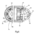
- the locking member is 120 rotationally fixed to the housing 10 provided with projections 130 assigned and points to the drive part 110 facing side locking cams 122 and control cams 124, as can be seen in particular from FIG. 6.
- a locking part acting planet carrier 140 Concentric to the ring gear 110 is a locking part acting planet carrier 140 arranged, which openings offset from each other by the same angle 142 has.
- the openings 142 and the locking cams 122 are each on the planet carrier 140 and the Locking part 120 at equal angles to one another offset so that the locking cams 122 snap into place Locking part 120 in the openings 142 of the Planet carrier 140 is possible.
- the ring gear 110 also has on its end face Guideways for sprags 114 on the opposite of Restoring force of a return spring 115 on each other or are pressed onto the guideway 113.
- the guideways 113 so periodically on the Ring gear 110 are arranged that depending on the adjustable spring force of the return spring 115 a Torque transmission is possible.
- control tracks 116 comprise a plane Base area 116a, a flat slope surface 110b in Circumferential direction and a further plane opposite the Base 116a in the direction of the locking part 120 axially staggered plateau surface 116c.
- the control cam 124 slide on projections 130 guided axially Locking part 120 against the restoring force of Return spring 150 on the slope surface 116b on the Plateau surface 116c and in this way effect one Axial displacement of the locking part 120.
- the slope the slope surfaces 116b is designed so that a Axial displacement of the locking part 120 results, which is so large that the locking cams 122 from the Openings 142 of the planet gear 140 are disengaged.
- the spindle 20 is driven by the motor.
- a tool with the motor stopped becomes a by rotating a clamping element 190
- Rotational driving of the locking member 120 causes that the control cam 124 in the reverse direction from of the plateau surface 116c over the slope surface 116b the base 116a slide in which the locking cams 122 engage in the openings 142 of the planet gear 140.
- the spindle 20 is locked, it can Tools, for example drills or screwing tools by rotating the tensioning element 190 in the intended Recordings are attached.
Landscapes
- Engineering & Computer Science (AREA)
- Mechanical Engineering (AREA)
- Finish Polishing, Edge Sharpening, And Grinding By Specific Grinding Devices (AREA)
- Portable Power Tools In General (AREA)
- One-Way And Automatic Clutches, And Combinations Of Different Clutches (AREA)
- Details Of Spanners, Wrenches, And Screw Drivers And Accessories (AREA)
Claims (15)
- Dispositif automatique d'arrêt de broche pour outils à main motorisés en particulier perceuses, perceuses-visseuses, meuleuses d'angle et analogues, comportant une partie de verrouillage (50, 120) solidaire en rotation de la broche (20) ou reliée au boítier (10) et qui peut être accouplée dans les deux sens de rotation de la broche (20) à au moins une partie d'arrêt (40, 140) solidaire du boítier (10) ou de la broche (20), ainsi qu'une partie d'entraínement (34, 110) qui est coaxiale à la broche (20) et présente des éléments de déverrouillage permettant de désaccoupler la partie de verrouillage (50, 120) et la partie d'arrêt (40, 140),
caractérisé en ce que
les éléments de déverrouillage sont constitués par une ou plusieurs pistes de commande (38, 116) situées sur la partie d'entraínement (34, 110) et sur lesquelles un ou plusieurs ergots de commande (54, 124) de la partie de verrouillage (50, 120), par un mouvement de rotation de la partie d'entraínement (34, 110) glissent de manière que la partie de verrouillage (50, 120) et la partie d'arrêt (40, 140), par un coulissement axial, peuvent de verrouillage (50) être désaccouplées de la partie de verrouillage (50, 120) et/ou de la partie d'arrêt (40, 140). - Dispositif automatique d'arrêt de broche selon la revendication 1,
caractérisé en ce que
la partie d'arrêt (40) solidaire du boítier, comporte des ouvertures (42) et est montée concentriquement à la broche, des dents d'arrêt (52) montées sur la partie de verrouillage (50) pouvant, par un coulissement axial de cette partie de verrouillage (50) être introduites dans les ouvertures (42). - Dispositif automatique d'arrêt de broche selon la revendication 2,
caractérisé en ce que
la partie d'arrêt (40) est monobloc avec le boítier (10). - Dispositif automatique d'arrêt de broche selon l'une quelconque des revendications 2 ou 3,
caractérisé en ce que
les ouvertures (42) sont disposées dans la partie d'arrêt (40) avec, entre elles, un même décalage angulaire. - Dispositif automatique d'arrêt de broche selon l'une quelconque des revendications 2 à 4,
caractérisé en ce que
les dents d'arrêt (52) et les ergots de commande (54) sont disposés de manière successive sur la partie de verrouillage (50) avec entre eux le même décalage angulaire que les ouvertures (42) dans la partie d'arrêt (40). - Dispositif automatique d'arrêt de broche selon l'une quelconque des revendications 1 à 5,
caractérisé en ce que
la partie de verrouillage (50) peut coulisser axialement sur la broche (20), contre la force d'un ressort de rappel (60) agissant en direction de la partie d'arrêt (40). - Dispositif automatique d'arrêt de broche selon la revendication 1,
caractérisé en ce que
la partie de verrouillage (120) est solidaire du boítier et comporte, à côté des ergots de commande (124) des dents d'arrêt (122) qui peuvent, par coulissement axial de la partie de verrouillage (120), venir s'engager dans des ouvertures complémentaires aux dents prévues dans la partie d'arrêt (140). - Dispositif automatique d'arrêt de broche selon l'une quelconque des revendications 1 ou 7,
caractérisé en ce que
la partie d'arrêt est un porte-satellites (140) d'un engrenage planétaire; - Dispositif automatique d'arrêt de broche selon l'une quelconque des revendications 7 ou 8,
caractérisé en ce que
l'élément d'entraínement (110) est la roue creuse de l'engrenage planétaire. - Dispositif automatique d'arrêt de broche selon la revendication 8,
caractérisé en ce que
les ouvertures (142) sont disposées avec un décalage angulaire constant, dans le porte-satellites (140). - Dispositif automatique d'arrêt de broche selon l'une quelconque des revendications 7 à 10,
caractérisé en ce que
les dents d'arrêt (122) et les ergots de commande (124) sont disposés de manière successive sur la partie de verrouillage (120), avec entre eux le même décalage angulaire que les ouvertures (120) dans le porte-satellites (140). - Dispositif automatique d'arrêt de broche selon l'une quelconque des revendications 7 à 11,
caractérisé en ce que
la partie de verrouillage (120) peut coulisser axialement en restant solidaire en rotation du boítier (10), contre la force d'un ressort de rappel (150) agissant en direction du porte-satellites (140). - Dispositif automatique d'arrêt de broche selon l'une quelconque des revendications 7 à 12,
caractérisé en ce que
la roue creuse (110) est une partie d'un coupleur, la périodicité des pistes de circulation des corps de coincement (113, 114) du coupleur correspondant à celle des pistes de commande (116) et des ergots de commande (124). - Dispositif automatique d'arrêt de broche selon l'une quelconque des revendications 1 à 6,
caractérisé en ce que
les pistes de commande (30) sont limitées d'un côté par une butée. - Dispositif automatique d'arrêt de broche selon l'une quelconque des revendications 1 à 14,
caractérisé en ce que
les pistes de commande (38, 116) présentent chacune une surface de base (38a, 116a), une surface inclinée (38b, 116b) essentiellement plane et en pente en direction axiale, et une surface de plateau (38c, 116c) perpendiculaire à la direction axiale.
Priority Applications (5)
| Application Number | Priority Date | Filing Date | Title |
|---|---|---|---|
| DE59801010T DE59801010D1 (de) | 1998-08-28 | 1998-08-28 | Automatische Spindelarretierung |
| EP98116378A EP0982103B1 (fr) | 1998-08-28 | 1998-08-28 | Dispositif de verrouillage automatique pour une broche |
| JP11239610A JP2000071180A (ja) | 1998-08-28 | 1999-08-26 | 自動スピンドル制動装置 |
| US09/384,733 US6213695B1 (en) | 1998-08-28 | 1999-08-27 | Automatic spindle arresting device |
| HK00105513.7A HK1029305B (en) | 2000-09-01 | Automatic spindle locking mechanism |
Applications Claiming Priority (1)
| Application Number | Priority Date | Filing Date | Title |
|---|---|---|---|
| EP98116378A EP0982103B1 (fr) | 1998-08-28 | 1998-08-28 | Dispositif de verrouillage automatique pour une broche |
Publications (2)
| Publication Number | Publication Date |
|---|---|
| EP0982103A1 EP0982103A1 (fr) | 2000-03-01 |
| EP0982103B1 true EP0982103B1 (fr) | 2001-07-11 |
Family
ID=8232540
Family Applications (1)
| Application Number | Title | Priority Date | Filing Date |
|---|---|---|---|
| EP98116378A Expired - Lifetime EP0982103B1 (fr) | 1998-08-28 | 1998-08-28 | Dispositif de verrouillage automatique pour une broche |
Country Status (4)
| Country | Link |
|---|---|
| US (1) | US6213695B1 (fr) |
| EP (1) | EP0982103B1 (fr) |
| JP (1) | JP2000071180A (fr) |
| DE (1) | DE59801010D1 (fr) |
Cited By (1)
| Publication number | Priority date | Publication date | Assignee | Title |
|---|---|---|---|---|
| CN101254588B (zh) * | 2006-12-27 | 2011-04-27 | 麦太保有限公司 | 具有制动装置的电动手持工具机 |
Families Citing this family (12)
| Publication number | Priority date | Publication date | Assignee | Title |
|---|---|---|---|---|
| NL1014558C2 (nl) * | 2000-03-03 | 2001-09-13 | Skil Europ Bv | Boormachine met grendelmechanisme. |
| US7066691B2 (en) | 2002-01-25 | 2006-06-27 | Black & Decker Inc. | Power drill/driver |
| CN100574946C (zh) | 2005-06-01 | 2009-12-30 | 密尔沃基电动工具公司 | 动力工具 |
| SE529928C2 (sv) * | 2006-05-09 | 2008-01-08 | Atlas Copco Tools Ab | Låsanordning för portabelt verktyg |
| SE529929C2 (sv) * | 2006-05-09 | 2008-01-08 | Atlas Copco Tools Ab | Portabelt verktyg med en frihjulslåsning av drivaxeln |
| DE102006000545A1 (de) * | 2006-12-21 | 2008-06-26 | Hilti Ag | Werkzeuggerät mit einer Rutschkupplung |
| CN101204804B (zh) * | 2006-12-21 | 2011-09-07 | 苏州宝时得电动工具有限公司 | 动力工具 |
| DE102008039424A1 (de) * | 2008-06-07 | 2009-12-10 | Gardena Manufacturing Gmbh | Motorbetriebenes Arbeitsgerät |
| DE102009027951A1 (de) * | 2009-07-23 | 2011-01-27 | Robert Bosch Gmbh | Handwerkzeugmaschine, insbesondere akkubetriebene Elektrohandwerkzeugmaschine |
| DE102011089913A1 (de) * | 2011-12-27 | 2013-06-27 | Robert Bosch Gmbh | Handwerkzeugvorrichtung |
| US9855649B2 (en) | 2012-07-04 | 2018-01-02 | Robert Bosch Gmbh | Spindle locking device |
| DE102012218850A1 (de) | 2012-10-16 | 2014-04-17 | Metabowerke Gmbh | Spindelarretierung sowie Handwerkzeugmaschine mit Spindelarretierung |
Family Cites Families (15)
| Publication number | Priority date | Publication date | Assignee | Title |
|---|---|---|---|---|
| DE2943500A1 (de) * | 1979-10-27 | 1981-05-07 | Robert Bosch Gmbh, 7000 Stuttgart | Werkzeugspannvorrichtung |
| US4489525A (en) * | 1983-08-11 | 1984-12-25 | Black & Decker Inc. | Replaceable spindle lock system |
| US4650375A (en) * | 1985-12-02 | 1987-03-17 | James W. Millsap | Drill braking system |
| DE3610820A1 (de) * | 1986-04-01 | 1987-10-15 | Fein C & E | Motorgetriebene maschine mit drehmomenteinstellung, insbesondere elektrisches handwerkzeug |
| GB8610431D0 (en) * | 1986-04-29 | 1986-06-04 | Kango Wolf Power Tools | Rotary power tools |
| DE3644441A1 (de) * | 1986-12-24 | 1988-07-07 | Bosch Gmbh Robert | Spanneinrichtung zum loesbaren befestigen eines werkzeuges, insbesondere einer scheibe |
| US4915555A (en) * | 1989-06-07 | 1990-04-10 | Smothers Clarence W | Power drill having drill chuck tightener |
| DE4100412A1 (de) * | 1991-01-09 | 1992-07-16 | Bosch Gmbh Robert | Elektrische handdrehwerkzeugmaschine, insbesondere handkreissaege |
| EP0521259B1 (fr) * | 1991-07-05 | 1994-07-27 | C. & E. FEIN GmbH & Co. | Machine-outil portative |
| US5564872A (en) * | 1994-03-21 | 1996-10-15 | Veil; Wilfried | Implement for machine tools and process for generating electric power in one such implement |
| DE4445597A1 (de) | 1994-12-20 | 1996-06-27 | Atlas Copco Elektrowerkzeuge | Handgeführte Werkzeugmaschine |
| DE4445598C2 (de) | 1994-12-20 | 1998-04-09 | Atlas Copco Elektrowerkzeuge | Handgeführte Werkzeugmaschine |
| DE19527193A1 (de) * | 1995-07-26 | 1997-01-30 | Hilti Ag | Schraubgerät |
| JP3675527B2 (ja) | 1995-08-03 | 2005-07-27 | 有限会社村技術綜合研究所 | 出力軸のロック装置 |
| DE29715257U1 (de) * | 1997-08-26 | 1997-12-04 | Atlas Copco Electric Tools GmbH, 71364 Winnenden | Mitnahmevorrichtung |
-
1998
- 1998-08-28 DE DE59801010T patent/DE59801010D1/de not_active Expired - Lifetime
- 1998-08-28 EP EP98116378A patent/EP0982103B1/fr not_active Expired - Lifetime
-
1999
- 1999-08-26 JP JP11239610A patent/JP2000071180A/ja active Pending
- 1999-08-27 US US09/384,733 patent/US6213695B1/en not_active Expired - Fee Related
Cited By (1)
| Publication number | Priority date | Publication date | Assignee | Title |
|---|---|---|---|---|
| CN101254588B (zh) * | 2006-12-27 | 2011-04-27 | 麦太保有限公司 | 具有制动装置的电动手持工具机 |
Also Published As
| Publication number | Publication date |
|---|---|
| DE59801010D1 (de) | 2001-08-16 |
| HK1029305A1 (en) | 2001-03-30 |
| EP0982103A1 (fr) | 2000-03-01 |
| JP2000071180A (ja) | 2000-03-07 |
| US6213695B1 (en) | 2001-04-10 |
Similar Documents
| Publication | Publication Date | Title |
|---|---|---|
| EP0942810B1 (fr) | Dispositif d'entrainement | |
| EP0494400B1 (fr) | Outil à main avec porte-outil détachable | |
| DE69400262T2 (de) | Motorgetriebenes Gerät und Mechanismus dafür | |
| EP1307313B2 (fr) | Machine portable | |
| EP0401548B1 (fr) | Dispositif à outil de vissage | |
| EP0221009B1 (fr) | Perceuse à percussion avec interruption de la rotation | |
| EP0631901B1 (fr) | Dispositif de réglage, en particulier pour sièges de véhicule | |
| EP0329852B1 (fr) | Clé à écrous à moteur | |
| EP0982103B1 (fr) | Dispositif de verrouillage automatique pour une broche | |
| EP0598208B1 (fr) | Mandrin de forage autoserrant | |
| DE10060635A1 (de) | Motorantrieb mit Getriebe-Werkzeughalter | |
| DE19809133A1 (de) | Handwerkzeugmaschine, insbesondere Bohrschrauber | |
| DE19809135A1 (de) | Elektrohandwerkzeugmaschine | |
| EP0990489B1 (fr) | Tournevis motorisé | |
| DE3885141T2 (de) | Kupplungsmittel für Gewindebohreinrichtung. | |
| EP0382149A1 (fr) | Tournevis motorisé | |
| DE19809131A1 (de) | Elektrohandwerkzeugmaschine | |
| EP0886598A1 (fr) | Dispositif pour actionner un axe de commande fonctionnellement relie a un mecanisme de transmission a vitesses multiples monte dans l'axe du pedalier | |
| DE2941356C2 (de) | Zweiganggetriebe für Handbohrmaschinen | |
| DE2940827C2 (fr) | ||
| EP1410879A1 (fr) | Dispositif de verrouillage automatique pour une broche | |
| DE19953643B4 (de) | Stufenloses Getriebe | |
| DE60108933T2 (de) | Synchronisiereinrichtung | |
| DE69231352T2 (de) | Verbesserter Antrieb für Gewindebohrgerät | |
| DE102014115089B4 (de) | Kraftgetriebenes Handwerkzeug mit Arretiereinrichtung zum Arretieren der Werkzeugspindel |
Legal Events
| Date | Code | Title | Description |
|---|---|---|---|
| PUAI | Public reference made under article 153(3) epc to a published international application that has entered the european phase |
Free format text: ORIGINAL CODE: 0009012 |
|
| AK | Designated contracting states |
Kind code of ref document: A1 Designated state(s): CH DE FR GB IT LI |
|
| AX | Request for extension of the european patent |
Free format text: AL;LT;LV;MK;RO;SI |
|
| RTI1 | Title (correction) |
Free format text: AUTOMATIC SPINDLE LOCKING MECHANISM |
|
| 17P | Request for examination filed |
Effective date: 20000705 |
|
| AKX | Designation fees paid |
Free format text: CH DE FR GB IT LI |
|
| GRAG | Despatch of communication of intention to grant |
Free format text: ORIGINAL CODE: EPIDOS AGRA |
|
| 17Q | First examination report despatched |
Effective date: 20001116 |
|
| GRAG | Despatch of communication of intention to grant |
Free format text: ORIGINAL CODE: EPIDOS AGRA |
|
| GRAH | Despatch of communication of intention to grant a patent |
Free format text: ORIGINAL CODE: EPIDOS IGRA |
|
| GRAH | Despatch of communication of intention to grant a patent |
Free format text: ORIGINAL CODE: EPIDOS IGRA |
|
| GRAA | (expected) grant |
Free format text: ORIGINAL CODE: 0009210 |
|
| AK | Designated contracting states |
Kind code of ref document: B1 Designated state(s): CH DE FR GB IT LI |
|
| REG | Reference to a national code |
Ref country code: CH Ref legal event code: NV Representative=s name: ISLER & PEDRAZZINI AG Ref country code: CH Ref legal event code: EP |
|
| ITF | It: translation for a ep patent filed | ||
| REF | Corresponds to: |
Ref document number: 59801010 Country of ref document: DE Date of ref document: 20010816 |
|
| ET | Fr: translation filed | ||
| GBT | Gb: translation of ep patent filed (gb section 77(6)(a)/1977) |
Effective date: 20011012 |
|
| REG | Reference to a national code |
Ref country code: GB Ref legal event code: IF02 |
|
| PLBE | No opposition filed within time limit |
Free format text: ORIGINAL CODE: 0009261 |
|
| STAA | Information on the status of an ep patent application or granted ep patent |
Free format text: STATUS: NO OPPOSITION FILED WITHIN TIME LIMIT |
|
| 26N | No opposition filed | ||
| REG | Reference to a national code |
Ref country code: CH Ref legal event code: PCAR Free format text: ISLER & PEDRAZZINI AG;POSTFACH 1772;8027 ZUERICH (CH) |
|
| PGFP | Annual fee paid to national office [announced via postgrant information from national office to epo] |
Ref country code: IT Payment date: 20100825 Year of fee payment: 13 Ref country code: FR Payment date: 20100901 Year of fee payment: 13 |
|
| PGFP | Annual fee paid to national office [announced via postgrant information from national office to epo] |
Ref country code: GB Payment date: 20100823 Year of fee payment: 13 |
|
| PGFP | Annual fee paid to national office [announced via postgrant information from national office to epo] |
Ref country code: CH Payment date: 20110824 Year of fee payment: 14 |
|
| GBPC | Gb: european patent ceased through non-payment of renewal fee |
Effective date: 20110828 |
|
| REG | Reference to a national code |
Ref country code: FR Ref legal event code: ST Effective date: 20120430 |
|
| PG25 | Lapsed in a contracting state [announced via postgrant information from national office to epo] |
Ref country code: IT Free format text: LAPSE BECAUSE OF NON-PAYMENT OF DUE FEES Effective date: 20110828 |
|
| PG25 | Lapsed in a contracting state [announced via postgrant information from national office to epo] |
Ref country code: FR Free format text: LAPSE BECAUSE OF NON-PAYMENT OF DUE FEES Effective date: 20110831 Ref country code: GB Free format text: LAPSE BECAUSE OF NON-PAYMENT OF DUE FEES Effective date: 20110828 |
|
| PGFP | Annual fee paid to national office [announced via postgrant information from national office to epo] |
Ref country code: DE Payment date: 20120823 Year of fee payment: 15 |
|
| REG | Reference to a national code |
Ref country code: CH Ref legal event code: PL |
|
| PG25 | Lapsed in a contracting state [announced via postgrant information from national office to epo] |
Ref country code: CH Free format text: LAPSE BECAUSE OF NON-PAYMENT OF DUE FEES Effective date: 20130831 Ref country code: DE Free format text: LAPSE BECAUSE OF NON-PAYMENT OF DUE FEES Effective date: 20140301 Ref country code: LI Free format text: LAPSE BECAUSE OF NON-PAYMENT OF DUE FEES Effective date: 20130831 |
|
| REG | Reference to a national code |
Ref country code: DE Ref legal event code: R119 Ref document number: 59801010 Country of ref document: DE Effective date: 20140301 |