EP0982113A2 - Système de manipulation et de refroidissement pour préformes de récipient en plastique - Google Patents
Système de manipulation et de refroidissement pour préformes de récipient en plastique Download PDFInfo
- Publication number
- EP0982113A2 EP0982113A2 EP99306516A EP99306516A EP0982113A2 EP 0982113 A2 EP0982113 A2 EP 0982113A2 EP 99306516 A EP99306516 A EP 99306516A EP 99306516 A EP99306516 A EP 99306516A EP 0982113 A2 EP0982113 A2 EP 0982113A2
- Authority
- EP
- European Patent Office
- Prior art keywords
- preforms
- cooling device
- mold
- orifices
- cooling
- Prior art date
- Legal status (The legal status is an assumption and is not a legal conclusion. Google has not performed a legal analysis and makes no representation as to the accuracy of the status listed.)
- Withdrawn
Links
Images




Classifications
-
- B—PERFORMING OPERATIONS; TRANSPORTING
- B29—WORKING OF PLASTICS; WORKING OF SUBSTANCES IN A PLASTIC STATE IN GENERAL
- B29C—SHAPING OR JOINING OF PLASTICS; SHAPING OF MATERIAL IN A PLASTIC STATE, NOT OTHERWISE PROVIDED FOR; AFTER-TREATMENT OF THE SHAPED PRODUCTS, e.g. REPAIRING
- B29C45/00—Injection moulding, i.e. forcing the required volume of moulding material through a nozzle into a closed mould; Apparatus therefor
- B29C45/17—Component parts, details or accessories; Auxiliary operations
- B29C45/72—Heating or cooling
- B29C45/7207—Heating or cooling of the moulded articles
-
- B—PERFORMING OPERATIONS; TRANSPORTING
- B29—WORKING OF PLASTICS; WORKING OF SUBSTANCES IN A PLASTIC STATE IN GENERAL
- B29C—SHAPING OR JOINING OF PLASTICS; SHAPING OF MATERIAL IN A PLASTIC STATE, NOT OTHERWISE PROVIDED FOR; AFTER-TREATMENT OF THE SHAPED PRODUCTS, e.g. REPAIRING
- B29C2949/00—Indexing scheme relating to blow-moulding
- B29C2949/07—Preforms or parisons characterised by their configuration
- B29C2949/081—Specified dimensions, e.g. values or ranges
- B29C2949/0829—Height, length
-
- B—PERFORMING OPERATIONS; TRANSPORTING
- B29—WORKING OF PLASTICS; WORKING OF SUBSTANCES IN A PLASTIC STATE IN GENERAL
- B29C—SHAPING OR JOINING OF PLASTICS; SHAPING OF MATERIAL IN A PLASTIC STATE, NOT OTHERWISE PROVIDED FOR; AFTER-TREATMENT OF THE SHAPED PRODUCTS, e.g. REPAIRING
- B29C2949/00—Indexing scheme relating to blow-moulding
- B29C2949/07—Preforms or parisons characterised by their configuration
- B29C2949/0861—Other specified values, e.g. values or ranges
- B29C2949/0872—Weight
-
- B—PERFORMING OPERATIONS; TRANSPORTING
- B29—WORKING OF PLASTICS; WORKING OF SUBSTANCES IN A PLASTIC STATE IN GENERAL
- B29K—INDEXING SCHEME ASSOCIATED WITH SUBCLASSES B29B, B29C OR B29D, RELATING TO MOULDING MATERIALS OR TO MATERIALS FOR MOULDS, REINFORCEMENTS, FILLERS OR PREFORMED PARTS, e.g. INSERTS
- B29K2105/00—Condition, form or state of moulded material or of the material to be shaped
- B29K2105/25—Solid
- B29K2105/253—Preform
Definitions
- This invention relates to a handling and cooling system for preforms, made of thermoplastic materials and produced in multi-cavity molds with injection molding machines.
- Preforms are cylindrical tubes with one hemispherically closed end and an opposite open end with a ring shaped shoulder and a threaded sleeve. Superficially, they look pretty much like test tubes. Preforms are the initial material for thin wall containers, i.e., bottles for soft drinks, detergents etc., produced with blow molding machines.
- the preforms have different sizes, particularly in length and wall thickness whereas the diameters are somewhat standardized with the reference diameters being 22, 28 and 38 mm, measured on the outside of the thread.
- All production processes for preforms use injection molding machines for transforming the raw material in the shape of firm plastic pellets into a plasticized, deformable melt which is injected, actually pressed, into the cavities of the mold, which determine the shape of the preforms.
- injection molding machines for transforming the raw material in the shape of firm plastic pellets into a plasticized, deformable melt which is injected, actually pressed, into the cavities of the mold, which determine the shape of the preforms.
- melt distribution between the cavities they are grouped in multiples of four, which means a mold can have from four, eight, sixteen, forty eight up to ninety six cavities.
- the molds themselves consist of three “halves”; the “hot half” and the “cold half", firmly attached to one another and installed on the fixed platen of the injection molding machine.
- the hot half contains all the heated channels for the distribution of the hot plastic melt to the cavities.
- the cold half essentially houses the cavities and the cooling channels where cooling liquid, normally chilled water, circulates for cooling the freshly formed preforms at least to the extent that they acquire a temporarily rigid skin, so that they can be released from their cavities without immediate deformation.
- the third portion of the mold accommodates the "mechanical art" of the process with the patterns of the open end of the preform, i.e., ring shaped shoulder and threads, necessitating, for instance, slides for lateral motion facilitating the release of recessed portions of the preforms; furthermore the so-called cores, which form the inner shape of the product.
- the preforms should sit in their cavities until they are massively cooled down to about ambient air temperature, to prevent any deformation upon their release from the mold. But since the injection molding machine and the mold are the most capital expensive components in the production process of preforms, to allow them to remain in the cavities for such period of time is economically unacceptable. In general, the solution to this problem is to down cool the preforms outside the mold, after their release from the latter. This, in turn, means that the preforms need to be down cooled enough to acquire the above mentioned rigid skin, which allows for adequate time for handling them without causing deformations. Due to residual heat in the preform's material, the rigid surface skin fades away quite fast which again makes further handling impossible.
- the post molding process of handling preforms becomes an economical balancing act. It ought not require too much pre-cooling time within the mold, on the one hand, and it must not jeopardize the quality of the preforms, which ultimately are to be bulk packed in boxes for transportation, on the other hand; quality in this case meaning no deformation.
- the resulting dwelling time of the preforms in the cavities of the end-of-arm tool i.e., three times the cycle time of the injection molding machine, plus the fact that these cavities are cooled by circulating coolant, just as in the "cold half" of the mold itself, facilitate the cooling down of the preforms to the point where they can be dropped without peril to quality.
- the drawbacks of this system are: that it is extremely expensive, that it has a large foot print, that there is relatively slow motion of the end-of-arm tool because of its excessive mass, that it requires a heavy robot to move the end-of-arm tool, and that it requires a relatively long mold intrusion time.
- the object of this invention is to provide a preform handling system which, avoiding the above listed drawbacks, offers better cost efficiency and needs a smaller foot print, with the robotic part of it being substantially lighter and faster, facilitating a shorter mold intrusion time.
- the quality of the preforms has to be at least competitive.
- An additional operational advantage is the fact that the cooling device of the system, according to the invention, operates independently from mold dimensions and the number of cavities; to a certain extent it even tolerates different preform sizes.
- the approach is to allow for some pre-cooling time within the mold, just enough to create a temporary rigid skin on the preforms, and transport them as quickly as possible to the interface with the cooling device.
- the invention thus includes the steps of producing the preforms by injection molding in a mold in an injection molding machine, allowing enough pre-cooling time within the mold to create a temporary rigid skin on the preforms, and transporting the preforms to a separate cooling device.
- the step of transporting the preforms to a separate cooling device includes the steps of removing the preforms into a carrier mounted as an end-of-arm tool on a robot, the carrier having a plurality of orifices to receive the preforms, and using the robot to transport the carrier and the preforms to a cooling device interface.
- the cooling device interface has a plurality of hoses connected thereto for pneumatically transporting the preforms from the carrier to the cooling device.
- the preferred apparatus thus includes a robot, and an end-of-arm tool for the robot having a plurality of orifices alignable with mold cavities in the injection molding machine once the mold halves are opened.
- the orifices receive the preforms once cooled sufficiently in the mold to create a temporary rigid skin.
- a separate preform cooling device is configured to receive preforms from the orifices when the end-of-arm tool is transported to the cooling device by the robot.
- there is an interface unit having a plate with a plurality of openings alignable with the orifices and having a plurality of hoses connected one to each opening to pneumatically transport the preforms from the orifices, through the openings and the tubes, to cooling tubes in the cooling device.
- the invention allows for some pre-cooling time within the mold, just enough to create a temporary rigid skin on the preforms, and then transports them as quickly as possible to the interface with the cooling device.
- both the end-of-arm tool and the moving parts of the take-out robot have to be of light weight, reducing mass forces as these occur during acceleration and deceleration.
- these components have to be rigid in shape so that they properly support the preforms in transition.
- the mechanical design has to take these prerequisites into account.
- the robotic part of the system has only two horizontal axes, with the X-axis moving parallel to the center line of the injection molding machine and the Z-axis perpendicular to it, horizontally, so vertical motion, having to fight gravity, is eliminated.
- the X-axis' stroke is short, just about the maximum length of any preform to be produced and, having only two ends of stroke, can be pneumatically driven.
- the Z-axis is equipped with electrical AC motor drive CNC-servo controlled, to facilitate various stops, one in the mold and a number of them outside, at the interface with the cooling device, and furthermore to allow for "profiling" the motions for smoother operation (acceleration and deceleration).
- the end-of-arm tool has to have as many holding orifices as are cavities in the mold, with an identical arrangement of dimensions, so that a complete "shot", i.e., production cycle of the injection molding machine is accommodated.
- the Z-axis of the robot starts to move the end-of-arm tool into the mold area, ultimately stopping on the center line, i.e., exactly aligning the orifices of the end-of-arm tool with the cavities in the mold.
- the core pins in the mold move forward, partially pushing the preforms towards the end-of-arm tool, while the latter is moved towards the preforms by the X-axis of the take-out robot.
- the X-axis and the core pins retract and the Z-axis can start to move the end-of-arm tool out the mold area, allowing the mold to close again for producing the next "shot".
- the so-called mold intrusion time runs from the start of the Z-axis moving into the mold area until the retracting Z-axis sends its mold-close-allowance signal to the injection molding machine control.
- the mold intrusion time for a preform handling system, according to the invention, in conjunction with a 48 cavity mold should only be a maximum 2.0 seconds, with an overall cycle time of about 12 seconds.
- the end-of-arm tool In order for the end-of-arm tool to be light weight and able to sufficiently support the preforms at the same time, so that the preform will not bend during acceleration and deceleration, the end-of-arm tool is mass-wise stripped down to a minimum of components.
- the end-of-arm tool will consist only of four vertical square channels of aluminum or plastic composite, with 12 orifices on each of its opposing sides, for accommodating the preforms, and four horizontal support square channels attached to the Z-axis of the take-out robot.
- the horizontal support channels are also used as vacuum conduits to the vertical channels with the preforms orifices.
- the four horizontal support channels are fitted with a collector channel on their one ends, and the collector channel itself is fitted with a muff for connecting a flexible hose, which in turn connects the end-of-arm tool with a central vacuum generator.
- the central vacuum builds up and subsequently the vacuum sensor signals "parts in place", which in turn enables the take-out cycle to continue. Whenever one or more preforms are missing, this signal does not come about in time, which fact will be used to trigger remedial action. So, the end-of-arm tool has no suction cups, parts-in-place sensors, wiring, plumbing, etc., thus staying light weight.
- the end-of-arm tool in the preferred embodiment puts in four stops at the cooling device interface, transferring, according to our example of 48 cavities, 12 preforms per stop.
- the stops are performed by the robot with alternating actions between the Z and X-axes.
- the first of the four vertical end-of-arm tool channels align with the vertical row of 12 corresponding orifices in the interface with the cooling device and the robot's X-axis moves forward to bring the preforms, with their open ends, close to those interface orifices.
- These orifices simply are the open ends of 12 flexible hoses, attached to a vertical support bar with 12 matching bores.
- all it takes to make the cooling device interface adjustable so as to match any vertical pitch in the end-of-arm tool and the mold respectively is to attach a vertical interface bar with the matching bore pattern.
- our preform handling system subsequently transfers four times 12 preforms from the end-of-arm tool into the cooling device.
- the interface between the end-of-arm tool and the cooling device mainly consists of a number of flexible hoses with their inside diameters matching the dimensions of the preforms in a manner to allow the preforms, carried by an air flow, passing axially through them even if they are bent into the shape of a 90° elbow with an appropriate radius.
- the number of flexible hoses will be identical to the number of cavities or a fraction of this number with the maximum divisor equal to the number of vertical rows of cavities in a mold.
- the flexible hoses are attached to the horizontal entrance plate of the cooling device, which can have a pattern of orifices totally independent from the cavity pattern of the mold. This opens up the freedom of designing the cooling device strictly according to relevant thermodynamic and economical considerations.
- the actual cooling device is an indexing drum with a multitude of tubes or hoses vertically attached to its top and bottom horizontal circular disks. Constituting the actual cooling section, the tubes are organized in sectors, their position pattern arranged in an optimal fashion; optimal meaning grouped as closely to each other as design-wise feasible, achieving the smallest possible foot print.
- the number of sectors, the quantity of tubes in one sector and the length of the tubes depend on a host of parameters, i.e., number of cavities in the mold, cycle time and production capacity of the injection molding machine; dimensions, mass, temperature and ultimately residual heat in the preforms ; temperature and relative humidity of the ambient air as the coolant, resulting dwelling time of the preforms in the cooling device, etc.
- the two horizontal disks have a multitude of bores, corresponding in diameter and position patterns with the vertical tubes.
- the distance between the top and the bottom disk corresponds with the length of these tubes, the length depending on the maximum length of the preforms to be cooled down and the quantity of preforms in one tube.
- the bores in the top disk have one retainer device installed, i.e., a pair of parallel pins horizontally across each bore, which allows for the upwards air flow to pass nearly unrestricted but prevents the preforms from escaping, so that they stay in the vertical position in the stream of conveying and cooling air.
- retainers are inserted into the tubes in due distance from the retainer of each preform's forerunner, the distance being determined by the maximum length of the preforms to be handled in the cooling system.
- These "secondary" retainers are mechanically actuated, driven by pneumatical cylinders, power magnets, or a blast of pressed air for instance.
- a rough calculation shows, that for typical preforms of the 28 mm type, as mentioned above, weighing about 30 grams each, a dwelling time of about 30 seconds in the cooling drum should suffice, if the ambient air is 30°C and the end temperature of the preforms were to be 40°C.
- the design of the cooling device, according to the invention lends itself to the possibility of individual air supply to various drum sectors, so that for instance chilled air can be used when indicated, i.e., when the temperature difference between cooling air and preforms grows too small, typically at the end of the cooling process.
- the drum indexes and lines an empty sector up with the end-of-arm tool interface for accepting the next load of preforms.
- the load of cooled down preforms has been released from the drum sector in the last indexing position, in our example number four.
- the air stream gets temporarily shut off and the three levels of moveable retainers get retracted, so that the preforms fall out of the tubes by gravity onto any out feed device, i.e., a belt conveyor.
- a mechanical actuator device may be installed in the last indexing position of the drum, driven by pneumatical or solenoid means, as mentioned above for the opposite event, now to retract the moveable retainers.
- another device is installed on top of the upper drum disk in the last indexing position of the drum sectors of the indexing drum, facilitating the necessary temporary interruption of the air flow.
- This air flow interruption device can for instance be a butterfly valve, a slide gate, or a quantity of them, actuated by means of pneumatical or electrical drives.
- the indexing drum needs to be held in place and therefore is furnished with a central, vertical shaft and appropriate sets of bearings on one or both sides of this shaft.
- the indexing motion as such can be facilitated by means of pneumatic or electromechanical drives.
- the adequate ventilating fan can be of the axial fan type or the so-called low pressure radial ventilator type.
- This fan can be Immediately attached to the upper drum disk area by means of a tapered hood, thus sitting right above the cooling section; but with an air duct between the hood and the ventilating fan, the latter can be mounted in any suitable place, i.e., beneath the ceiling or on top of the roof of the factory building.
- a typical fan, according to the invention and the chosen application example of 48 cavities and 28 mm preforms, would run at 0.0197 atm (0.02 bar) pressure difference, 0.75 cubic metre air per second and a motor with about 3 kW.
- Fig. 1 shows a typical preform 11 sitting in its orifices 151 and 152 of the vertical square channel 14 .
- the axial location of the preform in the channel is defined by its shoulder 13 , which prevents the preform from moving further by providing a positive stop and, at the same time, a ring shaped seal area 16 .
- vacuum will build up in the space 17 , helping to hold the preforms in place during take out travel.
- the orifices are designed to have a defined clearance with the preforms, some air will leak through the orifice 151 which will help prevent the preform from hitting the wall of the orifice during acceleration and deceleration which would cause damage to its surface quality.
- our end-of-arm tool will have four of these vertical channels 14 with 12 orifices 151 and 152 each.
- Fig. 2 shows a typical light weight end-of-arm tool, according to the invention.
- Four vertical channels 14 are attached to four horizontal carrier channels 21 whereby the attachment may be accomplished by welding, soldering, gluing or any other suitable method.
- Each of the horizontal carrier channels 21 is paired off with one distinct vertical channel 14 , so that the former not only acts as support structure but also as assigned vacuum conduit for the latter. For that, their interfacing walls are removed so that the vacuum conduit is established.
- Each carrier channel is fitted with a valve 22 , for interrupting the vacuum conduit to its pertinent vertical orifice channel 14 for the purpose of temporarily discontinuing the vacuum supply to the pertaining vacuum space 17 in order to allow the take over of the preforms by the intake air flow of the cooling device, at the cooling device interface.
- Each vacuum interruption valve 22 is mechanically activated by a push rod 23 , its respective position secured by a suitable mechanical arrangement, i.e. a coil spring.
- the four horizontal support channels 21 are individually capped at one end and have a common collector channel 24 at their other end, the latter ending in a round muff 25 for attaching a flexible hose, which connects the end-of-arm tool (Fig. 2) with a vacuum generator; the latter and the flexible hose are not depicted.
- a central vacuum stop valve i.e. of the slide gate or butterfly type, attached to the exhaust spout of the vacuum generator i.e, a radial fan. This central vacuum stop valve will briefly close, prior to the end-of-arm tool re-entering the mold, so that the vacuum in the support channels 21 will immediately break down and the coil springs 34 will push open the valve disks 33 , re-establishing vacuum conduit.
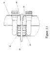
- Fig. 3.1 shows an elevated cut through the integrated vacuum interruption valve 22 with a vertical orifice channel 14 , a horizontal carrier or support channel 21 , the push rod 23 for activating, the valve disk 33 in "vacuum interrupt” position, secured by the vacuum itself within channel 21 .
- Fig. 3.2 shows the same valve 22 in "vacuum conduit” position with the valve disk 33 secured in its place by the force from the coil spring 34 on its one side and the sleeve of the slide pushing 35 on its other side.
- the square valve disk 33 is fixed to its push rod or shaft 23 by press fit.
- the vacuum interruption valve is normally open according to Fig. 3.2.
- the push rod 23 hits upon a body of resistence, i.e. in the shape of a bolt, and the valve closes, according to Fig. 3.1. Now the vacuum in the pertinent vertical channel 14 disappears and the take over of the preforms by the cooling device interface can occur.
- Fig. 4 shows a three-dimensional elevation of the end-of-arm tool-cooling device-interface with the vertical interface bar 41 with its 12 orifices matching the vertical cavity pitch in the mold; the 12 flexible hoses 42 and the horizontal stationary entrance plate 43 , matching the orifice pattern of the cooling device.
- Fig. 5 is an elevated side view of the entire preform handling and cooling system, in a semi-schematic depiction looked at from the injection molding machine, showing the following features and their relations: one of the four vertical orifice channels 14 ; the cooling device's vertical interface bar 41 , the 12 flexible interface hoses 42 linking it with the stationary horizontal entrance plate 43 ; the bottom disk 51 of the indexing cooling drum and the upper disk 52 thereof; 53 some of the altogether 48 vertical cooling tubes, each composed of four parts of plain tubes 531 , and three housings 532 for the previously mentioned secondary retainers; the tapered hood 54 with the connection flange 55 attached to its top for ultimately connecting the cooling drum with the air flow generator, as mentioned before; finally a slide gate type of air flow interruption device 56 for temporarily interrupting the air flow in the fourth section of the cooling drum when the preforms are to be released.
- Fig. 5 also shows the indexing drive 57 for the cooling drum and the support structure or frame 58 of the whole system, and the outfeed conveyor 59 onto which the preforms are to be dropped.
- 510 shows the mounting stand for the side entry take out robot, 511 Its X-Z-axes assembly, with the double arrow indicating the horizontal motion of the X-axis; 512 represents the Z-axis beam, its horizontal motion back and forth being perpendicular to that of the X-axis; 513 finally indicating the servo drive motor for the Z-axis.
- the preforms 11 will be sucked into the flexible hoses 42 ; with their open ends leading, the preforms 11 will locate with their open ends up in the vertical cooling tubes 53 , enhancing the cooling down process of the preforms.
- Fig. 6 is a three-dimensional elevated overview of the entire preform handling and cooling system, according to the invention
- Fig. 7 is a two-dimensional top view of it, corresponding with Fig. 6 but with the tapered hood 56 removed in Fig. 7, in order to offer a plain view of the upper disk 52 of the indexing cooling drum, clearly exposing its four sectors of cooling tubes and their four indexing positions 1, 2, 3 and 4 .
- Figs. 6 and 7 in conjunction enhances the comprehensive understanding of the handling process of the preforms and the underlying intention to optimize the material flow while minimizing the mold intrusion time; minimizing the foot print and travel distances are contributing factors.
- Figs. 6 and 7 enhances the comprehensive understanding of the handling process of the preforms and the underlying intention to optimize the material flow while minimizing the mold intrusion time; minimizing the foot print and travel distances are contributing factors.
- FIGS. 6 and 7 show the following status of the preform handling process the moving platen 61 of the injection molding machine is in "mold open” position and the third mold portion 62 is visible together with a number of cores 63 , with one of the upper two guide bars 64 of the injection molding machine partially removed in order to let the core pattern appear with four vertical columns of 12 cores each, according to our chosen example of 48 cavities; the X-axis 512 has just arrived at its end position for transferring the preforms 11 which are still sitting in vertical orifice channels 14 .
- the preforms will be released from their 12 orifice channel, sucked into the flexible hoses 42 by the conveying and cooling air flow and ultimately transferred into the vertical cooling tubes 53 of the cooling device.
- the remaining preforms 11 in the vertical orifice channels 142, 143 and 144 will be transferred the same way.
- the first channel 141 will be sitting right at the edge of the now closed mold, waiting for the start of the next preform removal cycle, a complete cycle running as follows: upon injection and pre-cooling of the preforms, the mold part 61 opens, moving upwards in Fig.
- the end-of-arm tool is moved into the open mold by fast Z-axis actions to the left; while the X-axis moves towards the exposed preforms still sitting on the cores 63 , the preforms get ejected towards the orifices of the end-of-arm tool at the same time; the transfer of the preforms into the orifices of the vertical channels 14 is assisted by the permanent vacuum air flow in the end-of-arm tool; as soon as all preforms are correctly sitting on their respective orifices, this fact will be signalled by a vacuum sensor and the Z-axis enabled to quickly move out of the mold area, upon which the mold immediately closes again for the next material injection.
- the mold intrusion time is defined as period with the Z-axis starting to move into the open mold until the mold starting to close again and it is expected to take as little time as possible.
- An essential contributing factor to a shortest possible cycle time is the chosen manner of transferring the preforms not in the sequence of first arrival at the interface bar 41 , i.e., with vertical channel 144 but having the X-axis run through to the end of its stroke, coinciding with lining channel 141 up with the interface bar 41 , thus avoiding deceleration of the end-of-arm tool while still being within the mold area.
- the end-of-arm tool automatically ends up in the perfect waiting position for re-entering the mold, which contributes to minimizing the overall cycle time.
- the tapered hood 54 in Fig. 6 has been removed in Fig. 7 in order to show the form indexing drum positions with number 1 showing the preform intake location, number 2 and 3 cooling locations only, and number 4 cooling and release position, while 59 showing the out-feed conveyor.
- Fig. 8 shows another elevated side view of the entire system with the injection molding machine in the background.
- the out-feed conveyor 59 of Fig. 7 is eliminated and replaced by a gaylord 82 on a transport skid 83 , utilizing the fact that the indexing cooling drum is located relatively high up within the entire system.
- a sloped feed out chute 81 facilitates the transfer of the preforms from the cooling drum into gaylord 82 . This measure assists with further reducing both the foot print and the costs of the system as a whole.
- 56 represents the slide gate type of air flow interruption valve, agitated by pneumatic cylinder, solenoid valve controlled, facilitating the release of the preforms at the end of their stay in sector location 4 by briefly interrupting the air flow in the cooling tubes 53 .
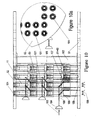
- Figs. 9 and 10 show an elevated front view and an elevated side view, the former partially cut open, of a complete sector of the cooling tubes, particularly to demonstrate the vertical accommodation of the preforms 11 , their handling, cooling, and how they are kept apart to prevent them from binding.
- one sector or battery of cooling tubes 53 consists of two rows of six tubes each, thus accommodating 48 preforms in one battery of tubes 53 .
- the tubes 53 are firmly held in place by the bottom disk 51 and the upper disk 52 , the proper distance between the two disks defined by the center shaft 102 .
- the feed back signal will be provided either by an air blast nozzle with built in dynamic back pressure sensor, or in the case of a pneumatic cylinder, by a reed switch. This measure helps to keep the indexing cooling drum design simple and inexpensive, without wiring and plumbing.
- Figs. 9 and 10 the last layer of preforms can not have arrived yet because their set of secondary retainers 91 are not yet in horizontal position.
- the invention provides a handling and cooling system which takes care of preforms from the mold in the injection molding machine well into the container of transportation for shipping.
- the invention results in a fast-operating work cell with a small footprint and relative low capital and operating costs, to improve the economy of the preform production industry.
Landscapes
- Engineering & Computer Science (AREA)
- Manufacturing & Machinery (AREA)
- Mechanical Engineering (AREA)
- Blow-Moulding Or Thermoforming Of Plastics Or The Like (AREA)
- Processing And Handling Of Plastics And Other Materials For Molding In General (AREA)
Applications Claiming Priority (2)
| Application Number | Priority Date | Filing Date | Title |
|---|---|---|---|
| US09/134,963 US6296473B1 (en) | 1998-08-18 | 1998-08-18 | Handling and cooling system for plastic container preforms |
| US134963 | 1998-08-18 |
Publications (2)
| Publication Number | Publication Date |
|---|---|
| EP0982113A2 true EP0982113A2 (fr) | 2000-03-01 |
| EP0982113A3 EP0982113A3 (fr) | 2001-07-11 |
Family
ID=22465833
Family Applications (1)
| Application Number | Title | Priority Date | Filing Date |
|---|---|---|---|
| EP99306516A Withdrawn EP0982113A3 (fr) | 1998-08-18 | 1999-08-18 | Système de manipulation et de refroidissement pour préformes de récipient en plastique |
Country Status (3)
| Country | Link |
|---|---|
| US (1) | US6296473B1 (fr) |
| EP (1) | EP0982113A3 (fr) |
| CA (1) | CA2280467A1 (fr) |
Cited By (2)
| Publication number | Priority date | Publication date | Assignee | Title |
|---|---|---|---|---|
| CN112192806A (zh) * | 2020-09-28 | 2021-01-08 | 曾镇涛 | 一种塑料注塑机的分级式收料装置 |
| WO2021084094A1 (fr) * | 2019-10-30 | 2021-05-06 | Ma Micro Automation Gmbh | Dispositif de maniement, poste de prélèvement et procédé de maniement de pièces tubulaires ou cupuliformes allongées |
Families Citing this family (13)
| Publication number | Priority date | Publication date | Assignee | Title |
|---|---|---|---|---|
| CA2367525C (fr) * | 1999-04-14 | 2008-09-09 | Pressco Technology Inc. | Procede et dispositif servant a manipuler des unites ejectees d'une machine a mouler par injection |
| ITPN20000036A1 (it) * | 2000-06-06 | 2001-12-06 | Sipa Spa | Impianto e procedimento per la movimentazione e raffreddamento di preforme plastiche |
| CA2464607C (fr) * | 2001-10-24 | 2009-12-22 | Mold-Masters Limited | Refroidissement de preformes apres moulage |
| DE102006028723A1 (de) * | 2006-06-20 | 2008-01-03 | Mht Mold & Hotrunner Technology Ag | Positioniervorrichtung |
| US20080078827A1 (en) * | 2006-09-28 | 2008-04-03 | Geiss David Werner | Process and Communication Interface for Tracking Injection Molded Parts |
| US7905721B2 (en) * | 2007-06-05 | 2011-03-15 | Husky Injection Molding Systems Ltd. | Air source device and a method for use in a molding system |
| GB2469276B (en) * | 2009-04-06 | 2011-03-09 | Constantinos Sideris | Improved injection moulding of plastics articles |
| RU2553389C2 (ru) * | 2013-06-27 | 2015-06-10 | Федеральное государственное бюджетное образовательное учреждение высшего профессионального образования "Петрозаводский государственный университет" | Устройство для работы с микрохирургическими инжекторами |
| CA2955227C (fr) * | 2014-07-17 | 2022-07-26 | Sacmi Imola S.C. | Dispositif pour le dechargement et le stockage de preformes pour la production de recipients en plastique |
| CN109051789A (zh) * | 2018-09-30 | 2018-12-21 | 芜湖顺威精密塑料有限公司 | 一种用于制造贯流端盖的上下料装置 |
| CN109352959B (zh) * | 2018-10-30 | 2024-06-28 | 广州铂特机电设备有限公司 | 高低位接胚机 |
| EP3747310A1 (fr) * | 2019-06-07 | 2020-12-09 | The Procter & Gamble Company | Dispositif de transport de filament |
| US11859067B2 (en) | 2020-03-09 | 2024-01-02 | Nike, Inc. | Footwear mold assembly for injection-molding |
Family Cites Families (6)
| Publication number | Priority date | Publication date | Assignee | Title |
|---|---|---|---|---|
| US4836767A (en) * | 1987-11-25 | 1989-06-06 | Husky Injection Molding System, Ltd. | Swing plate molding machine |
| AU640997B2 (en) | 1990-03-30 | 1993-09-09 | A. K. Technical Laboratory, Inc. | Injection orientation blow molding method |
| US5114327A (en) * | 1991-01-25 | 1992-05-19 | Williamson James T | Rapid cooling apparatus for an injection molding machine |
| US5234328A (en) * | 1991-10-29 | 1993-08-10 | Cbw Automation, Inc. | Retrieval system for removing articles formed by a manufacturing apparatus |
| NL9201738A (nl) * | 1992-10-08 | 1994-05-02 | Inter Tooling Services Bv | Spuitgietinrichting. |
| GB2301308B (en) | 1994-07-28 | 1997-12-17 | Paul Marcus | Parison moulding apparatus and method |
-
1998
- 1998-08-18 US US09/134,963 patent/US6296473B1/en not_active Expired - Fee Related
-
1999
- 1999-08-17 CA CA002280467A patent/CA2280467A1/fr not_active Abandoned
- 1999-08-18 EP EP99306516A patent/EP0982113A3/fr not_active Withdrawn
Cited By (3)
| Publication number | Priority date | Publication date | Assignee | Title |
|---|---|---|---|---|
| WO2021084094A1 (fr) * | 2019-10-30 | 2021-05-06 | Ma Micro Automation Gmbh | Dispositif de maniement, poste de prélèvement et procédé de maniement de pièces tubulaires ou cupuliformes allongées |
| US12269198B2 (en) | 2019-10-30 | 2025-04-08 | Ma Micro Automation Gmbh | Handling device, removal station, and method for handling tubular or elongate bowl-shaped workpieces |
| CN112192806A (zh) * | 2020-09-28 | 2021-01-08 | 曾镇涛 | 一种塑料注塑机的分级式收料装置 |
Also Published As
| Publication number | Publication date |
|---|---|
| CA2280467A1 (fr) | 2000-02-18 |
| US6296473B1 (en) | 2001-10-02 |
| EP0982113A3 (fr) | 2001-07-11 |
Similar Documents
| Publication | Publication Date | Title |
|---|---|---|
| US6296473B1 (en) | Handling and cooling system for plastic container preforms | |
| US5447426A (en) | Take-off plate device | |
| KR100742923B1 (ko) | 플래튼이 장착된 성형 후 냉각 장치 | |
| JP4549846B2 (ja) | 回転および横方向運動を有する成形後冷却装置および方法 | |
| KR100642715B1 (ko) | 회전 이동과 횡방향 이동을 하는 성형후 냉각 장치 및 그방법 | |
| US5569476A (en) | Injection molding machine having a rotatable turret | |
| JPH044129B2 (fr) | ||
| WO2004007170A1 (fr) | Appareil pour manipuler une preforme injectee | |
| US5645865A (en) | Insert molding system | |
| TWI284087B (en) | Post mold cooling and parts retrieval apparatus | |
| US5582845A (en) | Insert molding system incorporating insert detection system | |
| EP0780208B1 (fr) | Système de moulage utilisant un insert | |
| RU2352461C2 (ru) | Устройство для кондиционирования пластмассовых предметов и способ их кондиционирования | |
| US11045986B2 (en) | Injection moulding device for producing parts made of plastic | |
| EP1948416A1 (fr) | Système et procédé pour transférer et refroidir des articles en plastique creux moulés |
Legal Events
| Date | Code | Title | Description |
|---|---|---|---|
| PUAI | Public reference made under article 153(3) epc to a published international application that has entered the european phase |
Free format text: ORIGINAL CODE: 0009012 |
|
| AK | Designated contracting states |
Kind code of ref document: A2 Designated state(s): AT BE CH CY DE DK ES FI FR GB GR IE IT LI LU MC NL PT SE |
|
| AX | Request for extension of the european patent |
Free format text: AL;LT;LV;MK;RO;SI |
|
| PUAL | Search report despatched |
Free format text: ORIGINAL CODE: 0009013 |
|
| AK | Designated contracting states |
Kind code of ref document: A3 Designated state(s): AT BE CH CY DE DK ES FI FR GB GR IE IT LI LU MC NL PT SE |
|
| AX | Request for extension of the european patent |
Free format text: AL;LT;LV;MK;RO;SI |
|
| 17P | Request for examination filed |
Effective date: 20020108 |
|
| AKX | Designation fees paid |
Free format text: AT BE CH CY DE DK ES FI FR GB GR IE IT LI LU MC NL PT SE |
|
| 17Q | First examination report despatched |
Effective date: 20020410 |
|
| STAA | Information on the status of an ep patent application or granted ep patent |
Free format text: STATUS: THE APPLICATION IS DEEMED TO BE WITHDRAWN |
|
| 18D | Application deemed to be withdrawn |
Effective date: 20021022 |