EP0982167A2 - Führungsmechanismus für Fahrzeugsonnendach bestehend aus mindestens zwei Panelen - Google Patents
Führungsmechanismus für Fahrzeugsonnendach bestehend aus mindestens zwei Panelen Download PDFInfo
- Publication number
- EP0982167A2 EP0982167A2 EP99116476A EP99116476A EP0982167A2 EP 0982167 A2 EP0982167 A2 EP 0982167A2 EP 99116476 A EP99116476 A EP 99116476A EP 99116476 A EP99116476 A EP 99116476A EP 0982167 A2 EP0982167 A2 EP 0982167A2
- Authority
- EP
- European Patent Office
- Prior art keywords
- guiding
- panels
- carriages
- carriage
- vehicle
- Prior art date
- Legal status (The legal status is an assumption and is not a legal conclusion. Google has not performed a legal analysis and makes no representation as to the accuracy of the status listed.)
- Granted
Links
- 230000007246 mechanism Effects 0.000 title claims abstract description 37
- 230000008878 coupling Effects 0.000 claims description 21
- 238000010168 coupling process Methods 0.000 claims description 21
- 238000005859 coupling reaction Methods 0.000 claims description 21
- 238000005056 compaction Methods 0.000 claims 2
- 230000008901 benefit Effects 0.000 description 4
- 238000000034 method Methods 0.000 description 4
- 230000008569 process Effects 0.000 description 4
- 230000003993 interaction Effects 0.000 description 3
- 239000002131 composite material Substances 0.000 description 2
- 238000010276 construction Methods 0.000 description 2
- 230000015572 biosynthetic process Effects 0.000 description 1
- 239000000463 material Substances 0.000 description 1
- 230000000284 resting effect Effects 0.000 description 1
Images


Classifications
-
- B—PERFORMING OPERATIONS; TRANSPORTING
- B60—VEHICLES IN GENERAL
- B60J—WINDOWS, WINDSCREENS, NON-FIXED ROOFS, DOORS, OR SIMILAR DEVICES FOR VEHICLES; REMOVABLE EXTERNAL PROTECTIVE COVERINGS SPECIALLY ADAPTED FOR VEHICLES
- B60J7/00—Non-fixed roofs; Roofs with movable panels, e.g. rotary sunroofs
- B60J7/02—Non-fixed roofs; Roofs with movable panels, e.g. rotary sunroofs of sliding type, e.g. comprising guide shoes
- B60J7/04—Non-fixed roofs; Roofs with movable panels, e.g. rotary sunroofs of sliding type, e.g. comprising guide shoes with rigid plate-like element or elements, e.g. open roofs with harmonica-type folding rigid panels
- B60J7/047—Non-fixed roofs; Roofs with movable panels, e.g. rotary sunroofs of sliding type, e.g. comprising guide shoes with rigid plate-like element or elements, e.g. open roofs with harmonica-type folding rigid panels movable to overlapping or nested relationship
Definitions
- the invention concerns a guiding mechanism for a vehicle sunroof consisting of at least two panels with a roof-mounted frame that form an essentially rectangular opening in the vehicle roof with guiding rails that are located on the longitudinal edges of the frame that are essentially parallel with the driving direction of the vehicle and with guiding slides (or carriages) that can be moved forward and backward in the guiding rails, whereas the panels at both ends are connected with one of the guiding carriages each and whereas, preferably, the guiding rails feature at least two parallel guiding tracks.
- Such a guiding mechanism is known from the state of the art of DE 41 23 229 A1, whereby several guiding carriages are located along a guiding rail so they can be moved.
- Each guiding rail features a multitude of oblong connecting link guides and each guiding carriage features recesses so that a sliding block located in a connecting link guide can engage one of the recesses of the guiding carriage.
- one guiding carriage is guided via a sliding block in the multitrack connecting link guide.
- the sliding blocks are disengaged from a drive shaft at varying distances from the forward edge of the opening in the vehicle roof so that the guiding carriages rest in their respective positions. In a fully opened condition the guiding carriages are lined up one behind the other touching each other.
- the guiding mechanisms known as the state of the art have in common that the panels are slanted upwards, each at the same maximal angle. This is based on the use of the same adjustment mechanisms for each panel in order to make smallest spatial dimensions possible for the guiding mechanism. If different angle positions are to be made possible, the space requirement of the corresponding adjustment mechanisms is considerable.
- the invention is based on the problem of configuring and developing the guiding mechanism for a vehicle sunroof as it is known from the state of the art in such a manner that the guiding mechanism requires little space and thus facilitates a large maximal aperture of the vehicle sunroof.
- the guiding carriages of two adjacent panels can be moved into positions in which the guiding carriages are at least partially positioned side by side and the guiding carriages of two adjacent panels, preferably, are positioned each in different guiding tracks.
- the guiding carriages are positioned side by side in particular in the fully open position so that the adjacent guiding carriages are not positioned behind each other and touching each other.
- the maximal aperture of the vehicle sunroof is not limited by the combined length of all of the guiding carriages. Rather, the up-slanted panels are positioned at a distance from each other that is significantly shorter than the length of a guiding carriage. In this way, a significantly larger maximal aperture of the vehicle sunroof has been accomplished in comparison with the state of the art.
- the vehicle sunroof features a sequence of panels for the optional closing or continuous opening of the aperture in the vehicle roof, whereas the panels in the closed position are contiguous and form a composite.
- the composite is opened first the most forward panel slants upward and is then pushed backward. Subsequently the following panel is slanted upward and pushed backward together with the first panel. This process continues until all panels are slanted upward and have been moved backwards as far as possible.
- the closing of the vehicle roof occurs in the reverse sequence, whereby the individual panels are moved into their closing positions and the panels can be swung back into the plane of the vehicle roof.
- the idea on which the invention is based on the one hand consists in realizing through the guiding carriage a lever arm that is sufficient for the stability of the up-slanted panels and on the other hand in positioning the guiding carriages side by side in order to attain a maximal aperture of the vehicle sunroof. Notwithstanding the aforementioned configuration of the invention with the adjacent guiding carriages positioned side by side in different guiding tracks, the task described above can also be solved by positioning the guiding carriages of adjacent panels that are positioned movably in one and the same guiding track and that feature extension elements that are supported by a surface outside the guiding track.
- the entire guiding carriage including the extension element is not contained in the guiding track and the extension element can, by resting on a corresponding surface, absorb the leverage exerted by the panel. If the extension element and the part of the guiding carriage that is contained in the guiding track are now positioned in a staggered formation, adjacent guiding carriages can touch each other, whereas the extension element of the first guiding carriage is positioned to the side of the part of the second guiding carriage that is contained in the guiding track. In this manner, a compact configuration of the guiding carriages is achieved, whereas the combined length of the contiguous guiding carriages is less than the combined length of all of the guiding carriages including the extension elements.
- Each panel in a preferred configuration of the invention, features a separate swiveling mechanism that is independent from the swiveling mechanism of the other panels.
- the larger space required for this is compensated so that in spite of independent adjusting mechanisms for the individual panels, a large maximal aperture of the vehicle sunroof is accomplished.
- the advantage is provided that the panels in the open position can be slanted upward at different angles without increasing the space requirement.
- coupling links between the individual guiding carriages are provided in a preferred configuration.
- coupling elements are proposed, the configuration of which, independently from the staggered positioning of the guiding carriages, has an inventive character.
- coupling elements are provided that function between the guiding carriages that are positioned in one and the same guiding track; i. e., not between each of the two guiding carriages of the two adjacent panels.
- the coupling elements consist on the one hand of recesses and on the other hand of engaging elements, and they engage each other as a consequence of being pushed together when the sunroof is opened.
- the coupling elements disengage at the predetermined positions when the sunroof is closed as a consequence of being pulled apart.
- a forward first guiding carriage is provided that is connected with a drive cable, which engages with all guiding tracks at least partly and features recesses for engaging elements of each following guiding carriage in each guiding track.
- a recess that is positioned at the backside of a forward guiding carriage and a protruding elastic engaging element that is positioned on the front side of the following backward guiding carriage are provided. If in one guiding track two adjacent guiding carriages, i.e. two guiding carriages that are positioned one behind the other, contact each other, the elastic engaging element of the backward guiding carriage engages the corresponding recess of the corresponding forward guiding carriage.
- the invention proposes the inclusion of coupling elements that function between the guiding carriages of adjacent panels, whereas the guiding carriages are positioned in different guiding tracks.
- a link is provided that is positioned on the backside of a forward guiding carriage and that engages at least partially in the guiding track in which the following guiding carriage is positioned featuring a recess.
- a protruding elastic engaging element is provided on the front side of the following backward guiding carriage.
- the elastic engaging element engages the recess in the preceding guiding carriage as soon as the link of the forward guiding carriage touches the front side of the backward guiding carriage.
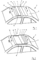
- a vehicle 2 is shown with a vehicle sunroof 4 that features four panels 6, 8, 10, 12 that can be moved in the longitudinal direction of the vehicle 2.
- Panels 6 through 12 are positioned within a roof-mounted frame 14 that form an essentially rectangular opening in the roof 3 of the vehicle 2.
- guiding tracks 16 and 17 are provided that are positioned on the longitudinal edges of the frame 14 that run essentially parallel with the driving direction of the vehicle.
- Both ends of panels 6 through 12 are connected with one each of the guiding carriages 18, 20, 22, and 24 ( Figure 3 through 7), and the guiding carriages 18 through 24 are positioned in the guiding rails 16 and 17 so they can be moved back and forth.
- the vehicle sunroof 4 features a panel that cannot be shifted but that pivots and is configured as an air deflector 26 that is positioned on the forward edge of frame 14.
- FIGs 1 and 2 Two different opening conditions of the vehicle sunroof 4 are illustrated in Figures 1 and 2.
- the vehicle sunroof 4 is only opened far enough that the air deflector 26 is slanted upward in relation to the vehicle roof 3 and that the first panel 6 is also slanted upward relative to the vehicle roof 3 and has moved in the backward direction opposite the driving direction of the vehicle, while the backward panels remain in the completely closed positions.
- the vehicle sunroof 4 shown in Figure 2 is in its maximal open condition with all panels 6, 8, 10 and 12 slanted upward and backward as far as possible relative to the vehicle roof opposite the driving direction.
- the guiding mechanism of the present invention that makes this position possible is explained in more detail with Figures 3 through 10.
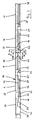
- the configuration of the guiding carriages 18-24 is shown with the corresponding panels 6-12 and with the air deflector 26 for the closed position of the vehicle sunroof 4.
- the guiding rail 16 features two parallel guiding tracks 28 and 30.
- the guiding carriages 18/20, 20/22 and 22/24 of two adjacent panels 6/8, 8/10 and 10/12 each are alternatingly positioned in both guiding tracks 28 and 30.
- the guiding carriages 18 and 22 are positioned in guiding track 28 and the guiding carriages 20 and 24 are positioned in guiding track 30, as seen in Figure 4.
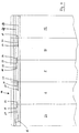
- the sunroof is shown in its fully open position.
- the guiding carriages 18-24 can be moved into positions in which the guiding carriages 18, 22, and 20, 24 are at least partially positioned side by side.
- the embodiment shows that the guiding carriages 18 and 22 positioned in guiding track 28 as well as the guiding carriages 20 and 24 in guiding track 30 touch each other, whereas the pairs of the guiding carriages 18, 22 and 20, 24 are positioned staggered against each other by essentially half the length of a guiding carriage 18 through 24.
- a maximal aperture of the vehicle sunroof 4 is guaranteed with minimal required space.
- the panels 6-12 are connected with the guiding carriages 18-24 by way of the pivoting elements 32, 34, 36 and 38.
- the panels 6-12 are permanently attached to the pivoting elements 32-38, while the pivoting elements 32-38 are connected, via a separate connecting link each, to the guiding carriages 18-24 in a manner that permits them to pivot.
- the pivoting elements 32-38 are forced by the connecting link to conduct a pivoting movement so that the panels 6-12 are positioned as predetermined in a predetermined angle relative to the vehicle roof 3.
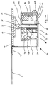
- FIG. 8-10 each show a cross section at the positions marked in Figure 3 with VIII, IX and X.
- the guiding rail 16 is connected with the vehicle roof 3 along an edge 40 that is configured as an angle along the frame 14.
- the guiding rail 16 further features two essentially symmetrically configured areas that are parallel with each other and that form the two guiding tracks 28 and 30 that are positioned opposite each other.
- oblong connecting link elements 42 and 44 are positioned that are e. g. made out of plastic and in which for each guiding carriage 18/22 or 20/24 a connecting link guide 46 or 48 is provided.
- the extension of the connecting link guides 46 and 48 can be best seen in Figure 6.
- the guiding carriage 22 is adjacent to the connecting link element 42 in the guiding track 28, positioned along the connecting link element 42 in a manner that makes it movable back and forth.
- Guiding carriage 22 features a connecting link guide 50 and it can be seen in Figures 3, 5 and 8.
- the pivoting element 36 that is permanently attached to the panel 10 is located on the side of the guiding carriage 22 that faces the connecting link element 42.
- the pivoting element 36 features an integrally configured sliding block 52 that extends through the connecting link guide 50 of the guiding carriage 22 to connecting link guide 46 that is part of the connecting link element 42 and with which it engages.
- the guiding carriage 22 features a second sliding block 54 that is integrally configured offset toward the back and that engages a connecting link guide 56 that is configured within the pivoting element 36.
- the shape and form of the connecting link guide 56 can be seen in Figures 3, 5 and 6.
- the first sliding block 52 of the pivoting element 36 is located in the forward and upward pointing end of the connecting link guide 48 so that through the interaction between the second sliding block 54 and the connecting link guide 56, the pivoting element assumes an essentially horizontal position. Panel 10 that is attached to the pivoting element is thus positioned in an essentially horizontal position.
- the first sliding block 52 is moved downward by connecting link guide 48, which generates a relative movement between the pivoting element 36 and the guiding carriage 22, during which, due to the form of the connecting link guide 50, the front end of the pivoting element 36 is adjusted downward.
- the individually selectable slanting mechanism for each of the panels 6 through 12 does not limit the maximal possible aperture of the vehicle sunroof, since - as described earlier - in the open condition, the guiding carriages 18/22 and 20/24 are positioned side by side in the two adjacent guiding tracks 28 and 30.
- each coupling element features recesses 70, 72, 74 and engaging elements 58, 60, 62, 64.
- a first front guiding carriage 66 is provided for the opening and closing of the vehicle sunroof.
- This guiding carriage 66 is connected with a drive cable that runs through a channel 68 (see Figures 8-10).
- the drive cable is connected with an adjusting mechanism inside the vehicle so that the vehicle sunroof 4 can be opened and closed by the user.
- the forward first guiding carriage 66 engages in both guiding tracks 28 and 30, as shown in Figures 4 and 7.
- the forward first guiding carriage 66 features two recesses 70 with which the engaging elements 58 and 60 (described in more detail below) of the following guiding carriages 18 and 20 of each guiding track 28 and 30 engage thus implementing the coupling.
- the guiding carriages 18 and 20 feature recesses 72 and 74 in the back that face in the driving direction, whereas the recesses 70 through 74 are configured in a similar fashion.
- the engaging elements 58-64 are configured as leaf springs at the front side of the guiding carriages 18-24.
- the engaging element 64 features a front end 80 that protrudes upward. Further, the engaging element 64 features a downward-directed catch nose 82 and touches under prestress the bottom surface 84 of the guiding track 30. In the position of the vehicle sunroof shown in Figures 3 or 8-10, the catch nose 82 engages a notch 92 in the bottom surface 84 of the guiding track 30 through which the coupling between the guiding carriage 24 with the guiding track 30 is implemented. Further recesses 86, 88 and 92 configured for the guiding carriages 18, 20 and 22 in the bottom surfaces 64 and 65 of the corresponding guiding tracks 28 and 30 in particular are shown in Figure 7.
- the front end 80 of the engaging element 64 engages the recess 74 of the guiding carriage 20 when the vehicle sunroof is compacted during the opening process.
- the engaging element 64 that is configured as a leaf spring is lifted up when the guiding carriage 20 is pushed backwards, i. e., up to the availability of the bottom surface 84 of the guiding track 30.
- the catch nose 82 now no longer engages the recess 92.
- the protruding end of the engaging element 64 engages the recess 92 in the predefined position with the catch nose 82 and the protruding end 80 disengages the recess 78.
- Coupling elements 58 and 64 are configured in a similar fashion in order to function between two guiding carriages 18-24 or 66.
Landscapes
- Engineering & Computer Science (AREA)
- Mechanical Engineering (AREA)
- Seal Device For Vehicle (AREA)
- Body Structure For Vehicles (AREA)
- Power-Operated Mechanisms For Wings (AREA)
- Control Of Position, Course, Altitude, Or Attitude Of Moving Bodies (AREA)
- Support Devices For Sliding Doors (AREA)
Applications Claiming Priority (2)
| Application Number | Priority Date | Filing Date | Title |
|---|---|---|---|
| DE29815104U DE29815104U1 (de) | 1998-08-22 | 1998-08-22 | Führungsmechanik für ein aus mindestens zwei Lamellen bestehendes Fahrzeugschiebedach |
| DE29815104U | 1998-08-22 |
Publications (3)
| Publication Number | Publication Date |
|---|---|
| EP0982167A2 true EP0982167A2 (de) | 2000-03-01 |
| EP0982167A3 EP0982167A3 (de) | 2000-06-28 |
| EP0982167B1 EP0982167B1 (de) | 2005-10-19 |
Family
ID=8061661
Family Applications (1)
| Application Number | Title | Priority Date | Filing Date |
|---|---|---|---|
| EP99116476A Expired - Lifetime EP0982167B1 (de) | 1998-08-22 | 1999-08-22 | Führungsmechanismus für Fahrzeugsonnendach bestehend aus mindestens zwei Panelen |
Country Status (5)
| Country | Link |
|---|---|
| US (1) | US6264270B1 (de) |
| EP (1) | EP0982167B1 (de) |
| JP (1) | JP2000219044A (de) |
| AT (1) | ATE307038T1 (de) |
| DE (2) | DE29815104U1 (de) |
Cited By (1)
| Publication number | Priority date | Publication date | Assignee | Title |
|---|---|---|---|---|
| CN102133853A (zh) * | 2010-01-26 | 2011-07-27 | 银娜珐天窗系统集团股份有限公司 | 车顶组件以及安装滤网构件的方法 |
Families Citing this family (6)
| Publication number | Priority date | Publication date | Assignee | Title |
|---|---|---|---|---|
| DE29902662U1 (de) * | 1999-02-15 | 2000-07-06 | Meritor Automotive GmbH, 60314 Frankfurt | Verstellvorrichtung für ein Multispoilerdach für Fahrzeuge |
| DE10063055B4 (de) * | 2000-12-18 | 2005-04-07 | Webasto Ag | Fahrzeugdach mit zwei verstellbaren Deckeln |
| DE10133436A1 (de) | 2001-07-10 | 2003-01-30 | Arvinmeritor Gmbh | Modul, insbesondere Schiebedachmodul für ein Fahrzeug |
| US20080081148A1 (en) * | 2006-09-13 | 2008-04-03 | Kenneth Bond | Panel having a frame bonded thereto |
| JP5029111B2 (ja) * | 2007-04-13 | 2012-09-19 | トヨタ紡織株式会社 | 車両ルーフ構造 |
| CN110962730A (zh) * | 2018-09-30 | 2020-04-07 | 苏州迪芬德物联网科技有限公司 | 一种风道风压式隔温式仓储冷藏物流车 |
Citations (4)
| Publication number | Priority date | Publication date | Assignee | Title |
|---|---|---|---|---|
| DE4123229A1 (de) | 1991-07-13 | 1993-01-14 | Webasto Ag Fahrzeugtechnik | Fahrzeugdach mit einer folge von lamellen |
| GB2258848A (en) | 1991-08-21 | 1993-02-24 | Webasto Karosseriesysteme | Opening vehicle roof. |
| DE4415649C1 (de) | 1994-05-04 | 1995-06-08 | Daimler Benz Ag | Lamellendach für ein Kraftfahrzeug |
| DE19608916C1 (de) | 1996-03-07 | 1997-04-17 | Webasto Karosseriesysteme | Fahrzeugdach mit einer Folge von ausstellbaren Deckelelementen |
Family Cites Families (67)
| Publication number | Priority date | Publication date | Assignee | Title |
|---|---|---|---|---|
| US1387062A (en) | 1921-08-09 | Am-cerculatiolt-controllotg device fob automobile-radiators | ||
| US1272983A (en) | 1918-02-26 | 1918-07-16 | Salvatore Guzzo Menzo | Furniture construction. |
| US1787451A (en) | 1929-12-09 | 1931-01-06 | Nat Lock Washer Co | Curtain fixture |
| GB349172A (en) * | 1930-03-08 | 1931-05-28 | Duple Bodies And Motors Ltd | Improvements in or relating to hoods for vehicles |
| US2338309A (en) | 1939-05-03 | 1944-01-04 | Briggs Mfg Co | Vehicle body |
| US2263216A (en) * | 1939-05-19 | 1941-11-18 | Latchford John Henry | Motor car body |
| GB573355A (en) | 1943-12-10 | 1945-11-16 | Edgar Walter Neale | Improvements relating to slidable roofs for motor vehicle saloon bodies |
| US2516702A (en) | 1946-12-26 | 1950-07-25 | American Machine & Metals | Damper and heating unit |
| US2497419A (en) | 1946-12-30 | 1950-02-14 | Victor Tool & Machine Corp | Awning |
| US2853340A (en) | 1956-12-17 | 1958-09-23 | Vilas D Hershberger | Telescoping roof for trucks and trailers |
| US3906669A (en) | 1973-03-02 | 1975-09-23 | Lockheed Aircraft Corp | Window assembly |
| US3845591A (en) | 1973-06-11 | 1974-11-05 | J Stine | Expandable cover system |
| CH571641A5 (en) | 1974-05-14 | 1976-01-15 | Baumann & Co G | Hinged-slatted venetian draw-blind - with bottom slat angled when lowered for progressive angled overlap on raising |
| US4068699A (en) | 1975-10-14 | 1978-01-17 | Tucker Lyndell L | Fireplace closure |
| US4286821A (en) | 1980-03-26 | 1981-09-01 | Herbert Cooper | Automobile body with a retractable hard top roof |
| DE3020675C2 (de) | 1980-05-30 | 1987-01-02 | Rockwell Golde Gmbh, 6000 Frankfurt | Schiebe-Hebe-Dach für Kraftfahrzeuge |
| DE3116641A1 (de) * | 1981-04-27 | 1982-11-18 | Sekura Komfortkabinen GmbH, 6252 Diez | Fahrerschutzkabine fuer fahrzeuge |
| JPS5825722U (ja) | 1981-08-14 | 1983-02-18 | アイシン精機株式会社 | 自動車ル−フの窓用サンシエ−ド |
| US4403805A (en) | 1982-01-06 | 1983-09-13 | General Motors Corporation | Sliding sunroof with power operated ventilator |
| JPS58157824U (ja) | 1982-04-16 | 1983-10-21 | ダイキヨ−・ベバスト株式会社 | 乗物の屋根窓 |
| DE3311452A1 (de) | 1982-04-16 | 1983-10-20 | Webasto-Werk W. Baier GmbH & Co, 8035 Gauting | Hebeschiebedach |
| DE3218209C2 (de) | 1982-05-14 | 1986-10-16 | Webasto-Werk W. Baier GmbH & Co, 8035 Gauting | Schiebehebedach für Kraftfahrzeuge |
| DE3316739A1 (de) | 1982-07-16 | 1984-01-19 | Webasto-Werk W. Baier GmbH & Co, 8035 Gauting | Kraftfahrzeugdach |
| NL182461C (nl) | 1982-12-30 | 1988-03-16 | Vermeulen Hollandia Octrooien | Schuifdak voor een voertuig. |
| NL8301610A (nl) | 1983-05-06 | 1984-12-03 | Vermeulen Hollandia Octrooien | Open dakconstructie voor een voertuig. |
| NL186303C (nl) | 1983-05-06 | 1990-11-01 | Vermeulen Hollandia Octrooien | Dakconstructie voor een voertuig, waarbij een stijf paneel onder een vast dak en daarboven in een ventilatiestand is te brengen. |
| DE3442615C2 (de) | 1984-11-22 | 1986-10-02 | Daimler-Benz Ag, 7000 Stuttgart | Schiebehebedach |
| DE3442631A1 (de) | 1984-11-22 | 1986-05-22 | Webasto-Werk W. Baier GmbH & Co, 8035 Gauting | Schiebehebedach |
| DE3506460A1 (de) | 1985-02-23 | 1986-08-28 | Andreas 4040 Neuss Krüll | Rolladen oder rollbahn aus einzellamellen |
| GB8506558D0 (en) | 1985-03-13 | 1985-04-17 | Britax Weathershields | Opening roof for motor vehicle |
| DE3524840A1 (de) | 1985-07-11 | 1987-01-15 | Weinsberg Karosseriewerke | Flachbauendes schiebedach fuer kraftfahrzeuge |
| DE3572330D1 (en) | 1985-09-05 | 1989-09-21 | Vermeulen Hollandia Octrooien | Open roof-construction for a vehicle |
| DE3545870C2 (de) | 1985-12-23 | 1993-12-09 | Webasto Werk Baier Kg W | Fahrzeugschiebedach |
| US4869548A (en) | 1986-03-10 | 1989-09-26 | Ohi Seisakusho Company, Limited | Sunroof apparatus for vehicle |
| DE3715268A1 (de) | 1986-07-12 | 1988-01-21 | Webasto Werk Baier Kg W | Betaetigungsvorrichtung fuer ein fahrzeugdach |
| JPH0428816Y2 (de) | 1987-01-22 | 1992-07-14 | ||
| JPH0341940Y2 (de) | 1987-01-28 | 1991-09-03 | ||
| US4852938A (en) | 1987-02-05 | 1989-08-01 | Nissan Design International, Inc. | Transparent roof convertible automobile with retractable sunshade |
| US4982995A (en) | 1987-07-17 | 1991-01-08 | Ohi Seisakusho Co., Ltd. | Lid regulating device for sun roof structure |
| DE3737725C1 (de) * | 1987-11-06 | 1988-12-22 | Ford Werke Ag | Ausstell-Schiebedach fuer Kraftfahrzeuge |
| NL8801028A (nl) | 1988-04-21 | 1989-11-16 | Vermeulen Hollandia Octrooien | Open dakconstructie voor een voertuig. |
| US4893868A (en) | 1988-07-18 | 1990-01-16 | Cars & Concepts, Inc. | Vehicle door-to-door sunroof assembly |
| US5026113A (en) | 1988-09-09 | 1991-06-25 | Sky-Top Sunroofs Ltd. | Sliding and venting sunroof |
| NL8802552A (nl) | 1988-10-17 | 1990-05-16 | Vermeulen Hollandia Octrooien | Open-dakconstructie voor een voertuig. |
| DE3903035A1 (de) | 1989-02-02 | 1990-08-09 | Webasto Ag Fahrzeugtechnik | Fahrzeugdach mit einem mittels eines deckels verschliessbaren dachausschnitt |
| JPH085319B2 (ja) | 1989-02-27 | 1996-01-24 | 日産自動車株式会社 | 自動車のサンルーフ構造 |
| FR2648403A1 (fr) | 1989-06-15 | 1990-12-21 | Heuliez Henri France Design | Mecanisme d'ouverture, de fermeture et d'entrebaillement d'un panneau mobile par rapport a une surface fixe, notamment pour toit ouvrant d'un vehicule automobile |
| DE3920909A1 (de) | 1989-06-26 | 1991-01-03 | Farmont Produktion | Schiebedach |
| US5197779A (en) | 1989-06-27 | 1993-03-30 | Mazda Motor Corporation | Power sliding sunroof |
| DE3930756A1 (de) | 1989-09-14 | 1991-03-28 | Webasto Ag Fahrzeugtechnik | Schiebehebedach fuer fahrzeuge |
| JPH03125628A (ja) | 1989-10-09 | 1991-05-29 | Daikyo Webasto Co Ltd | サンルーフのトリム昇降装置 |
| DE4129860C1 (de) | 1991-09-07 | 1992-09-17 | Webasto Ag Fahrzeugtechnik, 8035 Stockdorf, De | |
| DE59204071D1 (de) | 1992-02-18 | 1995-11-23 | Webasto Karosseriesysteme | Kurbelantrieb für ein verstellbares Teil eines Fahrzeugdaches. |
| DE4227402C1 (de) | 1992-08-19 | 1994-01-13 | Webasto Karosseriesysteme | Fahrzeugdach |
| DE4227400C2 (de) | 1992-08-19 | 1997-07-17 | Webasto Karosseriesysteme | Schiebedach |
| DE4233507C1 (de) | 1992-10-06 | 1993-11-11 | Webasto Karosseriesysteme | Fahrzeugdach mit einer Folge von Lamellen |
| DE9301259U1 (de) | 1993-01-29 | 1993-05-19 | Koch, Hubert, 85716 Unterschleißheim | Schutzkontaktvorrichtung für Schließkanten |
| DE9302762U1 (de) | 1993-02-25 | 1993-04-15 | Kelm, Eckehart, 8031 Gilching | Verstelleinrichtung für ein Hebeschiebedach |
| US5287655A (en) | 1993-03-01 | 1994-02-22 | Metal Industries, Inc. | Roller arrangement for sliding panels |
| DE9306187U1 (de) | 1993-04-23 | 1993-11-25 | Kelm, Eckehart, 82205 Gilching | Schiebedach |
| JPH0740746A (ja) * | 1993-07-29 | 1995-02-10 | Aisin Seiki Co Ltd | 車両用サンルーフ装置のチエツク機構 |
| DE4329580C1 (de) * | 1993-09-02 | 1994-11-03 | Webasto Karosseriesysteme | Fahrzeugdach mit einer Folge von Lamellen |
| DE4407286C1 (de) * | 1994-03-04 | 1995-05-04 | Webasto Karosseriesysteme | Fahrzeugdach mit einer Folge von Lamellen |
| DE19503786A1 (de) * | 1995-02-06 | 1996-08-08 | Karl Bauhof | Schiebedach dessen Deckel auch während der Fahrt in eine im Heckraum befindliche Deckel-Aufnahmekassette ein und ausfahrbar sind |
| DE9412816U1 (de) | 1994-08-09 | 1995-12-07 | Westmont Technik GmbH & Co. KG, 40474 Düsseldorf | Führung für Lamellen |
| DE9412811U1 (de) | 1994-08-09 | 1995-12-07 | Westmont Technik GmbH & Co. KG, 40474 Düsseldorf | Sonnenschutzvorrichtung, insbesondere für lichtdurchlässige Sonnendächer |
| US5816647A (en) | 1996-03-27 | 1998-10-06 | Westmont Technik Gmbh & Co. Kg | Louver arrangement for vehicle sun roofs, especially transparent ones |
-
1998
- 1998-08-22 DE DE29815104U patent/DE29815104U1/de not_active Expired - Lifetime
-
1999
- 1999-08-19 US US09/377,086 patent/US6264270B1/en not_active Expired - Fee Related
- 1999-08-20 JP JP11233937A patent/JP2000219044A/ja active Pending
- 1999-08-22 EP EP99116476A patent/EP0982167B1/de not_active Expired - Lifetime
- 1999-08-22 AT AT99116476T patent/ATE307038T1/de not_active IP Right Cessation
- 1999-08-22 DE DE69927757T patent/DE69927757T2/de not_active Expired - Fee Related
Patent Citations (4)
| Publication number | Priority date | Publication date | Assignee | Title |
|---|---|---|---|---|
| DE4123229A1 (de) | 1991-07-13 | 1993-01-14 | Webasto Ag Fahrzeugtechnik | Fahrzeugdach mit einer folge von lamellen |
| GB2258848A (en) | 1991-08-21 | 1993-02-24 | Webasto Karosseriesysteme | Opening vehicle roof. |
| DE4415649C1 (de) | 1994-05-04 | 1995-06-08 | Daimler Benz Ag | Lamellendach für ein Kraftfahrzeug |
| DE19608916C1 (de) | 1996-03-07 | 1997-04-17 | Webasto Karosseriesysteme | Fahrzeugdach mit einer Folge von ausstellbaren Deckelelementen |
Cited By (2)
| Publication number | Priority date | Publication date | Assignee | Title |
|---|---|---|---|---|
| CN102133853A (zh) * | 2010-01-26 | 2011-07-27 | 银娜珐天窗系统集团股份有限公司 | 车顶组件以及安装滤网构件的方法 |
| CN102133853B (zh) * | 2010-01-26 | 2015-01-07 | 银娜珐天窗系统集团股份有限公司 | 车顶组件以及安装滤网构件的方法 |
Also Published As
| Publication number | Publication date |
|---|---|
| US6264270B1 (en) | 2001-07-24 |
| JP2000219044A (ja) | 2000-08-08 |
| DE69927757D1 (de) | 2005-11-24 |
| ATE307038T1 (de) | 2005-11-15 |
| DE29815104U1 (de) | 1999-12-30 |
| DE69927757T2 (de) | 2006-07-06 |
| EP0982167A3 (de) | 2000-06-28 |
| EP0982167B1 (de) | 2005-10-19 |
Similar Documents
| Publication | Publication Date | Title |
|---|---|---|
| US4601512A (en) | Open roof-construction for a vehicle | |
| US5601330A (en) | Vehicle roof with two cover elements | |
| US7950733B2 (en) | Mechanism for an adjustable body component of a vehicle | |
| JP4797091B2 (ja) | サンルーフ装置におけるシェードパネルの連動機構 | |
| US7810879B2 (en) | Vehicle sun roof system | |
| US6527337B2 (en) | Sliding roof cover of a motor vehicle roof and a motor vehicle roof with movable sliding roof covers | |
| US4685724A (en) | Sliding roof for vehicles | |
| EP1500540B1 (de) | Öffnungsfähige Dachkonstruktion für ein Fahrzeug | |
| EP1009644B2 (de) | Verfahren zum öffnen und schliessen einer öffnungsfähigen dachherstellung für ein fahrzeug mit einer öffnung im festen dach, sowie solche öffnungsfähige dachherstellung | |
| GB2161439A (en) | Vehicle roofs | |
| CN114845893B (zh) | 包括具有两个运动单元的车顶打开系统的车顶 | |
| EP0982167B1 (de) | Führungsmechanismus für Fahrzeugsonnendach bestehend aus mindestens zwei Panelen | |
| CN102348565B (zh) | 具有控制滑块的顶盖元件载体 | |
| EP1070616B1 (de) | Konstruktion eines öffnungsfähigen Fahrzeugdaches | |
| EP1046529B1 (de) | Konstruktion eines öffnungsfähigen Fahrzeugdaches | |
| US6877799B2 (en) | Openable motor vehicle roof | |
| US4895410A (en) | Sliding and lifting roofs | |
| JP4105637B2 (ja) | 車両用の屋根組立体 | |
| CN111137118A (zh) | 用于车辆的车顶系统 | |
| US6419309B1 (en) | Open roof construction for a vehicle | |
| EP0555977B1 (de) | Fahrzeug-Sonnendach | |
| CN102341256A (zh) | 具有用于顶盖元件的驱动滑架的车顶 | |
| EP1331119B1 (de) | Fahrzeug mit Hebeschiebedach | |
| EP0244110A2 (de) | Öffnendes Dach eines Kraftfahrzeuges | |
| EP1964702B1 (de) | Offene Dachkonstruktion für ein Fahrzeug |
Legal Events
| Date | Code | Title | Description |
|---|---|---|---|
| PUAI | Public reference made under article 153(3) epc to a published international application that has entered the european phase |
Free format text: ORIGINAL CODE: 0009012 |
|
| AK | Designated contracting states |
Kind code of ref document: A2 Designated state(s): AT BE CH CY DE DK ES FI FR GB GR IE IT LI LU MC NL PT SE |
|
| AX | Request for extension of the european patent |
Free format text: AL;LT;LV;MK;RO;SI |
|
| PUAL | Search report despatched |
Free format text: ORIGINAL CODE: 0009013 |
|
| AK | Designated contracting states |
Kind code of ref document: A3 Designated state(s): AT BE CH CY DE DK ES FI FR GB GR IE IT LI LU MC NL PT SE |
|
| AX | Request for extension of the european patent |
Free format text: AL;LT;LV;MK;RO;SI |
|
| 17P | Request for examination filed |
Effective date: 20001109 |
|
| AKX | Designation fees paid |
Free format text: AT BE CH CY DE DK ES FI FR GB GR IE IT LI LU MC NL PT SE |
|
| 17Q | First examination report despatched |
Effective date: 20040419 |
|
| GRAP | Despatch of communication of intention to grant a patent |
Free format text: ORIGINAL CODE: EPIDOSNIGR1 |
|
| GRAS | Grant fee paid |
Free format text: ORIGINAL CODE: EPIDOSNIGR3 |
|
| RAP1 | Party data changed (applicant data changed or rights of an application transferred) |
Owner name: ARVINMERITOR GMBH |
|
| GRAA | (expected) grant |
Free format text: ORIGINAL CODE: 0009210 |
|
| AK | Designated contracting states |
Kind code of ref document: B1 Designated state(s): AT BE CH CY DE DK ES FI FR GB GR IE IT LI LU MC NL PT SE |
|
| PG25 | Lapsed in a contracting state [announced via postgrant information from national office to epo] |
Ref country code: LI Free format text: LAPSE BECAUSE OF FAILURE TO SUBMIT A TRANSLATION OF THE DESCRIPTION OR TO PAY THE FEE WITHIN THE PRESCRIBED TIME-LIMIT Effective date: 20051019 Ref country code: FI Free format text: LAPSE BECAUSE OF FAILURE TO SUBMIT A TRANSLATION OF THE DESCRIPTION OR TO PAY THE FEE WITHIN THE PRESCRIBED TIME-LIMIT Effective date: 20051019 Ref country code: CH Free format text: LAPSE BECAUSE OF FAILURE TO SUBMIT A TRANSLATION OF THE DESCRIPTION OR TO PAY THE FEE WITHIN THE PRESCRIBED TIME-LIMIT Effective date: 20051019 Ref country code: BE Free format text: LAPSE BECAUSE OF FAILURE TO SUBMIT A TRANSLATION OF THE DESCRIPTION OR TO PAY THE FEE WITHIN THE PRESCRIBED TIME-LIMIT Effective date: 20051019 Ref country code: AT Free format text: LAPSE BECAUSE OF FAILURE TO SUBMIT A TRANSLATION OF THE DESCRIPTION OR TO PAY THE FEE WITHIN THE PRESCRIBED TIME-LIMIT Effective date: 20051019 |
|
| REG | Reference to a national code |
Ref country code: GB Ref legal event code: FG4D |
|
| REG | Reference to a national code |
Ref country code: CH Ref legal event code: EP |
|
| REG | Reference to a national code |
Ref country code: IE Ref legal event code: FG4D |
|
| REF | Corresponds to: |
Ref document number: 69927757 Country of ref document: DE Date of ref document: 20051124 Kind code of ref document: P |
|
| PG25 | Lapsed in a contracting state [announced via postgrant information from national office to epo] |
Ref country code: SE Free format text: LAPSE BECAUSE OF FAILURE TO SUBMIT A TRANSLATION OF THE DESCRIPTION OR TO PAY THE FEE WITHIN THE PRESCRIBED TIME-LIMIT Effective date: 20060119 Ref country code: GR Free format text: LAPSE BECAUSE OF FAILURE TO SUBMIT A TRANSLATION OF THE DESCRIPTION OR TO PAY THE FEE WITHIN THE PRESCRIBED TIME-LIMIT Effective date: 20060119 Ref country code: DK Free format text: LAPSE BECAUSE OF FAILURE TO SUBMIT A TRANSLATION OF THE DESCRIPTION OR TO PAY THE FEE WITHIN THE PRESCRIBED TIME-LIMIT Effective date: 20060119 |
|
| PG25 | Lapsed in a contracting state [announced via postgrant information from national office to epo] |
Ref country code: ES Free format text: LAPSE BECAUSE OF FAILURE TO SUBMIT A TRANSLATION OF THE DESCRIPTION OR TO PAY THE FEE WITHIN THE PRESCRIBED TIME-LIMIT Effective date: 20060130 |
|
| PG25 | Lapsed in a contracting state [announced via postgrant information from national office to epo] |
Ref country code: PT Free format text: LAPSE BECAUSE OF FAILURE TO SUBMIT A TRANSLATION OF THE DESCRIPTION OR TO PAY THE FEE WITHIN THE PRESCRIBED TIME-LIMIT Effective date: 20060320 |
|
| REG | Reference to a national code |
Ref country code: CH Ref legal event code: PL |
|
| ET | Fr: translation filed | ||
| PG25 | Lapsed in a contracting state [announced via postgrant information from national office to epo] |
Ref country code: IE Free format text: LAPSE BECAUSE OF NON-PAYMENT OF DUE FEES Effective date: 20060822 |
|
| PLBE | No opposition filed within time limit |
Free format text: ORIGINAL CODE: 0009261 |
|
| STAA | Information on the status of an ep patent application or granted ep patent |
Free format text: STATUS: NO OPPOSITION FILED WITHIN TIME LIMIT |
|
| PG25 | Lapsed in a contracting state [announced via postgrant information from national office to epo] |
Ref country code: MC Free format text: LAPSE BECAUSE OF NON-PAYMENT OF DUE FEES Effective date: 20060831 |
|
| PGFP | Annual fee paid to national office [announced via postgrant information from national office to epo] |
Ref country code: IT Payment date: 20060831 Year of fee payment: 8 |
|
| PGFP | Annual fee paid to national office [announced via postgrant information from national office to epo] |
Ref country code: DE Payment date: 20060914 Year of fee payment: 8 |
|
| PGFP | Annual fee paid to national office [announced via postgrant information from national office to epo] |
Ref country code: NL Payment date: 20060924 Year of fee payment: 8 |
|
| 26N | No opposition filed |
Effective date: 20060720 |
|
| GBPC | Gb: european patent ceased through non-payment of renewal fee |
Effective date: 20060822 |
|
| REG | Reference to a national code |
Ref country code: IE Ref legal event code: MM4A |
|
| PG25 | Lapsed in a contracting state [announced via postgrant information from national office to epo] |
Ref country code: GB Free format text: LAPSE BECAUSE OF NON-PAYMENT OF DUE FEES Effective date: 20060822 |
|
| PG25 | Lapsed in a contracting state [announced via postgrant information from national office to epo] |
Ref country code: NL Free format text: LAPSE BECAUSE OF NON-PAYMENT OF DUE FEES Effective date: 20080301 |
|
| NLV4 | Nl: lapsed or anulled due to non-payment of the annual fee |
Effective date: 20080301 |
|
| REG | Reference to a national code |
Ref country code: FR Ref legal event code: ST Effective date: 20080430 |
|
| PG25 | Lapsed in a contracting state [announced via postgrant information from national office to epo] |
Ref country code: LU Free format text: LAPSE BECAUSE OF NON-PAYMENT OF DUE FEES Effective date: 20060822 Ref country code: DE Free format text: LAPSE BECAUSE OF NON-PAYMENT OF DUE FEES Effective date: 20080301 |
|
| PG25 | Lapsed in a contracting state [announced via postgrant information from national office to epo] |
Ref country code: FR Free format text: LAPSE BECAUSE OF NON-PAYMENT OF DUE FEES Effective date: 20070831 |
|
| PGFP | Annual fee paid to national office [announced via postgrant information from national office to epo] |
Ref country code: FR Payment date: 20060927 Year of fee payment: 8 |
|
| PG25 | Lapsed in a contracting state [announced via postgrant information from national office to epo] |
Ref country code: CY Free format text: LAPSE BECAUSE OF FAILURE TO SUBMIT A TRANSLATION OF THE DESCRIPTION OR TO PAY THE FEE WITHIN THE PRESCRIBED TIME-LIMIT Effective date: 20051019 |
|
| PG25 | Lapsed in a contracting state [announced via postgrant information from national office to epo] |
Ref country code: IT Free format text: LAPSE BECAUSE OF NON-PAYMENT OF DUE FEES Effective date: 20070822 |