EP0982172B1 - Régulateur de vitesse automatique avec régulation de la distance entre deux véhicules - Google Patents
Régulateur de vitesse automatique avec régulation de la distance entre deux véhicules Download PDFInfo
- Publication number
- EP0982172B1 EP0982172B1 EP99116561A EP99116561A EP0982172B1 EP 0982172 B1 EP0982172 B1 EP 0982172B1 EP 99116561 A EP99116561 A EP 99116561A EP 99116561 A EP99116561 A EP 99116561A EP 0982172 B1 EP0982172 B1 EP 0982172B1
- Authority
- EP
- European Patent Office
- Prior art keywords
- inter
- vehicle
- vehicle distance
- vehicular velocity
- velocity
- Prior art date
- Legal status (The legal status is an assumption and is not a legal conclusion. Google has not performed a legal analysis and makes no representation as to the accuracy of the status listed.)
- Expired - Lifetime
Links
- 230000004044 response Effects 0.000 claims description 64
- 238000013016 damping Methods 0.000 claims description 25
- 230000006870 function Effects 0.000 claims description 22
- 238000012546 transfer Methods 0.000 claims description 22
- 230000005540 biological transmission Effects 0.000 claims description 14
- 230000010354 integration Effects 0.000 claims 2
- 238000003491 array Methods 0.000 claims 1
- 238000004088 simulation Methods 0.000 description 28
- 230000001133 acceleration Effects 0.000 description 26
- 230000000052 comparative effect Effects 0.000 description 12
- 238000010586 diagram Methods 0.000 description 11
- 230000008859 change Effects 0.000 description 10
- 238000000034 method Methods 0.000 description 6
- 238000004364 calculation method Methods 0.000 description 4
- 208000019901 Anxiety disease Diseases 0.000 description 2
- 230000036506 anxiety Effects 0.000 description 2
- 239000007788 liquid Substances 0.000 description 2
- 238000012545 processing Methods 0.000 description 2
- 230000003044 adaptive effect Effects 0.000 description 1
- 238000013459 approach Methods 0.000 description 1
- 238000001914 filtration Methods 0.000 description 1
- 238000012986 modification Methods 0.000 description 1
- 230000004048 modification Effects 0.000 description 1
- 230000002093 peripheral effect Effects 0.000 description 1
- 230000008569 process Effects 0.000 description 1
- 230000007704 transition Effects 0.000 description 1
Images


Classifications
-
- B—PERFORMING OPERATIONS; TRANSPORTING
- B60—VEHICLES IN GENERAL
- B60W—CONJOINT CONTROL OF VEHICLE SUB-UNITS OF DIFFERENT TYPE OR DIFFERENT FUNCTION; CONTROL SYSTEMS SPECIALLY ADAPTED FOR HYBRID VEHICLES; ROAD VEHICLE DRIVE CONTROL SYSTEMS FOR PURPOSES NOT RELATED TO THE CONTROL OF A PARTICULAR SUB-UNIT
- B60W30/00—Purposes of road vehicle drive control systems not related to the control of a particular sub-unit, e.g. of systems using conjoint control of vehicle sub-units
- B60W30/14—Adaptive cruise control
- B60W30/16—Control of distance between vehicles, e.g. keeping a distance to preceding vehicle
-
- B—PERFORMING OPERATIONS; TRANSPORTING
- B60—VEHICLES IN GENERAL
- B60K—ARRANGEMENT OR MOUNTING OF PROPULSION UNITS OR OF TRANSMISSIONS IN VEHICLES; ARRANGEMENT OR MOUNTING OF PLURAL DIVERSE PRIME-MOVERS IN VEHICLES; AUXILIARY DRIVES FOR VEHICLES; INSTRUMENTATION OR DASHBOARDS FOR VEHICLES; ARRANGEMENTS IN CONNECTION WITH COOLING, AIR INTAKE, GAS EXHAUST OR FUEL SUPPLY OF PROPULSION UNITS IN VEHICLES
- B60K31/00—Vehicle fittings, acting on a single sub-unit only, for automatically controlling vehicle speed, i.e. preventing speed from exceeding an arbitrarily established velocity or maintaining speed at a particular velocity, as selected by the vehicle operator
- B60K31/0008—Vehicle fittings, acting on a single sub-unit only, for automatically controlling vehicle speed, i.e. preventing speed from exceeding an arbitrarily established velocity or maintaining speed at a particular velocity, as selected by the vehicle operator including means for detecting potential obstacles in vehicle path
-
- G—PHYSICS
- G05—CONTROLLING; REGULATING
- G05D—SYSTEMS FOR CONTROLLING OR REGULATING NON-ELECTRIC VARIABLES
- G05D1/00—Control of position, course, altitude or attitude of land, water, air or space vehicles, e.g. using automatic pilots
- G05D1/02—Control of position or course in two dimensions
- G05D1/021—Control of position or course in two dimensions specially adapted to land vehicles
- G05D1/0212—Control of position or course in two dimensions specially adapted to land vehicles with means for defining a desired trajectory
- G05D1/0223—Control of position or course in two dimensions specially adapted to land vehicles with means for defining a desired trajectory involving speed control of the vehicle
-
- B—PERFORMING OPERATIONS; TRANSPORTING
- B60—VEHICLES IN GENERAL
- B60W—CONJOINT CONTROL OF VEHICLE SUB-UNITS OF DIFFERENT TYPE OR DIFFERENT FUNCTION; CONTROL SYSTEMS SPECIALLY ADAPTED FOR HYBRID VEHICLES; ROAD VEHICLE DRIVE CONTROL SYSTEMS FOR PURPOSES NOT RELATED TO THE CONTROL OF A PARTICULAR SUB-UNIT
- B60W50/00—Details of control systems for road vehicle drive control not related to the control of a particular sub-unit, e.g. process diagnostic or vehicle driver interfaces
- B60W2050/0001—Details of the control system
- B60W2050/0002—Automatic control, details of type of controller or control system architecture
- B60W2050/0008—Feedback, closed loop systems or details of feedback error signal
- B60W2050/001—Proportional integral [PI] controller
-
- B—PERFORMING OPERATIONS; TRANSPORTING
- B60—VEHICLES IN GENERAL
- B60W—CONJOINT CONTROL OF VEHICLE SUB-UNITS OF DIFFERENT TYPE OR DIFFERENT FUNCTION; CONTROL SYSTEMS SPECIALLY ADAPTED FOR HYBRID VEHICLES; ROAD VEHICLE DRIVE CONTROL SYSTEMS FOR PURPOSES NOT RELATED TO THE CONTROL OF A PARTICULAR SUB-UNIT
- B60W50/00—Details of control systems for road vehicle drive control not related to the control of a particular sub-unit, e.g. process diagnostic or vehicle driver interfaces
- B60W2050/0001—Details of the control system
- B60W2050/0019—Control system elements or transfer functions
- B60W2050/0022—Gains, weighting coefficients or weighting functions
-
- B—PERFORMING OPERATIONS; TRANSPORTING
- B60—VEHICLES IN GENERAL
- B60W—CONJOINT CONTROL OF VEHICLE SUB-UNITS OF DIFFERENT TYPE OR DIFFERENT FUNCTION; CONTROL SYSTEMS SPECIALLY ADAPTED FOR HYBRID VEHICLES; ROAD VEHICLE DRIVE CONTROL SYSTEMS FOR PURPOSES NOT RELATED TO THE CONTROL OF A PARTICULAR SUB-UNIT
- B60W50/00—Details of control systems for road vehicle drive control not related to the control of a particular sub-unit, e.g. process diagnostic or vehicle driver interfaces
- B60W2050/0001—Details of the control system
- B60W2050/0019—Control system elements or transfer functions
- B60W2050/0028—Mathematical models, e.g. for simulation
- B60W2050/0031—Mathematical model of the vehicle
-
- B—PERFORMING OPERATIONS; TRANSPORTING
- B60—VEHICLES IN GENERAL
- B60W—CONJOINT CONTROL OF VEHICLE SUB-UNITS OF DIFFERENT TYPE OR DIFFERENT FUNCTION; CONTROL SYSTEMS SPECIALLY ADAPTED FOR HYBRID VEHICLES; ROAD VEHICLE DRIVE CONTROL SYSTEMS FOR PURPOSES NOT RELATED TO THE CONTROL OF A PARTICULAR SUB-UNIT
- B60W50/00—Details of control systems for road vehicle drive control not related to the control of a particular sub-unit, e.g. process diagnostic or vehicle driver interfaces
- B60W2050/0001—Details of the control system
- B60W2050/0043—Signal treatments, identification of variables or parameters, parameter estimation or state estimation
- B60W2050/0052—Filtering, filters
-
- B—PERFORMING OPERATIONS; TRANSPORTING
- B60—VEHICLES IN GENERAL
- B60W—CONJOINT CONTROL OF VEHICLE SUB-UNITS OF DIFFERENT TYPE OR DIFFERENT FUNCTION; CONTROL SYSTEMS SPECIALLY ADAPTED FOR HYBRID VEHICLES; ROAD VEHICLE DRIVE CONTROL SYSTEMS FOR PURPOSES NOT RELATED TO THE CONTROL OF A PARTICULAR SUB-UNIT
- B60W2720/00—Output or target parameters relating to overall vehicle dynamics
- B60W2720/10—Longitudinal speed
- B60W2720/106—Longitudinal acceleration
-
- B—PERFORMING OPERATIONS; TRANSPORTING
- B60—VEHICLES IN GENERAL
- B60W—CONJOINT CONTROL OF VEHICLE SUB-UNITS OF DIFFERENT TYPE OR DIFFERENT FUNCTION; CONTROL SYSTEMS SPECIALLY ADAPTED FOR HYBRID VEHICLES; ROAD VEHICLE DRIVE CONTROL SYSTEMS FOR PURPOSES NOT RELATED TO THE CONTROL OF A PARTICULAR SUB-UNIT
- B60W2754/00—Output or target parameters relating to objects
- B60W2754/10—Spatial relation or speed relative to objects
- B60W2754/30—Longitudinal distance
-
- G—PHYSICS
- G05—CONTROLLING; REGULATING
- G05D—SYSTEMS FOR CONTROLLING OR REGULATING NON-ELECTRIC VARIABLES
- G05D1/00—Control of position, course, altitude or attitude of land, water, air or space vehicles, e.g. using automatic pilots
- G05D1/02—Control of position or course in two dimensions
- G05D1/021—Control of position or course in two dimensions specially adapted to land vehicles
- G05D1/0231—Control of position or course in two dimensions specially adapted to land vehicles using optical position detecting means
- G05D1/0238—Control of position or course in two dimensions specially adapted to land vehicles using optical position detecting means using obstacle or wall sensors
- G05D1/024—Control of position or course in two dimensions specially adapted to land vehicles using optical position detecting means using obstacle or wall sensors in combination with a laser
-
- G—PHYSICS
- G05—CONTROLLING; REGULATING
- G05D—SYSTEMS FOR CONTROLLING OR REGULATING NON-ELECTRIC VARIABLES
- G05D1/00—Control of position, course, altitude or attitude of land, water, air or space vehicles, e.g. using automatic pilots
- G05D1/02—Control of position or course in two dimensions
- G05D1/021—Control of position or course in two dimensions specially adapted to land vehicles
- G05D1/0255—Control of position or course in two dimensions specially adapted to land vehicles using acoustic signals, e.g. ultra-sonic singals
-
- G—PHYSICS
- G05—CONTROLLING; REGULATING
- G05D—SYSTEMS FOR CONTROLLING OR REGULATING NON-ELECTRIC VARIABLES
- G05D1/00—Control of position, course, altitude or attitude of land, water, air or space vehicles, e.g. using automatic pilots
- G05D1/02—Control of position or course in two dimensions
- G05D1/021—Control of position or course in two dimensions specially adapted to land vehicles
- G05D1/0257—Control of position or course in two dimensions specially adapted to land vehicles using a radar
Definitions
- the present invention relates to an automatic vehicular velocity control apparatus for an automotive vehicle to follow up a preceding vehicle which is running ahead of the vehicle at an appropriate inter-vehicle distance when the preceding vehicle has been recognized.
- a preceding vehicle follow-up run control system is constituted by an inter-vehicle distance control system and a vehicular velocity control system.
- WO 99/20481 discloses a method for adaptive cruise control between two vehicles comprising the steps of determining a set-point distance between the two vehicles for which the following vehicle is stabilized at a speed equal to the preceding vehicle and determining a road scenario between the two vehicles based on the relative distance and the relative speed and the percentage by which the following vehicle has intruded upon the set-point distance among five types of scenarios.
- EP 0 612 641 A1 discloses a cruise controller for a vehicle having a distance error determining means for determining a distance error and a speed error determining means for determining a speed error. Further, acceleration demand producing means for producing a vehicle acceleration demand as a function of the distance error and the speed error are provided.
- DE 196 54 769 A1 discloses a method and a device for controlling a vehicle. According to this document, a control intervention is not made through the detour of the velocity control device but directly, comparable to the driver's intervention regarding braking and accelerating (accelerator pedal). These interventions of the driver change as a control variable the longitudinal acceleration of the vehicle, i. e., the longitudinal acceleration is chosen as a controlling variable.
- US 5,493,302 A discloses a cruise control system including a radar for determining range and closing rate of the vehicle relative to the preceding vehicle.
- the range and closing rates are used to determine a new set speed for the cruise control system.
- the new set speed is selected to prevent the vehicle from overtaking the preceding vehicle and ideally reduces the closing rate to zero at a predetermined minimum distance from the preceding vehicle.
- the abrupt deceleration of the vehicle is also carried out immediately after the follow-up run of the vehicle to the new preceding vehicle even if the vehicular velocity of the new preceding vehicle is higher than that of the vehicular velocity so that the vehicular run disagreeable to the vehicular occupant(s) occurs.
- an automatic vehicular velocity control apparatus for an automotive vehicle, comprising: an inter-vehicle distance detector to detect an inter-vehicle distance from the vehicle to a preceding vehicle which is running ahead of the vehicle; a vehicular velocity detector to detect a vehicular velocity of the vehicle; a relative velocity detector to detect a relative velocity of the preceding vehicle to the vehicle: an inter-vehicle distance command value calculator to calculate a command value of the inter-vehicle distance; a control response characteristic determinator to determine a control response characteristic of an inter-vehicle distance control system in accordance with to a deviation between the command value of the inter-vehicle distance and a detected value thereof and a detected value of the relative velocity: a vehicular velocity command value calculator to calculate a command value of the vehicular velocity on the basis of the determined control response characteristic of the inter-vehicle distance control system; and a vehicular velocity control section to control at least one of a driving force of the vehicle, a
- an automatic vehicular velocity control apparatus for an automotive vehicle, comprising: an inter-vehicle distance detector to detect an inter-vehicle distance from the vehicle to a preceding vehicle which is running ahead of the vehicle: a vehicular velocity detector to detect a vehicular velocity of the vehicle; a relative velocity detector to detect a relative velocity of the preceding vehicle to the vehicle; an inter-vehicle distance command value calculator to calculate a command value of an inter-vehicle distance; a target value determinator to determine a target value of the inter-vehicle distance prescribing a variation of the inter-vehicle distance with time until the detected value of the inter-vehicle distance has reached to the command value of the inter-vehicle distance; a gain determinator to determine a first gain by which a deviation between the target value of the inter-vehicle distance and the detected value of the inter-vehicle distance is multiplied in accordance with the detected value of the relative velocity;
- Fig. 1A shows a whole configuration of an automatic vehicular velocity control apparatus in a first preferred embodiment according to the present invention applicable to an automotive vehicle.
- an inter-vehicle distance sensor 1 is disposed on a front lower portion of the vehicle to detect an inter-vehicle distance from the vehicle to a preceding vehicle which is running ahead of the vehicle on the same traffic lane as the vehicle.
- the inter-vehicle distance sensor 1 is constituted by, for example, a radar unit which emits a laser light beam toward a front detectable zone and receives a reflected light beam from an object present in the front detectable zone.
- the inter-vehicle distance L to the preceding vehicle and a relative velocity ⁇ V of the vehicle to the preceding vehicle are detected.
- the relative velocity ⁇ V is derived by differentiating the detected value L of the inter-vehicle distance or may be derived by passing the detected value L of the inter-vehicle distance through a band pass filter (BPF).
- BPF band pass filter
- the inter-vehicle distance may be detected using an electromagnetic wave or an ultrasonic wave and the relative velocity may be calculated from the detected result through such a medium as the electromagnetic wave or the ultrasonic wave.
- a vehicular velocity sensor 2 detects a revolution velocity of an output axle of a transmission 4 to be converted to a vehicular velocity V.
- a controller 5 (also called, a preceding vehicle follow-up run controller) includes a microcomputer and its peripheral devices.
- the microcomputer includes, as shown in Fig. 1B, a CPU (Central Processing Unit and specifically a MPU (microprocessor unit)), a RAM (Random Access Memory), a ROM (Read Only Memory). an Input Port, an Output Port. and a common bus.
- the controller 5 calculates a vehicular velocity command value V* such that both of the inter-vehicle distance L and the relative velocity ⁇ V give their optimum values on the basis of the inter-vehicle distance L, the relative velocity ⁇ V, and the vehicular velocity V when the vehicle follows up the preceding vehicle. The details of the controller 5 will be described later.
- a vehicular velocity control section 4 calculates at least one or any two or three of a command value to command an engine throttle valve actuator 30 to open an engine throttle valve 3, a command value to command an automatic brake actuator 60 to generate a braking liquid pressure in a brake system 6 according to its command value, and a command value to command a gear ratio actuator 40 to adjust the gear ratio of the transmission 4 according to its command value.
- the vehicular velocity control section 4 is shown in Fig. 2.
- a feedback control technique or a robust model matching technique is applicable to the vehicular velocity control section 4.
- the throttle valve actuator 30 adjustably derives the opening angle of the engine throttle valve 3 according to the command value of the engine throttle valve 3.
- the automatic brake actuator 60 adjusts the braking liquid pressure of the brake system 6 according to its command value.
- the transmission gear ratio actuator 40 adjusts the gear ratio of the transmission 4.
- the transmission 4 is an automatic transmission in the first embodiment, the transmission 4 may be a continuously variable transmission (CVT).
- the gear ratio means a speed ratio.
- a transfer function Gv(s) of a vehicular velocity control system to which the vehicular velocity command value V* from the preceding vehicle follow-up run control system 50 of the controller 5 is inputted and from which the vehicular velocity V detected by means of the vehicular velocity sensor 2 is outputted is approximated to such a first-order lag system as expressed in an equation (1) of TABLE 3.
- the preceding vehicle follow-up run controller 50 functionally includes, in terms of a software configuration of the microcomputer, an inter-vehicle distance command value calculating section 501, a coefficients determining section 502, a target inter-vehicle distance calculating section 503, and a vehicular velocity command value calculating section 504.
- the preceding vehicle follow-up run control system 50 receives the inter-vehicle distance L and the relative velocity ⁇ V from the inter-vehicle distance sensor 1 and the vehicular velocity V from the vehicular velocity sensor 2.
- the preceding vehicle follow-up run control system 50 outputs a vehicular velocity set by a vehicular occupant (a set vehicular velocity) to the vehicular velocity control section 4 as the vehicular velocity command value V* so that the vehicle runs constantly at the set vehicular velocity (cruise run).
- the inter-vehicle distance command value calculating section 501 calculates the inter-vehicle distance command value L* on the basis of the vehicular velocity V and the relative velocity ⁇ V.
- V T V + ⁇ V
- the command value L* of the inter-vehicle distance is calculated as the function of the vehicular velocity of the preceding vehicle.
- a denotes a coefficient and Lof denotes an offset.
- the command value L* of the inter-vehicle distance may be calculated as a function of the vehicular velocity V.
- L* a' ⁇ V + Lof'
- the set vehicular velocity by the vehicular occupant(s) may be used as the command value of the inter-vehicle distance L*.
- the coefficients determining section 502 determines the damping factor ⁇ M and the specific angular frequency ⁇ M in the inter-vehicle distance control system according to the inter-vehicle distance deviation ⁇ L and the relative velocity ⁇ V in order to provide an optimum response characteristic according to the inter-vehicle distance deviation ⁇ L and the relative velocity ⁇ V for the response characteristic of the inter-vehicle distance control system until the actual inter-vehicle distance L has reached to the command value L* of the inter-vehicle distance in the inter-vehicle distance control system from which the inter-vehicle distance command value L* from the inter-vehicle distance command value calculating section 301 is inputted and from which the actual inter-vehicle distance detected by means of the inter-vehicle distance sensor 1 is outputted.
- TABLE 1 shows an example of the map on the damping factor of ⁇ M and TABLE 2 shows an example of the other map on the specific angular frequency of ⁇ M .
- the target inter-vehicle distance calculating section 501 calculates a target inter-vehicle distance L T and a target relative velocity ⁇ V T through a second order filter described in an equation (6) of TABLE 3 using the damping factor ⁇ M and the specific angular frequency ⁇ M to provide a target response characteristic in the inter-vehicle distance control system for the response characteristic. It is noted that the inter-vehicle distance L0 and the relative velocity V0 immediately after the preceding vehicle has been recognized are set to their initial values.
- the target inter-vehicle distance L T and the target relative velocity ⁇ V T are a final inter-vehicle distance command value prescribing a time transition of the inter-vehicle distance and the relative velocity so that the actual inter-vehicle distance exhibits the target response characteristic and is converged into the inter-vehicle distance command value L*.
- the equation (7) represents a transfer function of the target inter-vehicle distance L T to the inter-vehicle distance command value L* and is expressed in the second-order form.
- a feedback control is carried out in the inter-vehicle distance control system so that the actual inter-vehicle distance L provides the target inter-vehicle distance L T (final inter-vehicle distance command value) represented by the equation (7).
- Such a response characteristic that the actual inter-vehicle distance is slowly converged into the command value without abrupt deceleration of the vehicle is desirable as the target inter-vehicle control response characteristic is a case where the relative velocity to the preceding vehicle is low (small) even with the inter-vehicle distance to the preceding vehicle being shorter than the command value thereof when another vehicle (a new preceding vehicle) is interrupted into a spatial interval between the preceding vehicle (the old preceding vehicle) and the vehicle or when the vehicle has made a traffic lane change to an overtake traffic lane on which the overtake vehicle is present as the new preceding vehicle.
- the actual inter-vehicle distance overshoots or undershoots around the command value thereof and converges to the command value thereof to exhibit the second-order response characteristic.
- Such the second-order response characteristic can be achieved through the second-order filter shown in the equations (6) and (7).
- the vehicular velocity command value calculating section 504 calculates the command value L* of the vehicular velocity using predetermined (gain) constants fv and f L in accordance with the following equation (8).
- V* ⁇ V(t)+ ⁇ V(t) ⁇ - [f V ⁇ V T (t) - ⁇ V(t) ⁇ + f L ⁇ L T (t) - L(t) ⁇ ]
- fv denotes a first gain constant by which a target relative velocity deviation (a difference from a target relative velocity ⁇ V T (t) to a detected value of the relative velocity ⁇ V(t)) is multiplied
- f L denotes a second gain constant by which a target inter-vehicle distance deviation (a difference from a target inter-vehicle distance L T (t) to the detected value L(t) of the inter-vehicle distance) ⁇ L T (t) - L(t) ⁇ is multiplied.
- the vehicular velocity control section 4 adjusts at least one or each of the throttle valve actuator 30, the automatic brake actuator 10, and A/T gear ratio actuator 40 to make the actual vehicular velocity V(t) equal to the command value V* of the vehicular velocity.
- the feedback control is exemplified to make the actual inter-vehicle distance L equal to the target inter-vehicle distance L T indicating the target response characteristic of the inter-vehicle distance.
- a control gain in the inter-vehicle distance control system needs to be increased with a control time constant thereof being shortened in order to increase the response characteristic.
- a control stability is sacrificed and there is a trade-off relationship between the response characteristic (speed of response) and the stability of control.
- a feed-forward loop is added to the inter-vehicle distance feedback control system in the first embodiment to derive a compensated vehicular velocity command value Vc to achieve the target inter-vehicle distance response from the command value L* of the inter-vehicle distance.
- This compensated vehicular velocity command value Vc corrects the vehicular velocity command value V* derived in the inter-vehicle distance control system according to the command value Vc of the compensated vehicular velocity. Consequently, the control response characteristic can be improved without sacrifice of the stability in the inter-vehicle distance control.
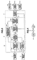
- Fig. 3 shows the functional block diagram of the controller 5 in the second embodiment.
- the preceding vehicle follow-up run controller 50 includes a pre-compensation vehicular velocity command value calculating section 505 connected to the input end of the target inter-vehicle distance calculating section 503 and a corrected vehicular velocity command value calculating section 506 in addition to the inter-vehicle distance command value calculating section 501, the coefficients determining section 502, the target inter-vehicle distance calculating section 503, and the vehicular velocity command value calculating section 504.
- the pre-compensation vehicular velocity command value calculating section 505 calculates the compensated vehicular velocity command value Vc from the command value L * of the inter-vehicle distance through a filter expressed in an equation (9) of TABLE 3.
- the filter in the equation (9) is represented by a product between an inverse of the transfer function from the vehicular velocity command value V* to the actual inter-vehicle distance L and the control response characteristic of the target inter-vehicle distance shown in the equation (7).
- the transfer function from the vehicular velocity command value V* to the actual inter-vehicle distance L is represented by a product between the transfer function of the vehicular velocity control system having the input of the vehicular velocity command value V* and the output of the actual vehicular velocity V (the equation (1)) and a deviation between the actual vehicular velocity V and the vehicular velocity V T of the preceding vehicle, i.e., an integrator to integrate the relative velocity ⁇ V to derive the actual inter-vehicle distance L, as shown in Fig.
- the vehicular velocity control section 4 controls at least one or each of the throttle valve actuator 30, the automatic brake actuator 60, and the A/T gear ratio actuator 40 to make the actual vehicular velocity V equal to the vehicular velocity command value V*'.
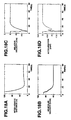
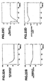
- Figs. 5A through 10C show the results of simulations.
- Figs. 5A, 5B, and 5C show timing charts indicating the inter-vehicle distance, the relative velocity, and the acceleration (a signed acceleration, namely, a variation rate of the vehicular velocity) when a comparative example of the automatic vehicular velocity control apparatus in each of the first and second embodiments is operated in a case where the vehicle has recognized the presence of the preceding vehicle and thereafter approached to the preceding vehicle up to the set (target) inter-vehicle distance as shown in Fig. 11.
- Figs. 6A, 6B, and 6C show timing charts indicating the inter-vehicle distance, the relative velocity, and the acceleration when the automatic vehicular velocity control apparatus in the second embodiment is operated in the same case shown in Fig. 11.
- each solid line denotes a case of the vehicular velocity of 100 Km/h, the initial value of the inter-vehicle distance of 100 m, and the vehicular velocity of the preceding vehicle of 75 Km/h, the initial value of the inter-vehicle distance of 100 m, and the vehicular velocity of the preceding vehicle of 90 Km/h.
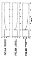
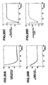
- Figs. 7A, 7B, and 7C show timing charts of the inter-vehicle distance, the relative velocity, and the acceleration of the comparative example as the results of simulations when the other vehicle which has running at a different traffic lane is interrupted into the traffic lane before the vehicle as the new preceding vehicle as shown in Fig. 12.
- Figs. 8A, 8B, and 8C show timing charts of the inter-vehicle distance, the relative velocity, and the acceleration of the automatic vehicular velocity control apparatus in the second embodiment as the results of simulations in the same situation as shown in Fig. 12.
- Figs. 9A, 9B, and 9C show timing charts representing the inter-vehicle distance, the relative velocity, and the acceleration of the case of the comparative example as the results of simulations when the vehicle has made the traffic lane change after the overtake vehicle as the new preceding vehicle to the adjacent overtaking traffic lane to overtake the preceding vehicle (old preceding vehicle) as shown in Fig. 13.
- Figs. 10A, 10B, and 10C show timing charts representing the inter-vehicle distance, the relative velocity, and the acceleration of the automatic vehicular velocity control apparatus in the second embodiment as the results of simulations in the same situation as shown in Fig. 13.
- the vehicular velocity of the vehicle and the vehicular velocity of the preceding vehicle were 75 Km/h
- the vehicular velocity of the new preceding vehicle which is running at the overtake traffic lane was 90 Km/h
- the inter-vehicle distance from the vehicle to the preceding vehicle immediately after the vehicle has entered the overtake traffic lane was 20 m.
- the damping factor and the specific angular frequency as to provide the control response characteristic as to be slowly converged into the command value of the inter-vehicle distance by means of the retrieved previously set map data, the vehicle tended to be approached to the new preceding vehicle but the degree of decrease in the relative velocity became moderate. Then, no large deceleration occurred and the smooth start to follow up the (new) preceding vehicle can be achieved without giving the disagreeable vehicular run to the vehicular occupant(s).
- the damping factor and the specific angular frequency in the inter-vehicle distance control system are previously stored as the maps (TABLE 1 and TABLE 2) in accordance with the inter-vehicle distance deviation and the relative velocity so as to provide the optimum inter-vehicle distance control in various follow-up run situations as shown in Figs. 11 through 13.
- the command value of the vehicular velocity based on the target inter-vehicle distance and the target relative velocity is calculated and the driving force, the braking force, and/or the gear ratio of the transmission 4 is controlled in accordance with the command value of the vehicular velocity.
- the optimum inter-vehicle distance control response can be achieved and the smooth follow-up run to the preceding vehicle can be started without the abrupt deceleration.
- the response characteristic can be improved without sacrifice of the stability in the inter-vehicle distance control system.
- the follow-up run control according to the present invention is applicable to the various follow-up run situations shown in Figs. 11, 12, and 13.
- the damping factor ⁇ M and ⁇ M to determine the response characteristic of the target inter-vehicle distance L T are set in accordance with the inter-vehicle distance deviation (L - L*) and the relative velocity ⁇ V.
- the predetermined constants fv and fL (refer to the equation (8) described above) in the inter-vehicle distance feedback control system are set in accordance with the relative velocity ⁇ V(t) to make the actual inter-vehicle distance L(t) equal to the target inter-vehicle distance L T (t). Then, the response characteristic in the inter-vehicle distance control system can be improved.
- the constants fv and fL in the inter-vehicle distance feedback control system are called gains, the gain fL by which the difference between the target inter-vehicle distance L T (t) and the actual inter-vehicle distance L(t), namely, the target inter-vehicle distance deviation ⁇ L T (t) - L(t) ⁇ is multiplied is called the first gain and the gain fv by which the difference between the target relative velocity ⁇ V(t) and the actual relative velocity ⁇ V(t), namely, the target relative velocity deviation ⁇ ⁇ V T (t) - ⁇ V(t) ⁇ is multiplied is called the second gain.
- the vehicular run disagreeable to the vehicular occupant(s) is given. It is, however in this case, desirable to widen the inter-vehicle distance but to slowly decrease the vehicular velocity. To achieve this, it is necessary to reduce the first gain fL by which the target inter-vehicle distance deviation in the inter-vehicle distance feedback control system ⁇ L T (t) - L(t) ⁇ is multiplied and to increase the second gain fv by which the target relative velocity deviation ⁇ V T (t) - ⁇ V(t) ⁇ is multiplied. Hence, the response characteristic of the inter-vehicle distance feedback control system becomes slow.
- the first gain fL by which the target inter-vehicle deviation ⁇ L T (t) - L(t) ⁇ in the inter-vehicle distance feedback control system is multiplied is increased but the second gain fv by which the target relative velocity deviation ⁇ V T (t) - ⁇ V(t) ⁇ is multiplied is reduced.
- the first and second gains fv and fL in the inter-vehicle distance feedback control system are set in accordance with the relative velocity ⁇ V(t) of the vehicle to the preceding vehicle ⁇ V(t) to achieve the optimum inter-vehicle distance control response to start the smooth follow-up run to the preceding vehicle in spite of the magnitude of the relative velocity ⁇ V(t).
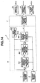
- Fig. 14 shows the functional block diagram of the automatic vehicular velocity control apparatus in the third embodiment according to the present invention.
- the preceding vehicle follow-up run controller 5 functionally includes the inter-vehicle distance command value calculating section 801, the target inter-vehicle distance calculating section 802, the gain determining section 803, and the vehicular velocity command value calculating section 804.
- the preceding vehicle follow-up run controller 8 receives the inter-vehicle distance L and the relative velocity ⁇ V from the inter-vehicle distance sensor 1 and the vehicular velocity V from the vehicular velocity sensor 2.
- the vehicular velocity set as the target vehicle speed is outputted to the vehicular velocity control section 4 as the command value V*(t) of the vehicular velocity.
- the inter-vehicle distance command value calculating section 801 calculates the command value of the inter-vehicle distance in the following equation (11) on the basis of the vehicular velocity V(t) and the relative velocity to the preceding vehicle ⁇ V(t) if the preceding vehicle is recognized by means of the inter-vehicle distance sensor 1.
- the target inter-vehicle distance calculating section 802 derives the target inter-vehicle distance L T (t) and the target relative velocity ⁇ V T (t) in accordance with the filter processing of an equation (13) of TABLE 4.
- ⁇ M and ⁇ M denote the specific angular frequency and the damping factor to determine the response characteristic of the target inter-vehicle distance L T (t) and the target relative velocity ⁇ V T (t). In either case, a designer sets an arbitrary value therefor.
- the equation (14) of TABLE 4 is the transfer function from the command value L*(t) of the inter-vehicle distance to the target inter-vehicle distance L T (t) and is expressed in the second-order equation.
- the gain determining section 803 determines the first gain fL by which the target inter-vehicle distance deviation ⁇ L T (t) - L(t) ⁇ in the inter-vehicle distance feedback control system is multiplied and the second gain fv by which the target relative velocity deviation ⁇ V T (t) - ⁇ V(t) ⁇ is multiplied according to the relative velocity ⁇ V(t).
- the specific angular frequency ⁇ C and the damping coefficient ⁇ C which are previously stored in the maps are derived.
- the specific angular frequency ⁇ C and the damping factor ⁇ C are the parameters to determine the response characteristic of the inter-vehicle distance feedback control system.
- Fig. 14 shows an example of the map representing the specific angular frequency ⁇ C.
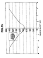
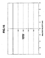
- Fig. 15 shows the example of the damping coefficient.
- the first gain f L and the second gain fv to calculate the command value V*(t) of the vehicular velocity are calculated on the basis of the specific angular velocity ⁇ C and the damping coefficient ⁇ C as shown in equations (15A) and (15B).
- fL ⁇ C 2 / ⁇ nV
- fv 1 - 2 ⁇ c ⁇ c/ ⁇ nV
- ⁇ nV denotes the specific angular frequency in the inter-vehicle distance control system so as to make the detected value of the vehicular velocity (actual vehicular velocity) V(t) equal to the command value V*(t) of the vehicular velocity.
- the first gain fL is proportional to a square ⁇ C of the specific angular frequency in the inter-vehicle distance feedback control system and the second gain fv is proportional to the specific angular frequency ⁇ C.
- the vehicular velocity command value calculating section 804 calculates the command value V*(t) of the vehicular velocity to make the relative velocity ⁇ V(t) equal to the target relative velocity ⁇ V(t) equal to the target relative velocity V T (t) and simultaneously to make the inter-vehicle distance L(t) equal to the target inter-vehicle distance L T (t).
- the first gain fL and the second gain fv determined by the gain determining section 803 according to the relative velocity ⁇ V(t) are used to calculate the command value of the vehicular velocity in accordance with an equation (16).
- V*(t) ⁇ V(t) + ⁇ V(t) ⁇ - ⁇ fv ⁇ V T (t) - ⁇ V(t) ⁇ + f L ⁇ L T (t) - L(t) ⁇
- the vehicular velocity control section 4 is the same as that described in each previous embodiment, namely, adjustably controls at least one or each of the throttle actuator 30, the automatic actuator 60, and/or the A/T gear ratio actuator 60 in order that the actual vehicular velocity V(t) is made equal to the command value V*(t) of the vehicular velocity.
- the first gain fL by which the target inter-vehicle distance deviation ⁇ L T (t) - L(t) ⁇ in the equation (16) is multiplied becomes large and the second gain by which the target relative velocity deviation ⁇ ⁇ V T (t) - ⁇ V(t) ⁇ is multiplied becomes small. Since the specific angular frequency ⁇ c is set to be a larger value as the relative velocity ⁇ V(t) becomes large as shown in Fig. 15, the first gain fL becomes large but the second gain fv becomes small as the relative velocity value ⁇ V(t) becomes large.
- the target inter-vehicle distance deviation ⁇ L T (t) - L(t) ⁇ is fedback to a large degree and the target relative velocity deviation ⁇ L T (t) - ⁇ V(t) ⁇ is fedback to a small degree.
- the command value V*(t) of the vehicular velocity is not largely varied even if the target relative velocity deviation ⁇ V T (t) - ⁇ V(t) ⁇ is large. No abrupt deceleration is carried out even if the relative velocity ⁇ V(t) is large (high).
- the first gain fL by which the target inter-vehicle distance deviation ⁇ L T (t) - L(t) ⁇ in the equation (16) is multiplied becomes reduced but the second gain fv by which the target relative velocity deviation ⁇ V T (t) - ⁇ V(t) ⁇ is multiplied becomes increased.
- the target inter-vehicle distance deviation ⁇ L T (t) - L(t) ⁇ is fedback to a small degree in the calculation of the command value V*(t) in the equation (16) and the target relative velocity deviation ⁇ V T (t) - ⁇ V(t) ⁇ is fedback to a large degree.
- the first gain fL by which the target inter-vehicle distance deviation ⁇ L T (t) - L(t) ⁇ is multiplied is increased to improve the response characteristic in the inter-vehicle distance feedback control system to make the actual inter-vehicle distance L(t) equal to the target inter-vehicle distance L T (t).
- the increase in the first gain fL causes the decrease in the stability in the system.
- the feedforward loop is added to the inter-vehicle distance feedback control system so as to provide the desired target inter-vehicle distance response characteristic from the inter-vehicle distance command value L*(T).
- the compensated command value Vc of the vehicular velocity corrects the command value of the vehicular velocity V*(t) derived by the inter-vehicle distance feedback control system.
- the inter-vehicle distance feedback control system can improve the response characteristic without sacrifice of the stability.
- Fig. 17A shows the functional block diagram of the automatic vehicular velocity control apparatus in the fourth embodiment.
- the preceding vehicle follow-up run controller 800A shown in Fig. 17A includes the pre-compensated vehicular velocity command calculating section 805 and the corrected vehicular velocity command value calculating section 806.
- the pre-compensated vehicular velocity command value calculating section 805 calculates the compensated vehicular velocity command value Vc by carrying out the filtering process of an equation (17) of TABLE 4.
- the filter expressed in the equation (17) of TABLE 4 is represented by the product between the inverse of the transfer function from the vehicular velocity command value V*(t) to the actual inter-vehicle distance L(t) and the responsive characteristic of the target inter-vehicle distance L T (t) shown in the equation (14).
- the transfer function from the command value V*(t) of the vehicular velocity up to the actual inter-vehicle distance L(t) is represented by the product between the transfer function Gv(s) (refer to the equation (1)) in the vehicular velocity control system into which the command value V*(t) of the vehicular velocity is inputted and from which the actual vehicular velocity V(t) is outputted and the difference between the actual vehicular velocity V T (t) of the preceding vehicle, i.e., the integrator to integrate the relative velocity to achieve the actual inter-vehicle distance L(t).
- the initial values to calculate the actual inter-vehicle distance L(t) are the inter-vehicle distance L0 and the relative velocity ⁇ V0 immediately after the vehicle has just been recognized the preceding vehicle.
- the corrected vehicular velocity command value calculating section 806 adds the compensated vehicular velocity command value V*(t) calculated in the inter-vehicle distance feedback control system to derive the corrected command value V*'(t) of the vehicular velocity.
- V*'(t) V T (t) - V*(t) - Vc
- the vehicular velocity control section 4 adjustably controls at least one of the throttle actuator 30, the automatic brake actuator 80, the A/T gear ratio actuator 70 to make the actual vehicular velocity equal to the corrected command value V*'(t).
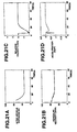
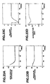
- Figs. 18A through 18D show the results of simulations of the inter-vehicle distance, the vehicular velocity, the relative velocity, and the accelerations in the automatic vehicular velocity control apparatus in either of the first or the second embodiment when the specific angular frequency ⁇ c was lowered.
- Figs. 19A through 19D show those results of simulations thereof in a case where the specific angular frequency is lowered.
- Figs. 20A through 20D show those results of simulations thereof in each of the third and fourth embodiments.
- each solid line denotes the target value and the broken line denotes the actual value.
- the response in the inter-vehicle distance control system is quickened with the specific angular frequency in each of the first and second embodiments increased.
- Figs. 21A through 21D show the results of simulations when the specific angular frequency in the inter-vehicle distance feedback control system in each of the first and second preferred embodiments is increased.
- Figs. 22A through 22D show the results of simulations when the specific angular frequency in the inter-vehicle distance feedback control system in each of the first and second preferred embodiments is lowered.
- Figs. 23A through 23D show the results of simulations when each of the third and fourth embodiments is operated.
- the response in the inter-vehicle distance control system is quickened with the specific angular frequency increased in either of the first or second embodiment.
- the actual inter-vehicle distance L(t) is varied in such a manner as to be made substantially coincident with the target inter-vehicle distance L T (t) as shown in Figs. 21A through 21D but the large deceleration variation occurs after the follow-up run start.
- the actual inter-vehicle distance L(t) is varied in such a manner as to be made substantially coincident with the target inter-vehicle distance L T (t) and moderate variation in the deceleration occurs.
- the actual inter-vehicle distance L(t) is varied in such a manner as to be substantially made coincident with the target inter-vehicle distance L T (t) and the variation in the deceleration becomes moderate.
- the actual inter-vehicle distance L(t) is varied in such a manner as to be substantially made coincident with the target inter-vehicle distance L T (t) and no large variation in the deceleration occurs after the start of the follow-up run.
- the optimum inter-vehicle control response characteristic can be achieved in various preceding vehicle follow-up run situations. No large variation occurs after the start of the preceding vehicle follow-up run.
- the response characteristic an be increased without sacrifice of the stability in the inter-vehicle distance feedback control system.
- the first gain fL by which the target inter-vehicle distance feedback control system is multiplied and the second gain fv by which the target relative velocity deviation ⁇ V T (t) - ⁇ V(t) ⁇ in the above-described control system is multiplied are set in accordance with the relative velocity ⁇ V(t).
- Fig. 17B shows an alternative of the fourth preferred embodiment of the automatic vehicular velocity control apparatus according to the present invention.
- the coefficients determining section 502 corresponds to the maps shown in TABLE 1 and TABLE 2 and shown in Fig. 3 and the target inter-vehicle distance calculating section 810 having the transfer function expressed as ⁇ M 2 /(s 2 + 2 ⁇ M ⁇ s + ⁇ M 2 ) derives the target inter-vehicle distance L* (or L T ) and the target relative velocity ⁇ V* (or ⁇ V T ).
- the vehicular velocity command value calculating section 820 includes: a first subtractor D L to subtract the target inter-vehicle distance L* from the actual inter-vehicle distance L to derive the target inter-vehicle distance deviation (L* - L, namely, ⁇ L T (t) - L(t) ⁇ ); a second subtractor Dv to subtract the target relative velocity ⁇ V* from the actual relative velocity ⁇ V to derive the target relative velocity deviation ( ⁇ V* - ⁇ V, namely, ⁇ V T (t) - ⁇ V(t) ⁇ ); a first multiplier having the first gain fL by which the subtraction result is multiplied to derive fL x (L* - L); a second multiplier having the second gain fv by which the subtraction result is multiplied to derive fv x ( ⁇ V* - ⁇ V); a summer S1 to add the vehicular velocity V to the relative velocity ⁇ V and subtract fL x (L* - L
- the pre-compensated vehicular velocity command value calculating section 850 has the transfer function as given by ⁇ M 2 s(s + ⁇ v)/ ⁇ v(s 2 + 2 ⁇ M ⁇ M s + ⁇ M 2 ).
- the individual numerical values of the specific angular frequency ⁇ M and the damping factor ⁇ M are derived from the maps 502 according to the relative velocity ⁇ V and the inter-vehicle distance deviation ⁇ L.
- Each of the numerical values of ⁇ M and ⁇ M is previously distributed into the maps in accordance with the signed values of the inter-vehicle distance deviation ⁇ L and of the relative velocity ⁇ V of the vehicle to the preceding vehicle.
- an inter-vehicle distance (feedback) control system defined in the appended claims includes the inter-vehicle distance sensor 1; the vehicular velocity sensor 2; the inter-vehicle distance command calculating section 501 (801); the coefficients determining section 502; the target inter-vehicle distance calculating section 503 (802); and the vehicular velocity command value calculating section 504 (803, 804) in each of the first, second, third, and fourth embodiments and includes the sections 810 and 820 shown in Fig. 17B and the vehicular velocity control system includes the vehicular velocity control section 4 and the vehicular velocity sensor 2 in each embodiment.
Landscapes
- Engineering & Computer Science (AREA)
- Transportation (AREA)
- Mechanical Engineering (AREA)
- Automation & Control Theory (AREA)
- Chemical & Material Sciences (AREA)
- Combustion & Propulsion (AREA)
- Remote Sensing (AREA)
- Radar, Positioning & Navigation (AREA)
- Aviation & Aerospace Engineering (AREA)
- Physics & Mathematics (AREA)
- General Physics & Mathematics (AREA)
- Control Of Driving Devices And Active Controlling Of Vehicle (AREA)
- Controls For Constant Speed Travelling (AREA)
- Control Of Vehicle Engines Or Engines For Specific Uses (AREA)
- Traffic Control Systems (AREA)
- Regulating Braking Force (AREA)
- Control Of Transmission Device (AREA)
Claims (18)
- Appareil de régulation automatique de vitesse d'un véhicule destiné à un véhicule automobile, comprenant :caractérisé en ce que l'appareil de régulation automatique de vitesse d'un véhicule comprend en outre :un détecteur (1) de distance inter-véhicule destiné à détecter une distance (L) inter-véhicule depuis le véhicule jusqu'à un véhicule précédent roulant devant le véhicule ;un détecteur de vitesse d'un véhicule (2) destiné à détecter une vitesse (V) de véhicule ;un détecteur de vitesse (1) relative destiné à détecter une vitesse relative (ΔV) du véhicule précédent jusqu'au véhicule ;un calculateur (501, 801) de valeur de commande de distance inter-véhicule destiné à calculer une valeur de commande (L*) de la distance inter-véhicule ; etune section de régulation (4) de vitesse de véhicule destiné à réguler au moins une parmi une poussée (3) du véhicule, une force de freinage (6) du véhicule, et un rapport de transmission d'une transmission de véhicule de telle manière qu'une valeur détectée (V) de la vitesse de véhicule est rapprochée pour égaler une valeur de commande (V*) de la vitesse du véhicule,une section (502, 503, 802, 803) de détermination de caractéristique de réponse de régulation cible d'une distance inter-véhicule destiné à déterminer une caractéristique de réponse de régulation d'un système de régulation de distance inter-véhicule en réponse à un écart (ΔL) entre la valeur de commande (L*) de la distance inter-véhicule et une valeur de (L) détectée de ce dernier et une valeur (ΔV) détectée de la vitesse relative ; etun calculateur (504, 804) de valeur de commande de vitesse de véhicule destiné à calculer la valeur de commande (V*) de la vitesse de véhicule sur base de la caractéristique de réponse de régulation déterminée du système de régulation de distance inter-véhicule.
- Appareil de régulation automatique de vitesse d'un véhicule destiné à un véhicule automobile selon la revendication 1, dans lequel la section de détermination de caractéristique de réponse de régulation cible d'une distance inter-véhicule inclut une mémoire (502) dans laquelle une pluralité de modes de régulation et de caractéristiques de réponses de régulation correspondant aux modes de régulation respectifs sont mémorisés au préalable sur la base de signes et d'amplitudes de l'écart et de la valeur (ΔV) détectée de la vitesse relative.
- Appareil de régulation automatique de vitesse d'un véhicule destiné à un véhicule automobile selon la revendication 2, dans lequel la mémoire inclut des tableaux bidimensionnels (TABLEAU 1, TABLEAU 2), chaque tableau bidimensionnel ayant un axe longitudinal de l'écart (ΔL) et un axe latéral de la valeur (ΔV) détectée de la vitesse relative dont chacun possède un coefficient destiné à déterminer la caractéristique de réponse de régulation mémorisée au préalable.
- Appareil de régulation automatique de vitesse d'un véhicule destiné à un véhicule automobile selon la revendication 3, dans lequel chaque coefficient destiné à déterminer la caractéristique de réponse de régulation est une fréquence angulaire (ωM) spécifique et un facteur d'amortissement (ζM) du système de régulation de distance inter-véhicule.
- Appareil de régulation automatique de vitesse d'un véhicule destiné à un véhicule automobile selon la revendication 4, dans lequel le système de régulation de distance inter-véhicule inclut un calculateur de valeur cible (503) destiné à calculer une valeur cible (LT) de la distance inter-véhicule et une valeur cible (ΔVT) de la vitesse relative grâce à la valeur de commande de distance inter-véhicule en utilisant un premier filtre prescrit par la fréquence angulaire (ωM) spécifique et le facteur d'amortissement (ζM) choisi dans la mémoire et le calculateur de valeur de commande de vitesse de véhicule calcule la vitesse (V*) de commande de vitesse de véhicule sur base des valeurs détectées de la distance inter-véhicule, la vitesse (ΔV) relative, et la vitesse (V) de véhicule et les valeurs cibles de la distance inter-véhicule et la vitesse relative.
- Appareil de régulation automatique de vitesse d'un véhicule destiné à un véhicule automobile selon la revendication 5, dans lequel le premier filtre est un filtre de second ordre.
- Appareil de régulation automatique de vitesse d'un véhicule destiné à un véhicule automobile selon la revendication 6, dans lequel une fonction de transfert du filtre de second ordre est exprimée par ωM 2/(s2 + 2ζM s + ωM 2), dans laquelle s représente un opérateur de transformation de Laplace.
- Appareil de régulation automatique de vitesse d'un véhicule destiné à un véhicule automobile selon la revendication 7, comprenant en outre : un calculateur de valeur de correction pour calculer une valeur de correction pour la valeur (V*) de commande de vitesse de véhicule calculée par le calculateur de valeur de commande de vitesse de véhicule en utilisant un second filtre ayant une fonction de transfert prescrite par la fonction de transfert du premier filtre, une inverse d'une fonction de transfert du système de régulation de vitesse du véhicule, et un élément d'intégration ; et une section de correction de valeur de commande de vitesse de véhicule destiné à corriger la valeur (V*) de commande de vitesse de véhicule en utilisant la valeur de correction calculée par le calculateur de valeur de correction.
- Appareil de régulation automatique de vitesse d'un véhicule destiné à un véhicule automobile selon la revendication 8, dans lequel la fonction de transfert du second filtre est exprimée par ωM 2s(s + ωv)/ωv (s2 + 2ζMωMs + ωM 2), dans laquelle ωv représente une fréquence angulaire de point de freinage dans un système de régulation de vitesse de véhicule constitué par la section de régulation de vitesse de véhicule.
- Appareil de régulation automatique de vitesse d'un véhicule destiné à un véhicule automobile selon la revendication 9, dans lequel le calculateur de valeur de correction est un système d'action anticipatrice relié entre le déterminateur de caractéristique de réponse de régulation et le calculateur de valeur de commande de vitesse de véhicule.
- Appareil de régulation automatique de vitesse d'un véhicule destiné à un véhicule automobile selon la revendication 1, dans lequel le détecteur de vitesse relative comprend un différenciateur destiné à différencier la valeur détectée de la distance inter-véhicule.
- Appareil de régulation automatique de vitesse d'un véhicule destiné à un véhicule automobile, comprenant :caractérisé en ce que l'appareil de régulation automatique de vitesse de véhicule comprend en outreun détecteur (1) de distance inter-véhicule destiné à détecter une distance (L) inter-véhicule depuis le véhicule jusqu'à un véhicule précédent roulant devant le véhicule ;un détecteur (2) de vitesse de véhicule destiné à détecter une vitesse (V) de véhicule du véhicule ;un détecteur (1) de vitesse relative destiné à détecter une vitesse relative (ΔV) du véhicule précédent du véhicule ;une section de calcul de valeur de commande de distance inter-véhicule (501) destinée à calculer une valeur de commande (L*) d'une distance inter-véhicule ; etune section de régulation (4) de vitesse de véhicule destinée à réguler au moins une parmi une poussée du véhicule au travers d'un papillon des gaz (3), une force de freinage d'un système de freinage (6) d'un véhicule, et un rapport de transmission d'une transmission de véhicule de telle manière que la valeur V détectée de la vitesse de véhicule est approchée de manière à égaler une valeur (V*) de commande de cette dernière,une section de calcul (504) de valeur de commande de vitesse de véhicule destinée à calculer la valeur (V*) de commande de la vitesse de véhicule destiné à rapprocher la valeur (L) détectée de la distance inter-véhicule pour la rendre égale à la valeur (LT) cible de la distance inter-véhicule sur la base de la valeur (V) détectée de la vitesse de véhicule, la valeur (ΔV) détectée de la vitesse relative, et l'écart entre la valeur (LT) cible de la distance inter-véhicule et la valeur (L) détectée de cette dernière.une section de calcul (503) de distance cible inter-véhicule destinée à déterminer une valeur cible (LT) de la di inter-véhicule prescrivant une variation de la distance inter-véhicule dans le temps jusqu'à ce que la valeur (L) détectée de la distance inter-véhicule ait atteint la valeur de commande (LT) de la distance inter-véhicule ;une section de détermination de gain (820) destinée à déterminer un premier gain (fL), par laquelle un écart entre la valeur cible (LT) de la distance inter-véhicule et la valeur (L) détectée de la distance inter-véhicule est multipliée selon la valeur détectée (ΔV) de la vitesse relative ; et
- Appareil de régulation automatique de vitesse d'un véhicule destiné à un véhicule automobile selon la revendication 12, dans lequel la section de détermination de valeur cible détermine en outre une valeur cible (ΔVT) de la vitesse relative prescrivant la variation de la vitesse relative (ΔV) dans le temps jusqu'à ce que la valeur (L) détectée de la distance inter-véhicule ait atteint la valeur de commande (L*) de la distance inter-véhicule, la section de détermination de gain (803) détermine en outre un second gain (fv) par lequel un autre écart entre la valeur cible de la vitesse relative et la valeur détectée de cette dernière est multiplié selon la valeur (ΔV) détectée de la vitesse relative, et la section de calcul de valeur de commande de vitesse de véhicule calcule la valeur (V*) de commande de la vitesse de véhicule destiné à rapprocher la valeur (V) détectée de la vitesse de véhicule pour l'égaliser à la valeur cible de cette dernière sur base de l'écart multiplié par le premier gain et l'autre écart multiplié par le second gain (fv).
- Appareil de régulation automatique de vitesse d'un véhicule destiné à un véhicule automobile selon la revendication 13, comprenant en outre une section de calcul (505) de valeur de correction ou pour calculer une valeur (Vc) de correction de la vitesse de véhicule à partir de la valeur de commande de distance inter-véhicule déterminée par la section de détermination de valeur cible en utilisant un filtre ayant une fonction de transfert incluant une caractéristique de transfert de la valeur (L*) de commande de la distance inter-véhicule déterminée par la section de détermination de valeur cible (LT) jusqu'à la valeur cible de la distance inter-véhicule et une caractéristique de transfert inverse de la caractéristique de transfert du système de régulation de vitesse de véhicule à laquelle un élément d'intégration est ajouté et une section de correction de valeur de commande de vitesse de véhicule destiné à corriger la valeur de commande de la vitesse de véhicule selon la valeur corrigée de la vitesse de véhicule.
- Appareil de régulation automatique de vitesse d'un véhicule destiné à un véhicule automobile selon la revendication 14, dans lequel la section de détermination de gain accroít le premier gain (fL) lorsque la valeur détectée de la vitesse relative augmente.
- Appareil de régulation automatique de vitesse d'un véhicule destiné à un véhicule automobile selon la revendication 13, dans lequel la section de détermination de gain détermine le premier gain (fL) et le second gain (fv) comme suit : fL = ωc2/ωnv ; fv = 1 - 2ζcωc/ωnv , où ωc représente une fréquence angulaire spécifique, ζc représente un facteur d'amortissement, la fréquence angulaire spécifique et le facteur d'amortissement étant tous deux des paramètres destinés à déterminer une caractéristique de réponse d'un système de régulation de rétroaction de distance inter-véhicule et étant mémorisés dans une mémoire de l'appareil de régulation automatique de vitesse d'un véhicule sous la forme de mappes respectives selon la valeur détectée de la vitesse relative et ωnv représente une fréquence angulaire spécifique du système de contrôle de vitesse de véhicule afin d'approcher la valeur détectée de la vitesse de véhicule de manière à la rendre égale à la valeur de commande de cette dernière.
- Appareil de régulation automatique de vitesse d'un véhicule destiné à un véhicule automobile selon la revendication 16, dans lequel la section de calcul de valeur de commande de vitesse de véhicule calcule la valeur de commande V*(t) de la vitesse de véhicule comme suit : V*(t) = {V(t) + ΔV(t)} - [fv x {ΔVT(t) ΔV(t)} + fL x{LT(t) - L(t)}], dans laquelle V(t) représente la valeur détectée de la vitesse de véhicule, ΔV(t) représente la valeur détectée de la vitesse relative, fv représente le second gain, ΔVT(t) représente la valeur cible de la vitesse relative et ΔV(t) représente la valeur détectée de la vitesse relative, fL représente le premier gain, LT(t) représente la valeur cible de la distance inter-véhicule, et L(t) représente la valeur détectée de la distance inter-véhicule.
- Appareil de régulation automatique de vitesse d'un véhicule destiné à un véhicule automobile selon la revendication 17, dans lequel la fréquence angulaire ωc spécifique dans le système de contrôle de rétroaction de distance inter-véhicule est mémorisée dans l'une des mappes correspondantes de telle manière que la valeur de la fréquence angulaire ωc spécifique est augmentée en proportion de l'augmentation d'une grandeur de la valeur détectée de la vitesse relative.
Applications Claiming Priority (4)
| Application Number | Priority Date | Filing Date | Title |
|---|---|---|---|
| JP24018098 | 1998-08-26 | ||
| JP24018098 | 1998-08-26 | ||
| JP16682899 | 1999-06-14 | ||
| JP16682899A JP3661495B2 (ja) | 1998-08-26 | 1999-06-14 | 先行車追従制御装置 |
Publications (3)
| Publication Number | Publication Date |
|---|---|
| EP0982172A2 EP0982172A2 (fr) | 2000-03-01 |
| EP0982172A3 EP0982172A3 (fr) | 2000-06-21 |
| EP0982172B1 true EP0982172B1 (fr) | 2005-05-11 |
Family
ID=26491074
Family Applications (1)
| Application Number | Title | Priority Date | Filing Date |
|---|---|---|---|
| EP99116561A Expired - Lifetime EP0982172B1 (fr) | 1998-08-26 | 1999-08-24 | Régulateur de vitesse automatique avec régulation de la distance entre deux véhicules |
Country Status (4)
| Country | Link |
|---|---|
| US (2) | US6330507B1 (fr) |
| EP (1) | EP0982172B1 (fr) |
| JP (1) | JP3661495B2 (fr) |
| DE (1) | DE69925211T2 (fr) |
Cited By (1)
| Publication number | Priority date | Publication date | Assignee | Title |
|---|---|---|---|---|
| WO2017084601A1 (fr) * | 2015-11-19 | 2017-05-26 | 深圳前海达闼云端智能科技有限公司 | Procédé, dispositif et système de commande pour des véhicules dans l'internet des véhicules et véhicule |
Families Citing this family (58)
| Publication number | Priority date | Publication date | Assignee | Title |
|---|---|---|---|---|
| JP3661495B2 (ja) * | 1998-08-26 | 2005-06-15 | 日産自動車株式会社 | 先行車追従制御装置 |
| US6233515B1 (en) | 1998-12-07 | 2001-05-15 | Jaguar Car, Limited | Adaptive vehicle cruise control system and methodology |
| JP3690185B2 (ja) * | 1999-05-25 | 2005-08-31 | 日産自動車株式会社 | 先行車追従制御装置 |
| JP3661496B2 (ja) * | 1999-06-15 | 2005-06-15 | 日産自動車株式会社 | 先行車追従制御装置 |
| DE10015301A1 (de) | 2000-03-28 | 2001-10-04 | Bosch Gmbh Robert | Verfahren zur Unterbrechnung einer Geschwindigkeits- oder Abstandsregelung eines Regelsystems eines Kraftfahrzeugs |
| US6529814B2 (en) | 2000-05-16 | 2003-03-04 | Nissan Motor Co., Ltd. | System and method for controlling vehicle velocity and inter-vehicle distance |
| CN1263624C (zh) | 2000-05-16 | 2006-07-12 | 日产自动车株式会社 | 用于控制车辆速度和车辆间距离的系统和方法 |
| JP4254936B2 (ja) | 2000-06-27 | 2009-04-15 | 日産自動車株式会社 | 車両の警報発生装置 |
| JP3817412B2 (ja) * | 2000-08-02 | 2006-09-06 | ジヤトコ株式会社 | 無段変速機の変速制御装置 |
| WO2002014898A2 (fr) | 2000-08-16 | 2002-02-21 | Raytheon Company | Systeme de detection d'objets proches |
| US6577269B2 (en) | 2000-08-16 | 2003-06-10 | Raytheon Company | Radar detection method and apparatus |
| US6642908B2 (en) | 2000-08-16 | 2003-11-04 | Raytheon Company | Switched beam antenna architecture |
| EP1870730A3 (fr) | 2000-08-16 | 2011-07-20 | Valeo Radar Systems, Inc. | Systèmes et techniques de radar automobile |
| US6903679B2 (en) | 2000-08-16 | 2005-06-07 | Raytheon Company | Video amplifier for a radar receiver |
| AU2001291299A1 (en) | 2000-09-08 | 2002-03-22 | Raytheon Company | Path prediction system and method |
| JP3649108B2 (ja) * | 2000-09-14 | 2005-05-18 | 日産自動車株式会社 | 車両用追従走行制御装置 |
| JP3797115B2 (ja) * | 2001-02-15 | 2006-07-12 | 日産自動車株式会社 | 車速制御装置 |
| US6708100B2 (en) | 2001-03-14 | 2004-03-16 | Raytheon Company | Safe distance algorithm for adaptive cruise control |
| US6737963B2 (en) * | 2001-03-30 | 2004-05-18 | Koninklijke Philips Electronics N.V. | Driver tailgating and following aid |
| JP3788266B2 (ja) * | 2001-05-11 | 2006-06-21 | 日産自動車株式会社 | 車両用走行制御装置 |
| US20030022681A1 (en) * | 2001-07-24 | 2003-01-30 | Ruppel Christopher D. | Adaptive dynamic technique for multi-path signal processing |
| JP2003039980A (ja) * | 2001-07-31 | 2003-02-13 | Nissan Motor Co Ltd | 車両用走行制御装置 |
| WO2003012470A2 (fr) * | 2001-08-02 | 2003-02-13 | Siemens Aktiengesellschaft | Systemes de manutention pourvus de dispositifs de localisation radio haute frequence |
| US6970142B1 (en) | 2001-08-16 | 2005-11-29 | Raytheon Company | Antenna configurations for reduced radar complexity |
| US7183995B2 (en) | 2001-08-16 | 2007-02-27 | Raytheon Company | Antenna configurations for reduced radar complexity |
| US6995730B2 (en) | 2001-08-16 | 2006-02-07 | Raytheon Company | Antenna configurations for reduced radar complexity |
| US6535808B1 (en) * | 2001-12-19 | 2003-03-18 | Delphi Technologies, Inc. | Deceleration control for automatic automotive speed control apparatus |
| US6611227B1 (en) | 2002-08-08 | 2003-08-26 | Raytheon Company | Automotive side object detection sensor blockage detection system and related techniques |
| US6870468B2 (en) * | 2002-09-27 | 2005-03-22 | Nissan Motor Co., Ltd. | Adaptive cruise speed controlling apparatus and method for automotive vehicle |
| US7272482B2 (en) * | 2002-09-30 | 2007-09-18 | Nissan Motor Co., Ltd. | Preceding-vehicle following control system |
| US6778897B2 (en) * | 2002-11-27 | 2004-08-17 | Visteon Global Technologies, Inc. | Adaptive cruise control system and strategy |
| SE525479C2 (sv) * | 2003-07-10 | 2005-03-01 | Volvo Lastvagnar Ab | Metod för optimering av bromsförlopp i fordon |
| JP4379199B2 (ja) | 2004-05-17 | 2009-12-09 | 日産自動車株式会社 | 車線変更支援装置および方法 |
| JP2005339241A (ja) | 2004-05-27 | 2005-12-08 | Nissan Motor Co Ltd | モデル予測制御装置および車両用推奨操作量生成装置 |
| JP4400418B2 (ja) | 2004-10-29 | 2010-01-20 | 日産自動車株式会社 | 車間距離制御装置及び車間距離制御方法並びに運転操作支援装置及び運転操作支援方法 |
| JP4451315B2 (ja) * | 2005-01-06 | 2010-04-14 | 富士重工業株式会社 | 車両の運転支援装置 |
| FR2880591B1 (fr) * | 2005-01-11 | 2008-08-22 | Renault Sas | Systeme de controle longitudinal d'une voiture |
| US20060289216A1 (en) * | 2005-06-16 | 2006-12-28 | Ryoji Kato | Relative speed computing apparatus and inter-vehicle distance control apparatus |
| JP5653901B2 (ja) | 2008-03-31 | 2015-01-14 | ヴァレオ・レイダー・システムズ・インコーポレーテッド | 自動車レーダ・センサ閉塞検出装置 |
| JP5088444B2 (ja) * | 2009-03-04 | 2012-12-05 | トヨタ自動車株式会社 | 追従走行制御装置 |
| US8577579B2 (en) * | 2010-02-01 | 2013-11-05 | Bendix Commercial Vehicle Systems Llc | Engine control request from adaptive control with braking controller |
| JP5126336B2 (ja) * | 2010-05-13 | 2013-01-23 | 株式会社デンソー | 車両用速度制御装置 |
| US9403532B2 (en) * | 2010-07-09 | 2016-08-02 | Allison Transmission, Inc. | Closed-loop transmission integration with forward and/or reverse assist system |
| JP5494332B2 (ja) * | 2010-07-27 | 2014-05-14 | トヨタ自動車株式会社 | 車両制御システム |
| US8907774B2 (en) | 2011-03-01 | 2014-12-09 | Bendix Commercial Vehicle Systems Llc | System and method for monitoring tire condition |
| US8643505B2 (en) | 2011-06-01 | 2014-02-04 | Nissan North America, Inc. | Host vehicle with externally perceivable cruise control indicating device |
| CN103287427A (zh) * | 2013-06-05 | 2013-09-11 | 苏州惠瑞自动化集成有限公司 | 自动化车速控制系统 |
| DE102017203739A1 (de) | 2017-03-07 | 2018-09-13 | Continental Teves Ag & Co. Ohg | Automatisches Notbremssystem |
| US10752246B2 (en) | 2017-07-01 | 2020-08-25 | Tusimple, Inc. | System and method for adaptive cruise control with proximate vehicle detection |
| US10737695B2 (en) | 2017-07-01 | 2020-08-11 | Tusimple, Inc. | System and method for adaptive cruise control for low speed following |
| US10493988B2 (en) * | 2017-07-01 | 2019-12-03 | TuSimple | System and method for adaptive cruise control for defensive driving |
| CN109753056B (zh) * | 2017-11-07 | 2022-12-20 | 北京图森未来科技有限公司 | 一种车辆自动巡航的速度动态控制方法和装置 |
| CN109878518B (zh) * | 2017-12-04 | 2021-08-17 | 京东方科技集团股份有限公司 | 用于控制车辆行驶的装置及方法 |
| JP6541848B1 (ja) * | 2018-06-21 | 2019-07-10 | 三菱電機株式会社 | 車間距離制御装置 |
| CN113439048A (zh) * | 2019-02-14 | 2021-09-24 | 三菱电机株式会社 | 车间距离控制装置 |
| CN114655203A (zh) * | 2020-12-23 | 2022-06-24 | 大众问问(北京)信息科技有限公司 | 一种辅助驾驶方法、装置、设备及存储介质 |
| CN113200038B (zh) * | 2021-06-17 | 2022-11-01 | 清华大学 | 一种适用于电动车的增量式速度控制方法 |
| US12472911B2 (en) * | 2023-07-11 | 2025-11-18 | Deere & Company | Systems and methods for ground distance control |
Family Cites Families (23)
| Publication number | Priority date | Publication date | Assignee | Title |
|---|---|---|---|---|
| US3820622A (en) * | 1973-07-30 | 1974-06-28 | Bendix Corp | Model referenced speed control for automobiles |
| JPS61146644A (ja) * | 1984-12-19 | 1986-07-04 | Nissan Motor Co Ltd | 車両走行制御装置 |
| JP2646146B2 (ja) * | 1990-03-28 | 1997-08-25 | 三菱電機株式会社 | 車間距離制御装置 |
| DE4209060C2 (de) * | 1992-03-20 | 1994-12-15 | Daimler Benz Ag | Verfahren zur Regelung des Abstandes zwischen fahrenden Kraftfahrzeugen |
| JPH06227280A (ja) * | 1993-02-02 | 1994-08-16 | Mitsubishi Electric Corp | 車間距離制御装置 |
| GB9303434D0 (en) * | 1993-02-20 | 1993-04-07 | Lucas Ind Plc | Method of and apparatus for cruise control |
| JP3569926B2 (ja) * | 1993-03-03 | 2004-09-29 | 株式会社デンソー | 車両走行制御装置 |
| US5493302A (en) * | 1993-10-01 | 1996-02-20 | Woll; Jerry | Autonomous cruise control |
| US5839534A (en) * | 1995-03-01 | 1998-11-24 | Eaton Vorad Technologies, Llc | System and method for intelligent cruise control using standard engine control modes |
| DE19624615C2 (de) * | 1996-06-20 | 2001-09-20 | Volkswagen Ag | Verfahren zur Abstandsregelung für ein Kraftfahrzeug |
| DE19654769A1 (de) * | 1996-12-30 | 1998-07-02 | Teves Gmbh Alfred | Verfahren und Vorrichtung zur Fahrzeugsteuerung bzw. -regelung |
| JPH10240180A (ja) | 1997-02-21 | 1998-09-11 | Kouji Suitsu | 張紙固定具 |
| JP3677959B2 (ja) | 1997-08-27 | 2005-08-03 | 日産自動車株式会社 | 先行車追従制御装置 |
| US5959572A (en) * | 1997-03-31 | 1999-09-28 | Nissan Motor Co., Ltd. | Vehicle follow-up control apparatus |
| JP3736017B2 (ja) | 1997-03-31 | 2006-01-18 | 日産自動車株式会社 | 先行車追従制御装置 |
| FR2770016B1 (fr) * | 1997-10-17 | 1999-12-10 | Renault | Procede de regulation de la distance entre deux vehicules mobiles |
| JP3518286B2 (ja) | 1997-10-23 | 2004-04-12 | 日産自動車株式会社 | 先行車追従制御装置 |
| DE19750338A1 (de) * | 1997-11-13 | 1999-05-20 | Siemens Ag | Fahrtregelungssystem für Fahrzeuge, insbesondere für Kraftfahrzeuge |
| JPH11166828A (ja) | 1997-12-05 | 1999-06-22 | Takao Sugimoto | 連段型層別沈下素子 |
| JP3402173B2 (ja) * | 1998-01-08 | 2003-04-28 | 日産自動車株式会社 | 自動速度制御装置 |
| JP3395623B2 (ja) * | 1998-01-19 | 2003-04-14 | 株式会社日立製作所 | 車両の走行制御装置 |
| JP3690126B2 (ja) * | 1998-07-23 | 2005-08-31 | 日産自動車株式会社 | 車両用追従走行制御装置 |
| JP3661495B2 (ja) * | 1998-08-26 | 2005-06-15 | 日産自動車株式会社 | 先行車追従制御装置 |
-
1999
- 1999-06-14 JP JP16682899A patent/JP3661495B2/ja not_active Expired - Fee Related
- 1999-08-24 EP EP99116561A patent/EP0982172B1/fr not_active Expired - Lifetime
- 1999-08-24 DE DE69925211T patent/DE69925211T2/de not_active Expired - Lifetime
- 1999-08-26 US US09/384,292 patent/US6330507B1/en not_active Expired - Lifetime
-
2001
- 2001-11-16 US US09/987,891 patent/US6473686B2/en not_active Expired - Lifetime
Cited By (1)
| Publication number | Priority date | Publication date | Assignee | Title |
|---|---|---|---|---|
| WO2017084601A1 (fr) * | 2015-11-19 | 2017-05-26 | 深圳前海达闼云端智能科技有限公司 | Procédé, dispositif et système de commande pour des véhicules dans l'internet des véhicules et véhicule |
Also Published As
| Publication number | Publication date |
|---|---|
| EP0982172A3 (fr) | 2000-06-21 |
| DE69925211D1 (de) | 2005-06-16 |
| JP3661495B2 (ja) | 2005-06-15 |
| US6330507B1 (en) | 2001-12-11 |
| US20020055813A1 (en) | 2002-05-09 |
| EP0982172A2 (fr) | 2000-03-01 |
| DE69925211T2 (de) | 2005-10-06 |
| US6473686B2 (en) | 2002-10-29 |
| JP2000135934A (ja) | 2000-05-16 |
Similar Documents
| Publication | Publication Date | Title |
|---|---|---|
| EP0982172B1 (fr) | Régulateur de vitesse automatique avec régulation de la distance entre deux véhicules | |
| US7561955B2 (en) | Preceding-vehicle following control system | |
| US6597981B2 (en) | Apparatus and method for controlling vehicular velocity of host vehicle to follow preceding vehicle running ahead of host vehicle | |
| US6188950B1 (en) | System and method for controlling inter-vehicle distance to preceding vehicle for automotive vehicle equipped with the system and method | |
| US6470257B1 (en) | Adaptive cruise control system for automotive vehicles | |
| US8265850B2 (en) | Method and apparatus for target vehicle following control for adaptive cruise control | |
| US7162349B2 (en) | Driving assist system and method with accelerator pedal reaction force control | |
| US6985805B2 (en) | Adaptive cruise control system | |
| US5959572A (en) | Vehicle follow-up control apparatus | |
| US6175799B1 (en) | Apparatus and method for automatically controlling vehicular velocity | |
| EP1225079B1 (fr) | Régulateur de vitesse adaptif avec régulation de la distance entre deux véhicules | |
| EP1055542B1 (fr) | Régulateur de vitesse avec régulation de la distance entre deux véhicules et variation de gain | |
| US7054733B2 (en) | Adaptive cruise control system for vehicle | |
| US20020173896A1 (en) | System and method for controlling vehicle velocity and inter-vehicle distance | |
| EP1061495B1 (fr) | Procédure et appareil pour la régulation de la vitesse de croisière et la distance entre deux véhicules | |
| JP4243155B2 (ja) | 車両速度の制限方法および装置 | |
| US6870468B2 (en) | Adaptive cruise speed controlling apparatus and method for automotive vehicle | |
| JP4161822B2 (ja) | 追従走行制御装置 | |
| JPH1120503A (ja) | 先行車追従制御装置 | |
| JPH0421240B2 (fr) | ||
| JP3835389B2 (ja) | 先行車追従制御装置 | |
| JP3630124B2 (ja) | 先行車両追従制御装置 | |
| JP2004009831A (ja) | 車間距離制御装置 |
Legal Events
| Date | Code | Title | Description |
|---|---|---|---|
| PUAI | Public reference made under article 153(3) epc to a published international application that has entered the european phase |
Free format text: ORIGINAL CODE: 0009012 |
|
| 17P | Request for examination filed |
Effective date: 19990824 |
|
| AK | Designated contracting states |
Kind code of ref document: A2 Designated state(s): DE FR GB |
|
| AX | Request for extension of the european patent |
Free format text: AL;LT;LV;MK;RO;SI |
|
| PUAL | Search report despatched |
Free format text: ORIGINAL CODE: 0009013 |
|
| AK | Designated contracting states |
Kind code of ref document: A3 Designated state(s): AT BE CH CY DE DK ES FI FR GB GR IE IT LI LU MC NL PT SE |
|
| AX | Request for extension of the european patent |
Free format text: AL;LT;LV;MK;RO;SI |
|
| AKX | Designation fees paid |
Free format text: DE FR GB |
|
| 17Q | First examination report despatched |
Effective date: 20010719 |
|
| GRAP | Despatch of communication of intention to grant a patent |
Free format text: ORIGINAL CODE: EPIDOSNIGR1 |
|
| GRAS | Grant fee paid |
Free format text: ORIGINAL CODE: EPIDOSNIGR3 |
|
| GRAA | (expected) grant |
Free format text: ORIGINAL CODE: 0009210 |
|
| AK | Designated contracting states |
Kind code of ref document: B1 Designated state(s): DE FR GB |
|
| REG | Reference to a national code |
Ref country code: GB Ref legal event code: FG4D |
|
| REF | Corresponds to: |
Ref document number: 69925211 Country of ref document: DE Date of ref document: 20050616 Kind code of ref document: P |
|
| PLBE | No opposition filed within time limit |
Free format text: ORIGINAL CODE: 0009261 |
|
| STAA | Information on the status of an ep patent application or granted ep patent |
Free format text: STATUS: NO OPPOSITION FILED WITHIN TIME LIMIT |
|
| ET | Fr: translation filed | ||
| 26N | No opposition filed |
Effective date: 20060214 |
|
| REG | Reference to a national code |
Ref country code: FR Ref legal event code: PLFP Year of fee payment: 18 |
|
| REG | Reference to a national code |
Ref country code: FR Ref legal event code: PLFP Year of fee payment: 19 |
|
| REG | Reference to a national code |
Ref country code: FR Ref legal event code: PLFP Year of fee payment: 20 |
|
| PGFP | Annual fee paid to national office [announced via postgrant information from national office to epo] |
Ref country code: DE Payment date: 20180814 Year of fee payment: 20 Ref country code: FR Payment date: 20180712 Year of fee payment: 20 |
|
| PGFP | Annual fee paid to national office [announced via postgrant information from national office to epo] |
Ref country code: GB Payment date: 20180822 Year of fee payment: 20 |
|
| REG | Reference to a national code |
Ref country code: DE Ref legal event code: R071 Ref document number: 69925211 Country of ref document: DE |
|
| REG | Reference to a national code |
Ref country code: GB Ref legal event code: PE20 Expiry date: 20190823 |
|
| PG25 | Lapsed in a contracting state [announced via postgrant information from national office to epo] |
Ref country code: GB Free format text: LAPSE BECAUSE OF EXPIRATION OF PROTECTION Effective date: 20190823 |