EP0982203A2 - Zündschlosssystem für Kraftfahrzeuge - Google Patents
Zündschlosssystem für Kraftfahrzeuge Download PDFInfo
- Publication number
- EP0982203A2 EP0982203A2 EP99114752A EP99114752A EP0982203A2 EP 0982203 A2 EP0982203 A2 EP 0982203A2 EP 99114752 A EP99114752 A EP 99114752A EP 99114752 A EP99114752 A EP 99114752A EP 0982203 A2 EP0982203 A2 EP 0982203A2
- Authority
- EP
- European Patent Office
- Prior art keywords
- key
- electronic ignition
- ignition key
- electronic
- frames
- Prior art date
- Legal status (The legal status is an assumption and is not a legal conclusion. Google has not performed a legal analysis and makes no representation as to the accuracy of the status listed.)
- Granted
Links
- 230000000694 effects Effects 0.000 claims abstract description 5
- 239000000463 material Substances 0.000 claims description 15
- 230000002427 irreversible effect Effects 0.000 claims description 7
- 230000033001 locomotion Effects 0.000 claims description 5
- 230000003993 interaction Effects 0.000 claims 2
- 230000005540 biological transmission Effects 0.000 description 2
- 238000003780 insertion Methods 0.000 description 2
- 230000037431 insertion Effects 0.000 description 2
- 230000004888 barrier function Effects 0.000 description 1
- 238000011161 development Methods 0.000 description 1
- 230000018109 developmental process Effects 0.000 description 1
- 238000010586 diagram Methods 0.000 description 1
- 238000004519 manufacturing process Methods 0.000 description 1
- 239000002184 metal Substances 0.000 description 1
Images
Classifications
-
- B—PERFORMING OPERATIONS; TRANSPORTING
- B60—VEHICLES IN GENERAL
- B60R—VEHICLES, VEHICLE FITTINGS, OR VEHICLE PARTS, NOT OTHERWISE PROVIDED FOR
- B60R25/00—Fittings or systems for preventing or indicating unauthorised use or theft of vehicles
- B60R25/20—Means to switch the anti-theft system on or off
- B60R25/2063—Ignition switch geometry
-
- Y—GENERAL TAGGING OF NEW TECHNOLOGICAL DEVELOPMENTS; GENERAL TAGGING OF CROSS-SECTIONAL TECHNOLOGIES SPANNING OVER SEVERAL SECTIONS OF THE IPC; TECHNICAL SUBJECTS COVERED BY FORMER USPC CROSS-REFERENCE ART COLLECTIONS [XRACs] AND DIGESTS
- Y10—TECHNICAL SUBJECTS COVERED BY FORMER USPC
- Y10T—TECHNICAL SUBJECTS COVERED BY FORMER US CLASSIFICATION
- Y10T70/00—Locks
- Y10T70/50—Special application
- Y10T70/5889—For automotive vehicles
- Y10T70/5956—Steering mechanism with switch
-
- Y—GENERAL TAGGING OF NEW TECHNOLOGICAL DEVELOPMENTS; GENERAL TAGGING OF CROSS-SECTIONAL TECHNOLOGIES SPANNING OVER SEVERAL SECTIONS OF THE IPC; TECHNICAL SUBJECTS COVERED BY FORMER USPC CROSS-REFERENCE ART COLLECTIONS [XRACs] AND DIGESTS
- Y10—TECHNICAL SUBJECTS COVERED BY FORMER USPC
- Y10T—TECHNICAL SUBJECTS COVERED BY FORMER US CLASSIFICATION
- Y10T70/00—Locks
- Y10T70/70—Operating mechanism
- Y10T70/7051—Using a powered device [e.g., motor]
- Y10T70/7062—Electrical type [e.g., solenoid]
- Y10T70/7068—Actuated after correct combination recognized [e.g., numerical, alphabetical, or magnet[s] pattern]
- Y10T70/7073—Including use of a key
- Y10T70/7079—Key rotated [e.g., Eurocylinder]
-
- Y—GENERAL TAGGING OF NEW TECHNOLOGICAL DEVELOPMENTS; GENERAL TAGGING OF CROSS-SECTIONAL TECHNOLOGIES SPANNING OVER SEVERAL SECTIONS OF THE IPC; TECHNICAL SUBJECTS COVERED BY FORMER USPC CROSS-REFERENCE ART COLLECTIONS [XRACs] AND DIGESTS
- Y10—TECHNICAL SUBJECTS COVERED BY FORMER USPC
- Y10T—TECHNICAL SUBJECTS COVERED BY FORMER US CLASSIFICATION
- Y10T70/00—Locks
- Y10T70/70—Operating mechanism
- Y10T70/7441—Key
- Y10T70/7486—Single key
- Y10T70/7508—Tumbler type
- Y10T70/7559—Cylinder type
- Y10T70/7588—Rotary plug
- Y10T70/7593—Sliding tumblers
- Y10T70/7599—Transverse of plug
-
- Y—GENERAL TAGGING OF NEW TECHNOLOGICAL DEVELOPMENTS; GENERAL TAGGING OF CROSS-SECTIONAL TECHNOLOGIES SPANNING OVER SEVERAL SECTIONS OF THE IPC; TECHNICAL SUBJECTS COVERED BY FORMER USPC CROSS-REFERENCE ART COLLECTIONS [XRACs] AND DIGESTS
- Y10—TECHNICAL SUBJECTS COVERED BY FORMER USPC
- Y10T—TECHNICAL SUBJECTS COVERED BY FORMER US CLASSIFICATION
- Y10T70/00—Locks
- Y10T70/70—Operating mechanism
- Y10T70/7441—Key
- Y10T70/778—Operating elements
- Y10T70/7791—Keys
- Y10T70/7881—Bitting
- Y10T70/7887—Frangible
-
- Y—GENERAL TAGGING OF NEW TECHNOLOGICAL DEVELOPMENTS; GENERAL TAGGING OF CROSS-SECTIONAL TECHNOLOGIES SPANNING OVER SEVERAL SECTIONS OF THE IPC; TECHNICAL SUBJECTS COVERED BY FORMER USPC CROSS-REFERENCE ART COLLECTIONS [XRACs] AND DIGESTS
- Y10—TECHNICAL SUBJECTS COVERED BY FORMER USPC
- Y10T—TECHNICAL SUBJECTS COVERED BY FORMER US CLASSIFICATION
- Y10T70/00—Locks
- Y10T70/70—Operating mechanism
- Y10T70/7441—Key
- Y10T70/7915—Tampering prevention or attack defeating
- Y10T70/7949—Yielding or frangible connections
Definitions
- the invention relates to an ignition lock system for motor vehicles according to the preamble of claim 1.
- Such ignition lock systems include an electronic ignition lock and at least one associated electronic ignition key and are used in motor vehicles to identify the at least one belonging to the electronic ignition lock electronic ignition key used. With such ignition lock systems the at least one is identified electronic ignition key via a data exchange of coded Operating signals between the electronic ignition lock and the at least one electronic ignition key.
- the mechanical components and forms of electronic used Ignition keys and ignition locks are standardized, d. H. the electronic ignition key can be used in any electronic ignition lock of the same type are introduced to achieve lower manufacturing costs.
- DE 33 06 863 C2 describes a generic ignition lock system with an electronic ignition key with driver elements for a locking device and an electronic Ignition lock with a key holder for the electronic Ignition key, whereby when inserted into the key holder electronic ignition key a data exchange between the electronic ignition key and the electronic ignition lock takes place, the driver elements of the electronic Ignition key with corresponding driver elements of the Correspond to the key holder for a form-fitting intervention, an additional deduction protection is provided which prevents the electronic ignition key from its rotated position pulled out of the key holder can be, and being the trigger protection first when turning of the key engages with it when it is inserted the key is ineffective.
- the object of the invention is a generic ignition lock system to further develop such that manipulation of the ignition lock system can be reliably recognized.
- the main idea of the invention is that mechanical Locking device in a key holder with an electronic Interact with the ignition key in a locked position so that the electronic ignition key and / or the Key shot when violently overcoming barriers the mechanical locking device is irreversibly damaged.
- the irreversible damage caused by material coordination between the mechanical locking means and the housing of the electronic ignition key reached, the mechanical Locking means or housing parts of the electronic ignition key made of a material that is more resistant to damage can be produced, for example the mechanical Locking means made of metal and the housing parts of the electronic Ignition key made of plastic.
- a part of the electronic ignition key as a plug and the key holder of the electronic ignition lock as the corresponding one Socket running, the mechanical locking means in the key holder as a turnstile and / or as a trigger lock are executed, and wherein the turnstile and / or the Trigger protection from a more resistant to damage Material are made and being used as a connector executed housing part of the electronic ignition key a material that is less resistant to damage is made.
- the plug is in the starting position Key holder in the key holder introduced, the turnstile is arranged so that in a locking position of the turnstile at one not Electronic inserted correctly in the key holder Ignition key, especially if one is not complete plug inserted into the socket, a rotary motion the key holder inside the electronic ignition lock is prevented. If the locking effect is tried anyway to overcome the turnstile by force, so arise irreversible damage due to the material coordination described on the plug of the electronic ignition key. At a properly installed electronic ignition key, especially when the plug is fully inserted Plug, the key holder for a movement Approved.
- the trigger protection is in the starting position the key holder in a release position and locks the electronic ignition key outside the initial position, for example in a position of use, against pulling off from the key holder. If the locking effect is tried anyway to overcome the deduction protection by force irreversible damage due to the material coordination described on the plug of the electronic ignition key.
- the irreversible Damage depends on the type of violence and can clearly be seen scratch marks and / or violent breaks be in and / or on the connector.
- the turnstile and the Deduction safeguards are created by interacting with the outside Release or secure the shape of the plug.
- the electronic ignition key is inserted almost in the key holder of the electronic ignition lock guided without play and after the correct insertion kept in the key holder, the electronic The ignition key is then correctly inserted into the key holder is when the part of the electronic Ignition key completely in the socket Key holder is introduced.
- the electronic ignition key can be inserted Key pick-up with the ignition key, after a successful one carried out identification of the electronic ignition key, from the starting position of the key holder in several use positions are rotated, the use positions the key holder with the inserted Ignition key in the different positions of a conventional one Ignition lock correspond. In the use positions is the electronic ignition key through the trigger protection in front of you Accidental removal from the key holder locked.
- the different positions of the key holder are determined by assigned detectors, for example as microswitches are detected.
- the starting position the key holder corresponds to the generally known one Ignition switch position "ignition off”.
- a first position of use corresponds to the generally known ignition switch position "radio”
- a second position of use corresponds to the generally known Ignition switch position "ignition on”
- a third The position of use corresponds to the generally known one Ignition switch position "engine start”, with appropriate means are provided which the key holder with the inserted electronic ignition key again after starting the engine automatically reset to the second position of use.
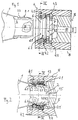
- the ignition lock system comprises an electronic ignition key 1 with a first communication device 3, which facilities for encryption or decryption encoded operating signals, wherein a Part of the electronic ignition key 1 as a plug 2 with molded Unlocking lugs 2.1 and 2.2 notches formed and a less resistant to damage Material is made, as well as an electronic Ignition lock 8 with an ignition lock housing 4, one Key holder 5, which is a socket in the form of a rotating sleeve a second communication device 9 with devices for coding or decoding Operating signals, a trigger fuse 6, which a pair of locking slide with a first frame 6.1, a second frame 6.2 and a first pair of springs 11.1, 11.2, the both frames 6.1, 6.2 from a more resistant to damage Material are made, a turnstile 7, which a pair of locking slides with a third frame 7.1, a fourth frame 7.2 and a second pair of springs 12.1, 12.2 comprises, the two frames 7.1, 7.2 from one against damage more resistant material are made.
- the ignition lock system comprises,
- the electronic Ignition key 1 positioned in front of the electronic ignition lock 8 and the trigger lock 6 and the turnstile 7 are located in their starting positions, d. H.
- the outer contours of the Both frames 6.1 and 6.2 of the trigger safeguard 6 do not protrude beyond the key receptacle 5 designed as a rotating sleeve (See also Fig. 3) and the two frames 7.1 and 7.2 the turnstile 7 are diametrically shifted and each have an end designed as a locking cam both frames 7.1, 7.2 project over the circumference of the rotating sleeve out and engage in recesses 4.3, 4.4 in the housing 4 of the Ignition lock 8, causing a rotary movement of the key holder 5 is prevented.
- the locking cam of the third frame 7.1 engages in the third recess 4.3 and the locking cam of the fourth frame 7.2 engages in the fourth recess 4.4 in the housing 4 of the electronic Ignition lock 8 a.
- the two frames 6.1 and 6.2 of the Trigger protection 6 through the release tabs 2.1 of the connector 2 of the electronic ignition key 1 against the spring force of Spring pairs 11.1, 11.2 diametrically opposite each other from the as Rotating sleeve executed key holder 5 moved and each have an end designed as a locking cam both frames 6.1, 6.2 protrude beyond the circumference of the rotating sleeve out and engage in recesses 4.1, 4.2 in the housing 4 of the Ignition lock 8, the locking cam of the first Frame 6.1 in the first recess 4.1 and the locking cam of the second frame 6.2 in the second recess 4.2 intervenes.
- Fig. 2 shows the essential mechanical parts of the electronic Ignition lock system with a properly in the Key holder 5 inserted electronic ignition key 1, d. H. the part of the electronic designed as plug 2 Ignition key 1 is completely up to the stop 15 in the Key holder 5 introduced.
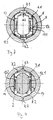
- the two frames 6.1, 6.2 of the trigger safeguard 6 through the properly introduced electronic ignition key 1 by means of the spring force of the spring pair 11.1, 11.2 from the recesses 4.3, 4.4 in the housing 4 of the electronic Ignition lock 8 back into the key holder designed as a rotating sleeve 5 pressed, the inside of the two frames into the notches 2.2 of the connector 2 of the electronic ignition key 1 click into place.
- the deduction protection takes again their starting position as shown in Fig. 1, wherein the starting position with the inserted in the key holder 5 electronic ignition key 1 a locking position corresponds.
- the key holder 5 with the inserted electronic ignition key 1 now from their starting position moved to a position of use, the ignition key 1 not be pulled out of the key holder 5, because the corresponding recesses 4.1, 4.2 in the housing 4 of the ignition lock 8 only in the starting position of the key holder 5 with locking cams of the two frames 6.1, 6.2 of the Deduction protection 6 correspond.
- the two frames 7.1 and 7.2 of the turnstile 7 are through the unlocking lugs 2.1 of the plug 2 of the electronic ignition key 1 against the Spring force of the spring pair 12.1 and 12.2 diametrically against each other shifted and into the rotating sleeve Key holder 5 pressed, the ends of the two frames 7.1, 7.2 are pulled out of the recesses 4.3, 4.4. Consequently is introduced by the properly introduced electronic Key the two frames 7.1, 7.2 in a release position held (see also Fig. 4).
Landscapes
- Engineering & Computer Science (AREA)
- Mechanical Engineering (AREA)
- Lock And Its Accessories (AREA)
- Ignition Installations For Internal Combustion Engines (AREA)
Abstract
Description
- Fig. 1
- Prinzipdarstellung eines Zündschloßsystems mit einem vor dem elektronischen Zündschloß positionierten elektronischen Zündschlüssel
- Fig. 2
- Darstellung eines Zündschloßsystems mit einem vorschriftsmäßig in das elektronische Zündschloß eingeführten elektronischen Zündschlüssel,
- Fig. 3
- Darstellung eines Querschnittes entlang der Schnittlinie III gemäß Fig. 1 durch ein elektronisches Zündschloß,
- Fig. 4
- Darstellung eines Querschnittes entlang der Schnittlinie IV gemäß Fig. 2 durch ein elektronisches Zündschloß mit einem vorschriftsmäßig eingeführten elektronischen Zündschlüssel,
Claims (10)
- Zündschloßsystem für Kraftfahrzeuge, mit einem elektronischen Zündschlüssel und einem elektronischen Zündschloß mit einer Schlüsselaufnahme, wobei der elektronische Zündschlüssel zum Austausch von codierten Betriebssignalen in die Schlüsselaufnahme eingeführt wird, wobei die Schlüsselaufnahme mit dem eingeführten elektronischen Zündschlüssel aus einer Ausgangsstellung in mindestens eine Gebrauchsstellung bewegbar ist, wobei in der Schlüsselaufnahme mechanische Sperrmittel vorgesehen sind, die den elektronischen Zündschlüssel gegen ein Abziehen aus der Schlüsselaufnahme in der mindestens einen Gebrauchsstellung sperren,
dadurch gekennzeichnet,
daß die mechanische Sperrmittel (6; 7) mit dem elektronischen Zündschlüssel (1) so zusammenwirken, daß der elektronische Zündschlüssel (1) und/oder die Schlüsselaufnahme (5) beim gewaltsamen Überwinden von Sperrwirkungen der mechanischen Sperrmittel (6; 7) irreversibel beschädigt wird. - Zündschloßsystem nach Anspruch 1,
dadurch gekennzeichnet,
daß die irreversible Beschädigung durch eine Materialabstimmung zwischen den mechanischen Sperrmitteln (6; 7) und dem elektronischen Zündschlüssel (1) erreicht wird, wobei die mechanischen Sperrmittel (6;7) aus einem gegen Beschädigungen widerstandsfähigeren Material hergestellt wird und ein Gehäuseteil (2) des elektronischen Zündschlüssels (1) aus einem gegen Beschädigungen weniger widerstandsfähigen Material hergestellt wird. - Zündschloßsystem nach Anspruch 1,
dadurch gekennzeichnet,
daß die irreversible Beschädigung durch eine Materialabstimmung zwischen den mechanischen Sperrmitteln (6; 7) und dem elektronischen Zündschlüssel (1) erreicht wird, wobei ein Gehäuseteil (2) des elektronischen Zündschlüssels (1) aus einem gegen Beschädigungen widerstandsfähigeren Material hergestellt wird und die mechanischen Sperrmittel (6; 7) aus einem gegen Beschädigungen weniger widerstandsfähigen Material hergestellt wird. - Zündschloßsystem nach Anspruch 2,
dadurch gekennzeichnet,
daß die irreversible Beschädigung des elektronischen Zündschlüssels (1) deutlich erkennbare Kratzspuren und/oder Bruchstellen in und/oder an Gehäuseteilen (2; 2.1) des elektronischen Zündschlüssels (1) sind. - Zündschloßsystem nach Anspruch 4,
dadurch gekennzeichnet,
daß Sollbruchstellen an vorgegebenen Gehäusestellen (2) des elektronischen Zündschlüssels vorgesehen sind. - Zündschloßsystem nach Anspruch 1, 2 oder 3,
dadurch gekennzeichnet,
daß die mechanischen Sperrmittel (6; 7) als Abzugssicherung (6) und/oder als Drehsperre (7) ausgebildet sind. - Zündschloßsystem nach Anspruch 6,
dadurch gekennzeichnet,
daß die Abzugssicherung (6) als Rastschieberpaar mit einem ersten Rahmen (6.1), einem zweiten Rahmen (6.2) und einem ersten Federpaar (11.1; 11.2) ausgebildet ist und in einem ersten Führungsschacht (13) in einer als Drehhülse ausgeführten Schlüsselaufnahme (5) beweglich gelagert ist, wobei die Abzugssicherung (6) durch ein Zusammenwirken mit einer korrespondierenden Kontur (2.1, 2.2) des Zündschlüssels (1) in eine Sicherungsstellung bringbar ist. - Zündschloßsystem nach Anspruch 7,
dadurch gekennzeichnet,
daß als korrespondierende Kontor Entriegelungsnasen (2.1) und Rastkerben (2.2) am Zündschlüssel vorgesehen sind, wobei die Entriegelungsnasen (2.1) beim Einführen des elektronischen Zündschlüssels (1) in die Schlüsselaufnahme (5) die beiden Rahmen (6.1; 6.2) gegen die Kraft des ersten Federpaars (11.1, 11.2) diametral gegeneinander verschieben und die Verriegelungsnocken der beiden Rahmen (6.1, 6.2) in Ausnehmungen (4.1, 4.2) im Gehäuse (4) des elektronischen Zündschlosses (8) drücken, wobei die beiden Rahmen (6.1, 6.2) bei einem vorschriftsmäßig eingeführten Zündschlüssel (1) durch die Federkraft des ersten Federpaars (11.1; 11.2) in die hinter den Entriegelungsnasen (2.1) angeordneten Rastkerben (2.2) gedrückt werden und somit Verriegelungsnocken der beiden Rahmen (6.1, 6.2) wieder aus den Ausnehmungen (4.1, 4.2) gezogen werden und die beiden Rahmen (6.1, 6.2) die Sicherungsstellung einnehmen, wobei die Abzugssicherung (6) nur in der Ausgangsstellung der Schlüsselaufnahme (5) aus der Sicherungsstellung in eine Entsicherungsstellung bewegbar ist. - Zündschloßsystem nach Anspruch 6,
dadurch gekennzeichnet,
daß die Drehsperre (7) als Sperrschieberpaar mit einem dritten Rahmen (7.1), einem vierten Rahmen (7.2) und einem zweiten Federpaar (12.1; 12.2) ausgebildet ist und in einem zweiten Führungsschacht (14) in der als Drehhülse ausgeführten Schlüsselaufnahme (5) beweglich gelagert ist, wobei die Drehsperre (7) durch ein Zusammenwirken mit einer korrespondierenden Kontur (2.1) des Zündschlüssels (1) entriegelbar ist. - Zündschloßsystem nach Anspruch 9,
dadurch gekennzeichnet,
daß in der Ausgangsstellung der Schlüsselaufnahme (5) ohne eingeführten elektronischen Zündschlüssel (1) die beiden Rahmen (7.1, 7.2) diametral gegeneinander verschoben sind und die Verriegelungsnocken der beiden Rahmen (7.1, 7.2) aus der Schlüsselaufnahme (5) herausragen und in Ausnehmungen (4.3, 4.4) im Gehäuse (4) des elektronischen Zündschlosses (8) eingreifen, wodurch die Schlüsselaufnahme (5) gegen eine Bewegung aus der Ausgangsstellung in wenigstens eine Gebrauchsstellung gesperrt wird, und daß Entriegelungsnasen (2.1) an den elektronischen Zündschlüssel (1) angeformt sind, welche bei einem vorschriftsmäßig eingeführten elektronischen Zündschlüssel (1) die beiden Rahmen (7.1, 7.2) gegen die Federkraft des zweiten Federpaars (12.1; 12.2) diametral gegeneinander in die Schlüsselaufnahme (5) verschieben und so die Enden der beiden Rahmen (7.1, 7.2) aus den Ausnehmungen (4.3, 4.4) im Gehäuse (4) des elektronischen Zündschlosses (8) gezogen werden.
Applications Claiming Priority (2)
| Application Number | Priority Date | Filing Date | Title |
|---|---|---|---|
| DE19839347A DE19839347C1 (de) | 1998-08-28 | 1998-08-28 | Zündschloßsystem für Kraftfahrzeuge |
| DE19839347 | 1998-08-28 |
Publications (3)
| Publication Number | Publication Date |
|---|---|
| EP0982203A2 true EP0982203A2 (de) | 2000-03-01 |
| EP0982203A3 EP0982203A3 (de) | 2003-03-26 |
| EP0982203B1 EP0982203B1 (de) | 2006-12-20 |
Family
ID=7879121
Family Applications (1)
| Application Number | Title | Priority Date | Filing Date |
|---|---|---|---|
| EP99114752A Revoked EP0982203B1 (de) | 1998-08-28 | 1999-07-28 | Zündschlosssystem für Kraftfahrzeuge |
Country Status (4)
| Country | Link |
|---|---|
| US (1) | US6546768B1 (de) |
| EP (1) | EP0982203B1 (de) |
| JP (1) | JP2000135970A (de) |
| DE (1) | DE19839347C1 (de) |
Cited By (1)
| Publication number | Priority date | Publication date | Assignee | Title |
|---|---|---|---|---|
| DE102005018494A1 (de) * | 2005-04-21 | 2006-10-26 | Daimlerchrysler Ag | Fahrberechtigungssystem, insbesondere für ein Kraftfahrzeug |
Families Citing this family (33)
| Publication number | Priority date | Publication date | Assignee | Title |
|---|---|---|---|---|
| DE19943498C2 (de) * | 1999-09-10 | 2002-03-07 | Kiekert Ag | Fahrzeugschlüssel für fernbedienbare Fahrzeugschliesssysteme |
| DE10000857A1 (de) * | 2000-01-12 | 2001-07-19 | Daimler Chrysler Ag | Verfahren zur Inbetriebnahme eines motorangetriebenen Kraftfahrzeugs |
| DE10034350B4 (de) * | 2000-07-14 | 2004-04-01 | Conti Temic Microelectronic Gmbh | System zum Betrieb eines motorangetriebenen Kraftfahrzeugs |
| DE10147031B4 (de) * | 2000-09-27 | 2012-11-29 | Marquardt Gmbh | Zündschloß für ein Kraftfahrzeug |
| US20040050122A1 (en) * | 2002-09-13 | 2004-03-18 | Mitchell Ernst Kern | Non-planar key shaped electronic key |
| US7392675B2 (en) * | 2002-11-08 | 2008-07-01 | Kabushiki Kaisha Tokai Rika Denki Seisakusho | Slot mechanism and smart ignition system |
| JP4391767B2 (ja) * | 2003-06-03 | 2009-12-24 | 株式会社東海理化電機製作所 | エンジン始動スイッチ及び携帯機 |
| DE102004019919B3 (de) * | 2004-04-21 | 2006-02-02 | Huf Hülsbeck & Fürst Gmbh & Co. Kg | Vorrichtung zum Starten eines Fahrzeugmotors mittels eines elektronischen Schlüssels und ein dazu zu verwendener Schlüssel |
| US7119667B2 (en) * | 2004-06-28 | 2006-10-10 | Delphi Technologies, Inc. | Integrated electronic security system for vehicle |
| WO2006100629A2 (en) * | 2005-03-21 | 2006-09-28 | Nxp B.V. | Filter device, circuit arrangement comprising such filter device as well as method of operating such filter device |
| KR20060102637A (ko) * | 2005-03-24 | 2006-09-28 | 김갑식 | 전자식 록장치 |
| US20060220458A1 (en) * | 2005-04-05 | 2006-10-05 | Feldman Mark G | Keyless ignition module for an automotive vehicle |
| DE102005016649A1 (de) * | 2005-04-12 | 2006-10-19 | Huf Hülsbeck & Fürst Gmbh & Co. Kg | Vorrichtung zum Starten und zum Betrieb eines Motors in einem Kraftfahrzeug |
| US20060266089A1 (en) * | 2005-05-26 | 2006-11-30 | Dimig Steven J | Hybrid key |
| US20070241862A1 (en) * | 2006-04-12 | 2007-10-18 | Dimig Steven J | Transponder authorization system and method |
| KR100741322B1 (ko) | 2006-04-25 | 2007-07-23 | 조창래 | 이륜 자동차용 전자 시동키 |
| US7617708B2 (en) * | 2006-07-28 | 2009-11-17 | Volkswagen Ag | Ignition lock for a motor vehicle and method of operating an ignition lock system |
| CN101636157A (zh) * | 2007-01-12 | 2010-01-27 | 康乃尔研究基金会有限公司 | 作为抗菌干预的新型靶的腺苷酰环化酶 |
| US7334441B1 (en) | 2007-01-16 | 2008-02-26 | Lear Corporation | Electronic vehicle key and housing assembly |
| KR100856580B1 (ko) | 2007-06-26 | 2008-09-04 | 양재우 | 전동제어형 자동차 이그니션 노브 록 장치 및 그의록킹방법 |
| JP4971084B2 (ja) * | 2007-09-12 | 2012-07-11 | 株式会社東海理化電機製作所 | バレットキー収納装置 |
| JP4971083B2 (ja) * | 2007-09-12 | 2012-07-11 | 株式会社東海理化電機製作所 | バレットキー収納装置 |
| DE102008007121A1 (de) * | 2008-02-01 | 2009-08-06 | Marquardt Gmbh | Zündschloß für ein Kraftfahrzeug |
| DE102008010473A1 (de) * | 2008-02-21 | 2009-08-27 | Conti Temic Microelectronic Gmbh | Lesevorrichtung zur Aufnahme eines Kraftfahrzeugschlüssels |
| KR100974547B1 (ko) * | 2008-05-27 | 2010-08-11 | 현대자동차주식회사 | 이모빌라이저 시스템의 키 로킹장치 |
| JP5038238B2 (ja) * | 2008-06-12 | 2012-10-03 | 株式会社東海理化電機製作所 | 車両機能制限システム |
| WO2010004235A1 (en) * | 2008-07-07 | 2010-01-14 | Talaris Holdings Limited | Key, lock assembly and method of actuating a lock |
| US8487743B2 (en) * | 2008-08-18 | 2013-07-16 | GM Global Technology Operations LLC | Valet keyfob system |
| JP5296470B2 (ja) * | 2008-09-24 | 2013-09-25 | 株式会社東海理化電機製作所 | 車内補助キーのキー保持装置 |
| JP2012017075A (ja) * | 2010-07-09 | 2012-01-26 | Tokai Rika Co Ltd | エンジン始動装置 |
| US8474289B2 (en) | 2011-11-28 | 2013-07-02 | Southern Company Services, Inc. | Locking systems |
| TWM447912U (zh) * | 2012-10-26 | 2013-03-01 | Lintex Co Ltd | 索線頭鎖扣結構 |
| US9206627B2 (en) * | 2012-10-26 | 2015-12-08 | Lintex Co., Ltd. | Engagement structure for a cable head |
Citations (1)
| Publication number | Priority date | Publication date | Assignee | Title |
|---|---|---|---|---|
| DE3306863A1 (de) | 1983-02-26 | 1984-09-06 | Daimler-Benz Ag, 7000 Stuttgart | Schlosssystem fuer kraftfahrzeuge, insbesondere lenkschlosssystem |
Family Cites Families (20)
| Publication number | Priority date | Publication date | Assignee | Title |
|---|---|---|---|---|
| US1295351A (en) * | 1918-08-23 | 1919-02-25 | Lyttleton F Morgan | Key. |
| US1789757A (en) * | 1926-01-13 | 1931-01-20 | Briggs & Stratton Corp | Tumbler lock |
| US3418833A (en) * | 1966-08-15 | 1968-12-31 | Chicago Lock Co | Tamperproof cylinder lock |
| FR2041574A5 (de) * | 1969-04-30 | 1971-01-29 | Neiman Exploitation Brevets | |
| JPS519218B1 (de) * | 1969-11-24 | 1976-03-25 | ||
| GB1297747A (de) * | 1970-05-12 | 1972-11-29 | ||
| US3789636A (en) * | 1971-03-16 | 1974-02-05 | Tokai Rika Co Ltd | Device in an automobile for preventing an accidental locking of a steering shaft |
| DE2349182A1 (de) * | 1973-09-29 | 1975-04-03 | Volkswagenwerk Ag | Zylinderschlossanordnung |
| US4074547A (en) * | 1976-12-08 | 1978-02-21 | General Motors Corporation | Lock cylinder assembly |
| DE2704478C2 (de) * | 1977-02-03 | 1989-02-23 | Dr.Ing.H.C. F. Porsche Ag, 7000 Stuttgart | Diebstahlsicherungssystem für Kraftfahrzeuge |
| DE2708141C2 (de) * | 1977-02-25 | 1985-02-07 | Zeiss Ikon Ag, 7000 Stuttgart | Zylinderschloß mit Meldung von Auftast- und Aufbohrversuchen |
| DE2936402C2 (de) * | 1979-09-08 | 1986-03-06 | Kiekert GmbH & Co KG, 5628 Heiligenhaus | Schließanlage für Kraftfahrzeug-Türverschlüsse |
| US4898010A (en) * | 1987-10-28 | 1990-02-06 | Nissan Motor Company, Limited | Keyless entry system for automotive vehicles |
| JPH0439144A (ja) * | 1990-06-04 | 1992-02-10 | Nippon Denshi Lock Kk | 車輌のキー抜き忘れ警報装置 |
| DE4317116C2 (de) * | 1993-05-21 | 1997-03-20 | Audi Ag | Diebstahlschutzeinrichtung als Immobilisationseinrichtung an einem Kraftfahrzeug |
| DE4434655C2 (de) * | 1993-10-01 | 1999-08-26 | Marquardt Gmbh | Elektronisches Zündstartschloßsystem an einem Kraftfahrzeug |
| JP3585550B2 (ja) * | 1994-02-03 | 2004-11-04 | 本田技研工業株式会社 | 車両用キースイッチ装置 |
| US5551267A (en) * | 1994-04-15 | 1996-09-03 | Briggs & Stratton Corporation | Anti-magnetic tampering system for automobile ignition lock |
| DE19520211A1 (de) * | 1994-06-03 | 1996-02-01 | Strattec Security Corp | Elektronische Verriegelungsanordnung für ein Schloßsystem |
| DE19751805C1 (de) * | 1997-11-24 | 1998-10-29 | Daimler Benz Ag | Elektronisches Zündschloßsystem, insbesondere für Kraftfahrzeuge |
-
1998
- 1998-08-28 DE DE19839347A patent/DE19839347C1/de not_active Expired - Fee Related
-
1999
- 1999-07-28 EP EP99114752A patent/EP0982203B1/de not_active Revoked
- 1999-08-18 JP JP26758199A patent/JP2000135970A/ja active Pending
- 1999-08-30 US US09/385,370 patent/US6546768B1/en not_active Expired - Fee Related
Patent Citations (1)
| Publication number | Priority date | Publication date | Assignee | Title |
|---|---|---|---|---|
| DE3306863A1 (de) | 1983-02-26 | 1984-09-06 | Daimler-Benz Ag, 7000 Stuttgart | Schlosssystem fuer kraftfahrzeuge, insbesondere lenkschlosssystem |
Cited By (1)
| Publication number | Priority date | Publication date | Assignee | Title |
|---|---|---|---|---|
| DE102005018494A1 (de) * | 2005-04-21 | 2006-10-26 | Daimlerchrysler Ag | Fahrberechtigungssystem, insbesondere für ein Kraftfahrzeug |
Also Published As
| Publication number | Publication date |
|---|---|
| EP0982203B1 (de) | 2006-12-20 |
| JP2000135970A (ja) | 2000-05-16 |
| US6546768B1 (en) | 2003-04-15 |
| DE19839347C1 (de) | 1999-12-02 |
| EP0982203A3 (de) | 2003-03-26 |
Similar Documents
| Publication | Publication Date | Title |
|---|---|---|
| EP0982203A2 (de) | Zündschlosssystem für Kraftfahrzeuge | |
| DE3436761A1 (de) | Sicherheitseinrichtung gegen unbefugten betrieb eines kraftfahrzeuges | |
| DE9208698U1 (de) | Lenkradschloß | |
| DE102018009217A1 (de) | Verriegelungseinrichtung mit Zuhaltung für Schutztüren | |
| DE102010037071A1 (de) | Vorrichtung zur Verlagerung eines bewegbaren Sperrelementes | |
| DE19751805C1 (de) | Elektronisches Zündschloßsystem, insbesondere für Kraftfahrzeuge | |
| EP1135284B1 (de) | Schliessystem, insbesondere für kraftfahrzeuge | |
| DE4446613A1 (de) | Lenkradverriegelung an einem Kraftfahrzeug | |
| DE2853655A1 (de) | Zylinderschloss mit schluessel zur mechanischen und/oder elektromechanischen verriegelung | |
| DE19940247A1 (de) | Schließeinrichtung | |
| DE102018003614A1 (de) | Verriegelungseinrichtung, insbesondere für ein Kraftfahrzeug | |
| DE19653860C1 (de) | Schließsystem für Kraftfahrzeuge | |
| DE10107992B4 (de) | Zündschloßsystem für ein Kraftfahrzeug | |
| DE3941068C2 (de) | ||
| EP0281507B1 (de) | Doppelschliesszylinder | |
| DE3224630C2 (de) | Schließzylinder, insbesondere für Kraftfahrzeug-Lenkschlösser | |
| EP0520154A1 (de) | Anordnung eines Kabelschlosses an einem Zweiradrahmen | |
| DE19951986C1 (de) | Elektronischer Zündanlassschalter für Kraftfahrzeuge | |
| DE19838992A1 (de) | Zündanlaßschalter für Kraftfahrzeuge mit elektronischer Lenkungsverriegelung | |
| DE1640157B1 (de) | Schluesselbetaetigter elektrischer Schalter fuer Kraftfahrzeuge | |
| DE2606698A1 (de) | Schloss | |
| AT524794B1 (de) | Zylinderschloss | |
| DE102012112429A1 (de) | Handhabe für eine Schließvorrichtung eines Kraftfahrzeuges, mit einer Massensperre, die wirkende Beschleunigungen aus unterschiedlichen Richtungen berücksichtigt | |
| DE2615912B2 (de) | Schlüsselbetätigte Diebstahlsicherung für Kraftfahrzeuge | |
| EP3453579B1 (de) | Verriegelungsvorrichtung |
Legal Events
| Date | Code | Title | Description |
|---|---|---|---|
| PUAI | Public reference made under article 153(3) epc to a published international application that has entered the european phase |
Free format text: ORIGINAL CODE: 0009012 |
|
| AK | Designated contracting states |
Kind code of ref document: A2 Designated state(s): AT BE CH CY DE DK ES FI FR GB GR IE IT LI LU MC NL PT SE |
|
| AX | Request for extension of the european patent |
Free format text: AL;LT;LV;MK;RO;SI |
|
| PUAL | Search report despatched |
Free format text: ORIGINAL CODE: 0009013 |
|
| AK | Designated contracting states |
Kind code of ref document: A3 Designated state(s): AT BE CH CY DE DK ES FI FR GB GR IE IT LI LU MC NL PT SE Designated state(s): AT BE CH CY DE DK ES FI FR GB GR IE IT LI LU MC NL PT SE |
|
| AX | Request for extension of the european patent |
Extension state: AL LT LV MK RO SI |
|
| 17P | Request for examination filed |
Effective date: 20030215 |
|
| 17Q | First examination report despatched |
Effective date: 20030801 |
|
| AKX | Designation fees paid |
Designated state(s): ES FR GB IT |
|
| REG | Reference to a national code |
Ref country code: DE Ref legal event code: 8566 |
|
| GRAP | Despatch of communication of intention to grant a patent |
Free format text: ORIGINAL CODE: EPIDOSNIGR1 |
|
| GRAS | Grant fee paid |
Free format text: ORIGINAL CODE: EPIDOSNIGR3 |
|
| GRAA | (expected) grant |
Free format text: ORIGINAL CODE: 0009210 |
|
| AK | Designated contracting states |
Kind code of ref document: B1 Designated state(s): ES FR GB IT |
|
| PG25 | Lapsed in a contracting state [announced via postgrant information from national office to epo] |
Ref country code: IT Free format text: LAPSE BECAUSE OF FAILURE TO SUBMIT A TRANSLATION OF THE DESCRIPTION OR TO PAY THE FEE WITHIN THE PRESCRIBED TIME-LIMIT;WARNING: LAPSES OF ITALIAN PATENTS WITH EFFECTIVE DATE BEFORE 2007 MAY HAVE OCCURRED AT ANY TIME BEFORE 2007. THE CORRECT EFFECTIVE DATE MAY BE DIFFERENT FROM THE ONE RECORDED. Effective date: 20061220 |
|
| REG | Reference to a national code |
Ref country code: GB Ref legal event code: FG4D Free format text: NOT ENGLISH |
|
| PG25 | Lapsed in a contracting state [announced via postgrant information from national office to epo] |
Ref country code: ES Free format text: LAPSE BECAUSE OF FAILURE TO SUBMIT A TRANSLATION OF THE DESCRIPTION OR TO PAY THE FEE WITHIN THE PRESCRIBED TIME-LIMIT Effective date: 20070331 |
|
| RAP2 | Party data changed (patent owner data changed or rights of a patent transferred) |
Owner name: DAIMLERCHRYSLER AG |
|
| ET | Fr: translation filed | ||
| GBV | Gb: ep patent (uk) treated as always having been void in accordance with gb section 77(7)/1977 [no translation filed] |
Effective date: 20061220 |
|
| PLBI | Opposition filed |
Free format text: ORIGINAL CODE: 0009260 |
|
| PLAX | Notice of opposition and request to file observation + time limit sent |
Free format text: ORIGINAL CODE: EPIDOSNOBS2 |
|
| 26 | Opposition filed |
Opponent name: VOLKSWAGEN AG Effective date: 20070920 |
|
| PG25 | Lapsed in a contracting state [announced via postgrant information from national office to epo] |
Ref country code: GB Free format text: LAPSE BECAUSE OF FAILURE TO SUBMIT A TRANSLATION OF THE DESCRIPTION OR TO PAY THE FEE WITHIN THE PRESCRIBED TIME-LIMIT Effective date: 20061220 |
|
| RAP2 | Party data changed (patent owner data changed or rights of a patent transferred) |
Owner name: DAIMLER AG |
|
| PLBB | Reply of patent proprietor to notice(s) of opposition received |
Free format text: ORIGINAL CODE: EPIDOSNOBS3 |
|
| RDAF | Communication despatched that patent is revoked |
Free format text: ORIGINAL CODE: EPIDOSNREV1 |
|
| RDAF | Communication despatched that patent is revoked |
Free format text: ORIGINAL CODE: EPIDOSNREV1 |
|
| PGFP | Annual fee paid to national office [announced via postgrant information from national office to epo] |
Ref country code: FR Payment date: 20080715 Year of fee payment: 10 |
|
| RDAG | Patent revoked |
Free format text: ORIGINAL CODE: 0009271 |
|
| STAA | Information on the status of an ep patent application or granted ep patent |
Free format text: STATUS: PATENT REVOKED |
|
| 27W | Patent revoked |
Effective date: 20081117 |