EP0982209B1 - Dispositif de freinage, en particulier pour des trains de grande longueur - Google Patents
Dispositif de freinage, en particulier pour des trains de grande longueur Download PDFInfo
- Publication number
- EP0982209B1 EP0982209B1 EP99104427A EP99104427A EP0982209B1 EP 0982209 B1 EP0982209 B1 EP 0982209B1 EP 99104427 A EP99104427 A EP 99104427A EP 99104427 A EP99104427 A EP 99104427A EP 0982209 B1 EP0982209 B1 EP 0982209B1
- Authority
- EP
- European Patent Office
- Prior art keywords
- brake
- pressure
- control
- braking system
- brake pipe
- Prior art date
- Legal status (The legal status is an assumption and is not a legal conclusion. Google has not performed a legal analysis and makes no representation as to the accuracy of the status listed.)
- Expired - Lifetime
Links
Images


Classifications
-
- B—PERFORMING OPERATIONS; TRANSPORTING
- B60—VEHICLES IN GENERAL
- B60T—VEHICLE BRAKE CONTROL SYSTEMS OR PARTS THEREOF; BRAKE CONTROL SYSTEMS OR PARTS THEREOF, IN GENERAL; ARRANGEMENT OF BRAKING ELEMENTS ON VEHICLES IN GENERAL; PORTABLE DEVICES FOR PREVENTING UNWANTED MOVEMENT OF VEHICLES; VEHICLE MODIFICATIONS TO FACILITATE COOLING OF BRAKES
- B60T17/00—Component parts, details, or accessories of power brake systems not covered by groups B60T8/00, B60T13/00 or B60T15/00, or presenting other characteristic features
- B60T17/18—Safety devices; Monitoring
- B60T17/22—Devices for monitoring or checking brake systems; Signal devices
- B60T17/228—Devices for monitoring or checking brake systems; Signal devices for railway vehicles
-
- B—PERFORMING OPERATIONS; TRANSPORTING
- B60—VEHICLES IN GENERAL
- B60T—VEHICLE BRAKE CONTROL SYSTEMS OR PARTS THEREOF; BRAKE CONTROL SYSTEMS OR PARTS THEREOF, IN GENERAL; ARRANGEMENT OF BRAKING ELEMENTS ON VEHICLES IN GENERAL; PORTABLE DEVICES FOR PREVENTING UNWANTED MOVEMENT OF VEHICLES; VEHICLE MODIFICATIONS TO FACILITATE COOLING OF BRAKES
- B60T13/00—Transmitting braking action from initiating means to ultimate brake actuator with power assistance or drive; Brake systems incorporating such transmitting means, e.g. air-pressure brake systems
- B60T13/10—Transmitting braking action from initiating means to ultimate brake actuator with power assistance or drive; Brake systems incorporating such transmitting means, e.g. air-pressure brake systems with fluid assistance, drive, or release
- B60T13/66—Electrical control in fluid-pressure brake systems
- B60T13/665—Electrical control in fluid-pressure brake systems the systems being specially adapted for transferring two or more command signals, e.g. railway systems
Definitions
- the present invention relates to an air braking system according to the preamble of claim 1, in particular for very long trains.
- the invention has been developed in particular in view of the application on goods trains longer than one kilometre but the invention can be equally applied also on trains considerably shorter, such as passenger trains.
- the braking system most used at international level is based on the operating principle of the Westinghouse air brake.
- This braking system comprises a compressed air main reservoir placed on the locomotive and fed by a compressor at a reference pressure of 5 bar.
- a brake pipe starts from the main reservoir and extends along all the vehicles of the train.
- a control cock placed on the locomotive allows the pressure in the brake pipe to be reduced with respect to the reference pressure and a plurality of braking apparatus placed on the various vehicles of the train produce a braking force correlated to the difference between the pressure in the brake pipe and the reference pressure.
- the brake pipe carries out both the function of transmitting to the vehicles the energy necessary for activating the brakes and the function of transmitting the braking command.
- the energy is accumulated in a plurality of auxiliary reservoirs placed on the various vehicles which are filled at a pressure equal to the reference pressure of the brake pipe.
- the braking command is given by reducing the pressure in the brake pipe.
- a distributor is provided on each vehicle, which puts the auxiliary reservoir in communication with brake actuating cylinders when the pressure in the brake pipe falls below the reference pressure (which is usually 5 bar).
- WO-A-98/09857 discloses a braking system having the features of the pre-characterising portion of claim 1.
- This document discloses an electropneumatic brake control valve unit capable of operating at the interface of the emergency brake portion or the service brake portion of a standard brake control valve as retrofit unit or operating as a stand alone electropneumatic unit.
- the unit includes electric valves responsive to electrical signals and sensed brake pipe pressures to operate pneumatic valves to control the brake cylinder.
- the pneumatic valves are also operable independent of electric control valves so as to allow braking with the electrical control off or disabled.
- the present invention relates to a braking system having the features forming the subject of the main claim.
- the present invention is essentially based on the idea of using, in addition to a standard braking system, which remains essentially the same, a new braking system which preferably operates with a higher pressure in the brake pipe and, consequently, in the various auxiliary reservoirs (for instance 7 bar).
- a new braking system which preferably operates with a higher pressure in the brake pipe and, consequently, in the various auxiliary reservoirs (for instance 7 bar).
- the control reservoirs of the various distributors installed on the vehicles of the train are all filled at a pressure lower than the normal operating pressure of the brake pipe (for instance at 5.4 bar).
- the distributor behaves like a normal pneumatic distributor of the type compliant to U.I.C.
- the pressure in the brake pipe can be maintained at the value prescribed by U.I.C. standards.
- the braking is controlled by the electrically controlled section of the distributors and in this case the pneumatically controlled section does never become operative.
- the braking system is fully compatible with present standards and, in case of failure of the electrically controlled system, it can operate as a normal braking system with air control.
- the braking system according to the invention is characterized by a much faster propagation of the brake command along the train and by reaction times of the braking system considerably faster. This permits the train to travel at speeds considerably higher and the braking system does not render the train uncontrollable.
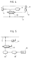
- the reference number 10 indicates a train formed by a locomotive M and by a plurality of vehicles coupled to each other, indicated V 1 , V 2 , V 3 , ... V n .
- the train 10 is provided with a pneumatic braking system including a brake pipe 12 which extends from the locomotive to the last vehicle of the train.
- the braking system comprises essentially a main reservoir 14 (dedicated to the braking system) arranged on the locomotive M and connected to the brake pipe 12 by a control cock 16.
- a braking assembly is arranged on each vehicle V 1 , V 2 , V 3 , ... V n and includes, in a way per se known, a distributor 18 pneumatically connected to the brake pipe 12, to an auxiliary reservoir 40 and to one or more brake cylinders 22 mechanically connected to the brake control linkage.
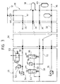
- FIG. 2 shows a partial pneumatic diagram of a brake control system according to the invention, indicated all together at 18.
- the control system 18 comprises a pneumatically controlled section 24, an electrically controlled section 26 and a support 28 of the distributor.
- the pneumatically controlled section 24 performs the same function as a normal pneumatic distributor for railway brakes homologated in accordance with the U.I.C. standards.
- the pneumatically controlled section 24 has not been shown in detail in the figures in that it is constructively and functionally equivalent to a known pneumatic distributor and its constructive features lie outside the scope of the present invention.
- the pneumatically controlled section 24, as any U.I.C. standard distributor has an inlet 30 for the connection to the brake pipe 12 and an outlet 32 for the connection to the brake cylinders 22.
- the section 24 further comprises two connection points indicated at 34 and 36 for the connection, respectively, to a control reservoir 38 and to an auxiliary reservoir 40.
- the pneumatic control section 24 (constructively identical to a U.I.C. standard distributor) is directly connected to the support 28 of the distributor, so that its inlet 30 is connected to the brake pipe 12 by a line 42 and by an on/off valve 44, its outlet 32 is connected to the line 46 which feeds the brake cylinders (on which an accumulator 48 can be branched) and the connection points 34 and 36 are directly connected to the control reservoir 38 and to the auxiliary reservoir 40.
- the pneumatic control section 24 is realised such that when the pressure in the inlet line 30 is higher than the pressure on the connection point 34, the pressure on the outlet line 32 is zero.
- the brake pipe 12 is filled at a pressure of 5 bar and the pneumatic distributor fills the control reservoir 38 and the auxiliary reservoir 40 at a pressure substantially equal to the pressure in the brake pipe 12.
- the braking command is given by operating the control cock 16 placed on the locomotive M (figure 1) which determines a depression which propagates along the brake pipe 12. The depression along the brake pipe forms the braking command.
- the distributor detects a drop of pressure in the brake pipe with respect to the pressure existing in the control reservoir 38, it puts the auxiliary reservoir 40 in communication with the line 32 feeding the brake cylinders.
- each control system 18 comprises an electrically controlled section 26.
- the electrically controlled section 26 is carried by an intermediate bracket physically placed between the support 28 of the distributor and the pneumatically controlled section 24.
- the electrically controlled section 26 comprises a line 30 which puts the inlet fitting 42 of the support 28 of the distributor in communication with the inlet 30 of the pneumatically controlled section 24.
- An electrically controlled application valve is branched on the line 50.
- the application valve 53 is normally close and in open condition it puts the line 50 in communication with the atmosphere.
- a transducer 52 and a pressure switch 54 are also placed on the line 50.
- the electrically controlled section 26 comprises a second line 56 which connects the connection point 34 of the pneumatically controlled section to the control reservoir 38 and a third line 58 which connects the connection point 36 to the auxiliary reservoir 40.
- a pressure control valve calibrated at a pressure lower than the pressure in the brake pipe 12 is placed on the line 56.
- a check valve 62 is connected in parallel to the pressure control valve 60 and enables the passage of a flow of pressurised air directed from the control reservoir 38 to the connection point 34. When it is desired to operate at a pressure in the brake pipe 12 in accordance with the U.I.C. standards, the pressure control valve 60 and the check valve 62 are not necessary.
- connection points 34, 36 of the pneumatically controlled section 24 are placed in fluid communication with the inlet line 30, which is in communication with the brake pipe 12.
- the auxiliary reservoir 40 is filled at a pressure substantially equal to the pressure of the brake pipe 12, whereas the control reservoir 38 is loaded at a pressure equal to the calibrating pressure of the pressure control valve 60.
- the braking system according to the present invention is designed for operating with a constant pressure in the brake pipe 12, for instance of 7 bar.
- the pressure control valve 60 can be calibrated at a value of 5.4 bar. Therefore, the auxiliary reservoir 40 is filled at 7 bar whereas the control reservoir 38 is filled at 5.8 bar.
- the braking system can also operate at a pressure in the brake pipe of 5 bar (U.I.C. standards) and in this case both the control reservoir 38 and the auxiliary reservoir 40 are loaded at 5 bar.
- the electrically controlled section 26 of the distributor 18 comprises also a brake valve assembly including a brake valve 64, a brake-release valve 66 and a pressure transducer 78.
- the brake valve is electrically controlled and is branched on the line 58 connected to the auxiliary reservoir 40.
- the brake valve 64 is normally closed and is connected to an electrically controlled brake-release valve 66 which is normally open. When the brake-release valve 66 is open, it puts the line 68 in communication with the atmosphere.
- a double stop valve 70 has a first inlet connected to the outlet 32 of the pneumatic section 24, a second inlet connected to the line 68 disposed downstream of the brake valve 64 and an outlet 72 connected to the line 46 which feeds the brake cylinders.
- a further pressure transducer 76 is connected to the outlet 32 of the pneumatic section 24.
- the pressure transducer 78 is connected downstream of the brake valve 64 and detects the pressure at the outlet of the valve assembly.
- valves of the electrically controlled section 26 are controlled by an electronic control unit (not shown) associated with the control system 18 which receives braking or brake-releasing commands from a remote unit 80 placed on the locomotive M (figure 1).
- the central control unit 80 of the braking system can be associated with a radio transmitter which emits braking or brake-releasing commands in the form of radio signals which are picked up by receivers placed on the electronic units aboard the vehicles. Such radio signals are converted into electric signals for controlling the valves.
- the transducers 52, 76 and 78 detect the value of pressure in the corresponding points of the pneumatic circuit and send to the electronic control unit corresponding electric signals which are used by the control unit for varying the time of aperture of the valves 64, 66.
- the commands could be transmitted via cable, by means of a serial bus which extends along all the vehicles of the train.
- Two independent busses could be provided, a first one dedicated to the transmission of braking and brake-releasing commands and the other one dedicated to the transmission of diagnostic information.
- the second bus could be used for the transmission of the command signals, temporarily renouncing to the transmission of the diagnostic information.
- An important feature of the braking system according to the invention consists in that the same braking system can operated either with pneumatic control in accordance with U.I.C. standards or with electric control.
- pneumatic control in accordance with U.I.C. standards or with electric control.
- a unit 82 operates a valve 84 which interrupts the connection between the cock 16 and the brake pipe 12 and connects the brake pipe 12 to the main reservoir 14 through a pressure control valve (not shown) calibrated, for instance, either at 7 bar or at 5 bar.
- the braking commands are no more given through the control cock 16 but through the central control unit 80 of the braking system which is connected via radio or via cable to the control units of the individual control systems of the vehicles.
- the control unit of a vehicle When the control unit of a vehicle receives a braking command, it opens the brake valve 64 and at the same time closes the brake-release valve 66.
- the pneumatic control section 24 is either deactivated or inoperative when the pressure in the brake pipe 12 is equal to or higher than the pressure in the control reservoir 38.
- the brake valve 64 is open, it puts the auxiliary reservoir 40 in communication with the brake cylinders through the lines 72 and 46.
- the signals provided by the transducer 78 allow the control unit to modulate the time of aperture of the valves 64, 66 for obtaining the desired value of the brake pressure.
- the valve 64 In the condition of brake-release, the valve 64 is closed and the brake-valve 66 is open, and in this condition the brake cylinders are therefore put in communication with the atmosphere through the lines 46, 72 and through the brake-release valve 66.
- the same braking system can also operate with pneumatic control in accordance with the U.I.C. standards. For operating in this manner, it is sufficient to turn the lever of the control cock 16 to the pneumatic control position.
- the unit 82 brings back the valve 84 to its rest position in which it puts the control cock 16 in communication with the brake pipe 12.
- By operating the cock 16 a depression is produced in the brake pipe 12 which propagates from the locomotive to the last vehicle of the train.
- a drop of pressure in the brake pipe 12 automatically produces the intervention of the pneumatic control section 24 of each control system 18.
- the pneumatic control section 24 puts the connection point 36 in communication with the outlet 32.
- a braking pressure is thereby produced, which is transmitted to the brake cylinders through the line 86, the double stop valve 70, the line 72 and the line 46.
- the transducer 76 detects the fact that the distributor 18 is in the pneumatic control condition. By comparing the values of pressure detected by the transducer 52 and 76 it is possible to obtain information about the correct operation of the pneumatic control section 24.
- the transducer 52 can also be used for carrying out the function of automatically determining the composition of the train, as disclosed in detail in EP-A-968 897 of the same Applicant.
- the electric power necessary for the operation of the electrically controlled section 26 comes from a battery 86 integrated or placed in close proximity to the control system 18.
- the battery 86 is charged by a small electric generator 88 driven by a small compressed air turbine 90.
- the pressure switch 54 enables the activation of the turbine 90 by activating a normally open valve 92 only when the pressure in the brake pipe is greater that 5.5 bar.
- the valve 92 can be manually operated.
- FIG. 3 shows the pneumatic diagram of a variant of the control system according to the invention.
- the elements corresponding to those previously disclosed are indicated by the same numeral references.
- the electrically-controlled section 26 is housed in the cover of a standard U.I.C. distributor which forms the pneumatically controlled section 24. Therefore, the pneumatically controlled section is directly connected to the support 28 of the distributor, whereas the electrically controlled section 26 is housed in the cover of the distributor instead of being placed on an intermediate bracket.
- the pressure control valve 60 and the associated check valve 62 are missing from the electrically controlled section 26, the pneumatically controlled section 24 being realised so that the auxiliary reservoir 40 is filled at a pressure of 7 bar whereas the control reservoir 38 is filled at 5.4 bar.
- the double stop valve 70 is missing, since its functions are carried out by the pneumatically controlled section 24.
- the operation of this variant is substantially identical to that of the embodiment previously disclosed with reference to figure 2.
Landscapes
- Engineering & Computer Science (AREA)
- Transportation (AREA)
- Mechanical Engineering (AREA)
- Braking Systems And Boosters (AREA)
- Braking Arrangements (AREA)
Claims (8)
- Système de freinage pour trains sur rail formés d'une pluralité de véhicules (M, V1, V2, V3, ..., Vn) couplés l'un à l'autre, comprenant :caractérisé en ce qu'un réservoir de commande (38) rempli à pression égale ou inférieure à la pression dans la conduite de frein est prévu pour chaque véhicule et en ce qu'il comprend une vanne de commande de pression (60) placée entre la conduite de frein (12) et ledit réservoir de commande (38).un réservoir principal (14) à agencer sur un véhicule (M),une conduite de frein (12) prévue pour s'étendre le long de tous les véhicules du train,au moins un réservoir auxiliaire (40) rempli à la pression de la conduite de frein (12) et au moins un cylindre de frein (22) à agencer sur chaque véhicule, etau moins un système de commande de frein (18) à placer sur chaque véhicule et raccordé à la conduite de frein (12), audit réservoir auxiliaire (40) et audit cylindre de frein (22), chaque système de commande (18) comprenant une section à commande pneumatique (24) qui est à même de mettre ledit réservoir auxiliaire (40) en communication avec ledit cylindre de frein (22) lorsque la pression dans la conduite de frein (18) tombe en dessous de la pression dans le réservoir auxiliaire (40),chaque système de commande (18) comprenant par ailleurs une section à commande électrique (26) susceptible de mettre ledit réservoir auxiliaire (40) en communication avec ledit cylindre de frein (22) après avoir reçu un signal électrique de freinage indépendamment de la pression dans la conduite de frein (12),
- Système de freinage selon la revendication 1, caractérisé en ce que la section à commande électrique (26) comprend une unité de commande électronique conçue pour recevoir par radio ou via un bus sériel des ordres de freinage ou de libération de frein provenant d'une unité de télécommande (80).
- Système de freinage selon la revendication 1, caractérisé en ce que la section à commande électrique (26) de chaque système de commande (18) comprend au moins une vanne de frein à commande électrique (64) et une vanne de libération de frein à commande électrique (66), dont l'ouverture et la fermeture sont modulées par une unité de commande en fonction de signaux provenant d'un transducteur de pression (78) placé en aval de la vanne de frein (64).
- Système de freinage selon la revendication 1, caractérisé en ce qu'il comprend des moyens (81, 94) prévus pour sélectionner le fonctionnement par commande pneumatique ou le fonctionnement par commande électrique du système de freinage.
- Système de freinage selon la revendication 1, caractérisé en ce qu'il comprend une source d'électricité (86) associée à chaque système de commande (18) et des moyens à commande pneumatique (88, 90) pour charger ladite source d'énergie (86).
- Système de freinage selon la revendication 1, caractérisé en ce que la section à commande électrique (26) est placée sur une potence intermédiaire disposée entre un support (28) du distributeur et un distributeur pneumatique standard U.I.C. qui effectue les fonctions de ladite section à commande pneumatique (24).
- Système de freinage selon la revendication 1, caractérisé en ce que ladite section à commande électrique (26) est placée dans un couvercle d'un distributeur pneumatique standard U.I.C. qui assure la fonction de ladite section à commande électrique (24).
- Système de freinage selon la revendication 1, caractérisé en ce qu'il comprend une vanne à commande électrique (53) qui est à même de mettre la conduite de frein (12) en communication avec l'atmosphère lorsque ledit système de commande (18) reçoit un ordre de freinage d'urgence.
Applications Claiming Priority (2)
| Application Number | Priority Date | Filing Date | Title |
|---|---|---|---|
| ITTO980726 | 1998-08-28 | ||
| IT1998TO000726A IT1303545B1 (it) | 1998-08-28 | 1998-08-28 | Sistema frenante, in particolare per convogli ferroviari di elevatacomposizione. |
Publications (2)
| Publication Number | Publication Date |
|---|---|
| EP0982209A1 EP0982209A1 (fr) | 2000-03-01 |
| EP0982209B1 true EP0982209B1 (fr) | 2001-04-25 |
Family
ID=11417004
Family Applications (1)
| Application Number | Title | Priority Date | Filing Date |
|---|---|---|---|
| EP99104427A Expired - Lifetime EP0982209B1 (fr) | 1998-08-28 | 1999-03-01 | Dispositif de freinage, en particulier pour des trains de grande longueur |
Country Status (5)
| Country | Link |
|---|---|
| EP (1) | EP0982209B1 (fr) |
| AT (1) | ATE200762T1 (fr) |
| DE (1) | DE69900090T2 (fr) |
| ES (1) | ES2158709T3 (fr) |
| IT (1) | IT1303545B1 (fr) |
Families Citing this family (4)
| Publication number | Priority date | Publication date | Assignee | Title |
|---|---|---|---|---|
| US11014585B2 (en) | 2017-11-16 | 2021-05-25 | Westinghouse Air Brake Technologies Corporation | ECP overlay system for W-type triple valve |
| US11027756B2 (en) | 2017-11-16 | 2021-06-08 | Westinghouse Air Brake Technologies Corporation | ECP overlay system for UIC-type distributor valve |
| US10994756B2 (en) | 2017-11-16 | 2021-05-04 | Westinghouse Air Brake Technologies Corporation | Electronically controlled brake overlay system for distributor valve |
| CN111976781B (zh) * | 2020-08-25 | 2021-08-10 | 中车山东机车车辆有限公司 | 一种铁路货车用独立供风制动系统及使用方法 |
Family Cites Families (6)
| Publication number | Priority date | Publication date | Assignee | Title |
|---|---|---|---|---|
| US5503467A (en) * | 1995-05-23 | 1996-04-02 | Westinghouse Air Brake Company | Pneumatic emergency backup for electro-pneumatic freight brake |
| US5638276A (en) * | 1995-06-09 | 1997-06-10 | Westinghouse Air Brake Company | Microprocessor based system and method for regulating a railroad car brake pipe pressure |
| US5722736A (en) * | 1995-11-30 | 1998-03-03 | Zeftron, Inc. | Electronic pneumatic brake system |
| US5746484A (en) * | 1996-08-09 | 1998-05-05 | Westinghouse Air Brake Company | E/P interface with pneumatic control valve for back-up brake arrangement |
| US5967620A (en) * | 1996-09-06 | 1999-10-19 | New York Air Brake Corporation | Electropneumatic brake control valve |
| US5730504A (en) * | 1997-01-14 | 1998-03-24 | Westinghouse Air Brake Company | Release assuring arrangement for combined electro-pneumatic/automatic pneumatic brake |
-
1998
- 1998-08-28 IT IT1998TO000726A patent/IT1303545B1/it active IP Right Grant
-
1999
- 1999-03-01 ES ES99104427T patent/ES2158709T3/es not_active Expired - Lifetime
- 1999-03-01 DE DE69900090T patent/DE69900090T2/de not_active Expired - Lifetime
- 1999-03-01 EP EP99104427A patent/EP0982209B1/fr not_active Expired - Lifetime
- 1999-03-01 AT AT99104427T patent/ATE200762T1/de not_active IP Right Cessation
Also Published As
| Publication number | Publication date |
|---|---|
| EP0982209A1 (fr) | 2000-03-01 |
| IT1303545B1 (it) | 2000-11-14 |
| DE69900090D1 (de) | 2001-05-31 |
| ES2158709T3 (es) | 2001-09-01 |
| ATE200762T1 (de) | 2001-05-15 |
| ITTO980726A1 (it) | 2000-02-28 |
| ITTO980726A0 (it) | 1998-08-28 |
| DE69900090T2 (de) | 2001-08-23 |
Similar Documents
| Publication | Publication Date | Title |
|---|---|---|
| US5294190A (en) | Brake system with at least one brake circuit | |
| US5718486A (en) | Electropneumatic brakes system for motor vehicles | |
| US8290679B2 (en) | Electrically controlled brake system | |
| US5403073A (en) | Method and apparatus for the braking of a vehicle train | |
| US20040012249A1 (en) | Electronic control air management with parking brake and trailer supply control | |
| US3799623A (en) | Controlling railway vehicle brakes | |
| AU744837B2 (en) | Method and apparatus for controlling electro-pneumatic brakes on trains using an existing locomotive electronic air brakes | |
| US6203115B1 (en) | Control system for a vehicle braking system | |
| JPH08253150A (ja) | 鉄道用電空ブレーキ装置 | |
| EP0989040A3 (fr) | Adaptateur d'un bloc collecteur d'interface électronique destiné à des wagons pour passagers | |
| SE445821B (sv) | Bromssystem for slepfordon | |
| US6416034B1 (en) | ECP manifold vent valve insert | |
| AU1989292A (en) | Interface for dissimilarly braked vehicles | |
| EP1167152A2 (fr) | Inserts divers de valve d'un ECP | |
| SE445820B (sv) | Anordning vid bromssystem for tunga landsvegsfordon | |
| EP0982209B1 (fr) | Dispositif de freinage, en particulier pour des trains de grande longueur | |
| US8010246B2 (en) | Locomotive air/vacuum control system | |
| US5522649A (en) | Process and apparatus for monitoring a trialer brake for overload | |
| US5480215A (en) | Process and apparatus for monitoring a motor vehicle brake for overload | |
| EP0278928B1 (fr) | Système de commande des freins automatiques d'un véhicule ferroviaire par transmission des signaux électriques | |
| WO2006122374A1 (fr) | Systeme de freinage pneumatique a pilotage electronique | |
| AU742660B2 (en) | Application solenoid valve for electronically controlled freight train brake system | |
| CA2209405C (fr) | Commande a distributeur electropneumatique | |
| EP0978434B1 (fr) | Système de freinage pour véhicules ferroviaires, munis d'un distributeur électropneumatique commandé électroniquement | |
| US20250187575A1 (en) | Brake system of a vehicle with redundant parking brake function |
Legal Events
| Date | Code | Title | Description |
|---|---|---|---|
| PUAI | Public reference made under article 153(3) epc to a published international application that has entered the european phase |
Free format text: ORIGINAL CODE: 0009012 |
|
| 17P | Request for examination filed |
Effective date: 19991115 |
|
| AK | Designated contracting states |
Kind code of ref document: A1 Designated state(s): AT BE CH DE DK ES FR GB LI NL SE |
|
| AX | Request for extension of the european patent |
Free format text: AL;LT;LV;MK;RO;SI |
|
| 17Q | First examination report despatched |
Effective date: 20000218 |
|
| GRAG | Despatch of communication of intention to grant |
Free format text: ORIGINAL CODE: EPIDOS AGRA |
|
| GRAG | Despatch of communication of intention to grant |
Free format text: ORIGINAL CODE: EPIDOS AGRA |
|
| GRAH | Despatch of communication of intention to grant a patent |
Free format text: ORIGINAL CODE: EPIDOS IGRA |
|
| AKX | Designation fees paid |
Free format text: AT BE CH DE DK ES FR GB LI NL SE |
|
| GRAH | Despatch of communication of intention to grant a patent |
Free format text: ORIGINAL CODE: EPIDOS IGRA |
|
| GRAA | (expected) grant |
Free format text: ORIGINAL CODE: 0009210 |
|
| AK | Designated contracting states |
Kind code of ref document: B1 Designated state(s): AT BE CH DE DK ES FR GB LI NL SE |
|
| PG25 | Lapsed in a contracting state [announced via postgrant information from national office to epo] |
Ref country code: NL Free format text: LAPSE BECAUSE OF FAILURE TO SUBMIT A TRANSLATION OF THE DESCRIPTION OR TO PAY THE FEE WITHIN THE PRESCRIBED TIME-LIMIT Effective date: 20010425 Ref country code: LI Free format text: LAPSE BECAUSE OF FAILURE TO SUBMIT A TRANSLATION OF THE DESCRIPTION OR TO PAY THE FEE WITHIN THE PRESCRIBED TIME-LIMIT Effective date: 20010425 Ref country code: CH Free format text: LAPSE BECAUSE OF FAILURE TO SUBMIT A TRANSLATION OF THE DESCRIPTION OR TO PAY THE FEE WITHIN THE PRESCRIBED TIME-LIMIT Effective date: 20010425 Ref country code: BE Free format text: LAPSE BECAUSE OF FAILURE TO SUBMIT A TRANSLATION OF THE DESCRIPTION OR TO PAY THE FEE WITHIN THE PRESCRIBED TIME-LIMIT Effective date: 20010425 Ref country code: AT Free format text: LAPSE BECAUSE OF FAILURE TO SUBMIT A TRANSLATION OF THE DESCRIPTION OR TO PAY THE FEE WITHIN THE PRESCRIBED TIME-LIMIT Effective date: 20010425 |
|
| REF | Corresponds to: |
Ref document number: 200762 Country of ref document: AT Date of ref document: 20010515 Kind code of ref document: T |
|
| REG | Reference to a national code |
Ref country code: CH Ref legal event code: EP |
|
| REF | Corresponds to: |
Ref document number: 69900090 Country of ref document: DE Date of ref document: 20010531 |
|
| ET | Fr: translation filed | ||
| PG25 | Lapsed in a contracting state [announced via postgrant information from national office to epo] |
Ref country code: DK Free format text: LAPSE BECAUSE OF FAILURE TO SUBMIT A TRANSLATION OF THE DESCRIPTION OR TO PAY THE FEE WITHIN THE PRESCRIBED TIME-LIMIT Effective date: 20010725 |
|
| REG | Reference to a national code |
Ref country code: ES Ref legal event code: FG2A Ref document number: 2158709 Country of ref document: ES Kind code of ref document: T3 |
|
| NLV1 | Nl: lapsed or annulled due to failure to fulfill the requirements of art. 29p and 29m of the patents act | ||
| REG | Reference to a national code |
Ref country code: CH Ref legal event code: PL |
|
| REG | Reference to a national code |
Ref country code: GB Ref legal event code: IF02 |
|
| PLBE | No opposition filed within time limit |
Free format text: ORIGINAL CODE: 0009261 |
|
| STAA | Information on the status of an ep patent application or granted ep patent |
Free format text: STATUS: NO OPPOSITION FILED WITHIN TIME LIMIT |
|
| 26N | No opposition filed | ||
| REG | Reference to a national code |
Ref country code: FR Ref legal event code: PLFP Year of fee payment: 18 |
|
| REG | Reference to a national code |
Ref country code: DE Ref legal event code: R082 Ref document number: 69900090 Country of ref document: DE Representative=s name: BECKER, KURIG, STRAUS, DE Ref country code: DE Ref legal event code: R081 Ref document number: 69900090 Country of ref document: DE Owner name: ALSTOM TRANSPORT TECHNOLOGIES, FR Free format text: FORMER OWNERS: SAB WABCO S.P.A., PIOSSASCO, TORINO, IT; ALSTOM TRANSPORT S.A., PARIS, FR Ref country code: DE Ref legal event code: R081 Ref document number: 69900090 Country of ref document: DE Owner name: SAB WABCO S.P.A., PIOSSASCO, IT Free format text: FORMER OWNERS: SAB WABCO S.P.A., PIOSSASCO, TORINO, IT; ALSTOM TRANSPORT S.A., PARIS, FR |
|
| REG | Reference to a national code |
Ref country code: FR Ref legal event code: PLFP Year of fee payment: 19 |
|
| REG | Reference to a national code |
Ref country code: FR Ref legal event code: TQ Owner name: ALSTOM TRANSPORT TECHNOLOGIES, FR Effective date: 20170824 Ref country code: FR Ref legal event code: TQ Owner name: SAB WABCO S.P.A. Effective date: 20170824 |
|
| REG | Reference to a national code |
Ref country code: ES Ref legal event code: PC2A Owner name: ALSTOM TRANSPORT TECHNOLOGIES Effective date: 20171020 |
|
| REG | Reference to a national code |
Ref country code: FR Ref legal event code: PLFP Year of fee payment: 20 |
|
| PGFP | Annual fee paid to national office [announced via postgrant information from national office to epo] |
Ref country code: GB Payment date: 20180321 Year of fee payment: 20 Ref country code: DE Payment date: 20180322 Year of fee payment: 20 |
|
| PGFP | Annual fee paid to national office [announced via postgrant information from national office to epo] |
Ref country code: FR Payment date: 20180323 Year of fee payment: 20 Ref country code: SE Payment date: 20180321 Year of fee payment: 20 |
|
| PGFP | Annual fee paid to national office [announced via postgrant information from national office to epo] |
Ref country code: ES Payment date: 20180427 Year of fee payment: 20 |
|
| REG | Reference to a national code |
Ref country code: DE Ref legal event code: R071 Ref document number: 69900090 Country of ref document: DE |
|
| REG | Reference to a national code |
Ref country code: GB Ref legal event code: PE20 Expiry date: 20190228 |
|
| PG25 | Lapsed in a contracting state [announced via postgrant information from national office to epo] |
Ref country code: GB Free format text: LAPSE BECAUSE OF EXPIRATION OF PROTECTION Effective date: 20190228 |
|
| REG | Reference to a national code |
Ref country code: ES Ref legal event code: FD2A Effective date: 20220110 |
|
| PG25 | Lapsed in a contracting state [announced via postgrant information from national office to epo] |
Ref country code: ES Free format text: LAPSE BECAUSE OF EXPIRATION OF PROTECTION Effective date: 20190302 |