EP0982231B1 - Attache à tête cassable - Google Patents
Attache à tête cassable Download PDFInfo
- Publication number
- EP0982231B1 EP0982231B1 EP99116392A EP99116392A EP0982231B1 EP 0982231 B1 EP0982231 B1 EP 0982231B1 EP 99116392 A EP99116392 A EP 99116392A EP 99116392 A EP99116392 A EP 99116392A EP 0982231 B1 EP0982231 B1 EP 0982231B1
- Authority
- EP
- European Patent Office
- Prior art keywords
- head
- fastener
- filament part
- breaking portion
- breaking
- Prior art date
- Legal status (The legal status is an assumption and is not a legal conclusion. Google has not performed a legal analysis and makes no representation as to the accuracy of the status listed.)
- Expired - Lifetime
Links
Images


Classifications
-
- G—PHYSICS
- G09—EDUCATION; CRYPTOGRAPHY; DISPLAY; ADVERTISING; SEALS
- G09F—DISPLAYING; ADVERTISING; SIGNS; LABELS OR NAME-PLATES; SEALS
- G09F3/00—Labels, tag tickets, or similar identification or indication means; Seals; Postage or like stamps
- G09F3/08—Fastening or securing by means not forming part of the material of the label itself
- G09F3/14—Fastening or securing by means not forming part of the material of the label itself by strings, straps, chains, or wires
-
- B—PERFORMING OPERATIONS; TRANSPORTING
- B65—CONVEYING; PACKING; STORING; HANDLING THIN OR FILAMENTARY MATERIAL
- B65C—LABELLING OR TAGGING MACHINES, APPARATUS, OR PROCESSES
- B65C7/00—Affixing tags
- B65C7/003—Affixing tags using paddle-shaped plastic pins
-
- Y—GENERAL TAGGING OF NEW TECHNOLOGICAL DEVELOPMENTS; GENERAL TAGGING OF CROSS-SECTIONAL TECHNOLOGIES SPANNING OVER SEVERAL SECTIONS OF THE IPC; TECHNICAL SUBJECTS COVERED BY FORMER USPC CROSS-REFERENCE ART COLLECTIONS [XRACs] AND DIGESTS
- Y10—TECHNICAL SUBJECTS COVERED BY FORMER USPC
- Y10T—TECHNICAL SUBJECTS COVERED BY FORMER US CLASSIFICATION
- Y10T24/00—Buckles, buttons, clasps, etc.
- Y10T24/13—Article holder attachable to apparel or body
- Y10T24/1374—Neck supported holder
-
- Y—GENERAL TAGGING OF NEW TECHNOLOGICAL DEVELOPMENTS; GENERAL TAGGING OF CROSS-SECTIONAL TECHNOLOGIES SPANNING OVER SEVERAL SECTIONS OF THE IPC; TECHNICAL SUBJECTS COVERED BY FORMER USPC CROSS-REFERENCE ART COLLECTIONS [XRACs] AND DIGESTS
- Y10—TECHNICAL SUBJECTS COVERED BY FORMER USPC
- Y10T—TECHNICAL SUBJECTS COVERED BY FORMER US CLASSIFICATION
- Y10T24/00—Buckles, buttons, clasps, etc.
- Y10T24/14—Bale and package ties, hose clamps
- Y10T24/1498—Plastic band
-
- Y—GENERAL TAGGING OF NEW TECHNOLOGICAL DEVELOPMENTS; GENERAL TAGGING OF CROSS-SECTIONAL TECHNOLOGIES SPANNING OVER SEVERAL SECTIONS OF THE IPC; TECHNICAL SUBJECTS COVERED BY FORMER USPC CROSS-REFERENCE ART COLLECTIONS [XRACs] AND DIGESTS
- Y10—TECHNICAL SUBJECTS COVERED BY FORMER USPC
- Y10T—TECHNICAL SUBJECTS COVERED BY FORMER US CLASSIFICATION
- Y10T24/00—Buckles, buttons, clasps, etc.
- Y10T24/15—Bag fasteners
- Y10T24/153—Plastic band bag tie
-
- Y—GENERAL TAGGING OF NEW TECHNOLOGICAL DEVELOPMENTS; GENERAL TAGGING OF CROSS-SECTIONAL TECHNOLOGIES SPANNING OVER SEVERAL SECTIONS OF THE IPC; TECHNICAL SUBJECTS COVERED BY FORMER USPC CROSS-REFERENCE ART COLLECTIONS [XRACs] AND DIGESTS
- Y10—TECHNICAL SUBJECTS COVERED BY FORMER USPC
- Y10T—TECHNICAL SUBJECTS COVERED BY FORMER US CLASSIFICATION
- Y10T24/00—Buckles, buttons, clasps, etc.
- Y10T24/50—Readily interlocking, two-part fastener requiring either destructive or tool disengagement
Definitions
- the present invention relates to a fastener with a removable head comprising an elongated filament part having a bar formed at one extremity and the removable head at the other extremity thereof, the bar forming a T-letter shape with the elongated filament part.
- This fastener preferably is integrally made of synthetic resin such as nylon or propylene, and is suitable for binding a plurality of or a plurality of pairs of products including particularly towels or socks.
- fasteners made of synthetic resin are normally used to attach a price tag or a label to a product, or to bind a plurality of or a plurality of pairs of towels or socks.
- an assembly of fasteners is molded integrally with molecular oriented thermoplastic synthetic resin such as nylon, by forming a bar in T at one extremity of an elongated filament part, by forming the whole in H by providing a flat head at the other extremity, and in a state where 50 to 150 fasteners are planted on a linkage rod (member corresponding to a backbone) by means of an intermediate or a linkage portion disposed at the center of the bar, and moreover, the filament part is made thinner and more tough by extending by a predetermined factor.
- molecular oriented thermoplastic synthetic resin such as nylon
- an assembly of fastener is charged in a pistol type applicator device, a hollow needle fitted to the tip of this applicator device is penetrated into a plurality of or a plurality of pairs of piled up towels, socks or other textile products and, then, the bar of a single fastener is fixed at the back of the textile product by pushing it out of the hollow needle tip by gripping a lever protruding in front of a grip portion, and the bar pushed out from the hollow needle restores its original form by the spring stress of a junction portion with the filament part, namely, so that the bar will be directed forming a T-form in respect of the filament part and fixed to the back side of socks or towels.
- the fastener used for attaching the price tag has a relatively long filament part between the product and its head, and the price tag is supported loosely in respect of the filament part, so it is necessary to cut the filament part with scissors or a knife to cut off the price tag from the product for removing the fastener.
- the filament part is made as strong as a silken gut by extension, it can only be broken by a tensile strength of equal or superior to 10 kg, giving damages to the textile product.
- the tip of scissors or a knife can not reach at the filament part of a fastener buried in the textile product and, if one tries to cut by stress the filament part with scissors penetrated into the textile product, fibers of towels or other the textile products may be cut out.
- US-A-5,463,799 disclosed a similar fastener with a removable head comprising an elongated filament part having a bar formed at one extremity and the removable head at the other extremity thereof, the bar forming a T-letter shape with the elongated filament part.
- a weakened portion in the elongated filament part called intermediate portion. When this portion is stretched, the filament portion is susceptible to breakage, so that it is impossible to stretch the filament portion sufficiently to attain a high strength.
- the present invention is devised in consideration of shortcomings of said conventional fastener and has an object to provide a fastener presenting a necessary strength for fixing the product so that the filament part will not break even when a tensile stress is applied to the filament part, wherein the fastener or a part thereof can be removed or pulled off from the product to separate simply this product.
- the invention is characterised in that the head is formed at an edge portion joined to the filament part with a junction portion comprising a breaking portion having a locally weak portion such that when a stress equal or superior to a predetermined stress is applied to the head, it will become broken.
- the fastener of the invention has the breaking portion provided at the head. Because there is no weakened portion provided in the filament part, the filament part with great advance can be stretched through a stretching step sufficiently, whereby it is possible to obtain a very strong filament part. Thus, if the fastener of the invention is subjected to an application of a tension within a certain limit during handling of merchandise to which the fastener was applied, it is not likely that the filament part undergoes undesirable elongation.
- the breaking portion is formed in an edge portion of the head so that a segment of the head will remain to be present on the side of the filament part when the head is severed at the breaking portion.
- This part is only in the form of a thin or fine body that can easily undergo deformation and easily pass through merchandise when the filament part is pulled out of the merchandise. Thus, it is unlikely that the merchandise becomes impaired when the fastener is removed away the merchandise.
- This breaking portion can be formed by perforating a hole at the head side of the junction portion between the filament part and the head so that the breaking starts from this hole portion.
- the breaking portion is straight or arcuate in shape or V-shaped. Furthermore, it is advantageous according to the invention, if the breaking portion is formed with a through hole.
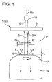
- a fastener is molded with synthetic resin integrally as an assembly of fasteners including the portion indicated by two-dot long and two short dashes lines and, this fastener 1 is composed of a filament part 2, a bar 3 provided at one extremity of the filament part 2 and a flat head 4 disposed at the other extremity of the filament part.
- fasteners 1 are formed implanted as a comb on a link rod 11 by intermediate of a linkage portion 10 indicated by two-dot long and two short dashes lines to said bar 3.
- Synthetic resins to be used include polypropylene, nylon or other molecular oriented thermoplastic resins and, they can be colored with a desired color by blending the synthetic resin with pigments before molding, according to the application of this fastener 1.
- This fastener 1 is manufactured by "intra-dice elongation method" and, after the integral molding as an assembly as shown in Fig. 1 in dice, the filament part 2 is elongated by about 3 to 5 times evenly and substantially over the total length by displacing one die in respect of the other from a parting fact PL1 orthogonal to the filament part. Then, a parting face PL2 (joining face of the upper and the lower dice) orthogonal to said parting face PL1 is opened to take out the assembly of fasteners 1 from the dice.
- the filament part 2 is smaller in diameter and stronger than the non-elongated filament part 2' indicated by two-dot long and two short dashes lines as silken gut and presents such a strength that it can no more be torn off easily by hands.
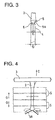
- this filament part 2 During the elongation operation of this filament part 2, a stress is to be applied to a junction portion 5 formed at the edge of the bar 3 and the head 4. Moreover, as for this filament part 2, the strength of a root portion 2A with the bar 3 and the filament part 2 is improved by said elongation operation and, the bar 3 pushed out from the hollow needle at the tip of a not shown applicator restores the original configuration by the spring stress of the filament part, namely, so that it will be directed orthogonal in T to the filament part 2. Note that the bar 3 is formed to present a diameter substantially equivalent to the diameter of the non-elongated filament part 2'.
- the head 4 is formed in flat plate form itself, with edge portions 4A of the filament part 2 side reduced to an arc form. And, between these two edge portions 4 A, A junction portion 5 narrower that the width of the head 4 is formed and, additionally, a breaking portion 6 applied in the present invention is provided in the direction transversal to this junction portion 5. (Breaking portion).
- this breaking portion 6 is formed by a pair of surface and back transversal grooves in V or in neck-form disposed in opposition the one the other on the both surface and back face of the junction portion 5.
- Said breaking portion 6 forms a part of the head 4 and, as shown in Fig. 1, even if a stress F (tensile stress) to elongate the filament part 2 is applied to this head 4, it will not break because this breaking portion is engaged with and supported by the die.
- F tensile stress
- this breaking portion 6 can easily be torn off, for example, by blocking with the tip of one hand (left hand for instance) the vicinity of the reduced junction portion 5 B which is a part of the junction portion 5 and folding the head 4 at the thin portion of the breaking portion 6 alternatively in the directions of the arrow a or b with the tip of the other hand (right for instance).
- the entire breaking portion 6 can be broken and removed by pinching the reduced junction portion 5 B of the junction portion 5 with one finger tips and twisting the head 4 in the crossing direction in respect of this junction portion 5 B, namely, as shown by the arrow R in Fig. 1.
- Said breaking portion 6 of transversal groove presenting a V-form cross-portion is spaced by a predetermined distance L (Fig. 1, even if it is a slight distance) from a front end face 5 A of the junction portion 5 as shown in Fig. 1, and when this breaking portion 6 is broken and the head 4 is separated from the filament part 2 side, this junction portion 5 will constitute a piece or thick film form reduced junction portion 5 B which is smaller by the width of said distance L and remains in T at the extremity of the filament part 2 in parallel to the bar 3.
- this thin and reduced junction portion 5 B presents such a strength that allows to bend easily into V- or U-form the narrow junction portion 5 B remaining on the filament part 2 side as shown in Fig. 4 by applying a stress (preferable equal or superior to the product binding stress) to the same 5 B.
- the filament part 2 is connected to the head by intermediate of the junction portion 5; however, as the extremity of this filament part 2 is not elongated, as shown in Fig. 1, apparently, the junction portion 5 seems to eat into the extremity 2 A of this filament part 2.
- the junction portion 5 B reduced into a thin rod or film can be folded into V- or U-form and pulled off from a part of the products S and, further, by puling off thus deformed junction portion 5 B from these products S, the fastener can be extracted.
- this breaking portion 6 can easily be torn off to remove the head 4, by pinching with the tip of one hand the filament part 2 and the junction portion 5, folding the breaking portion 6 by pinching and moving the head 4 alternatively in the directions of the arrow a and b with the tip of the other hand as shown in Fig. 2.
- the reduced junction portion 5 B can easily be removed by pinching the bar 3 remaining on the one bundle of socks S and pulling it off with the filament part 2 as indicated by the arrows C (Fig. 4) allowing to separate the socks individually.
- the thin and reduced junction portion 5 B which is a part of the junction portion 5, remaining on the filament part 2 side after the head 4 removal may be folded more easily by making thinner the center of the junction portion 5 to which the filament part 2 is connected, assuring a more effective break.
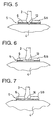
- a through hole 12 (round hole, oval hole) may be disposed at the center of the groove form breaking portion 6, namely, at the root of the filament part 2 as shown in Fig. 5, and the break may start easily form this junction portion by generating a local strain at this breaking portion 6 through this through hole 12 when a tensile stress is applied to the filament part 2.
- the cross-portion of the breaking portion 6 is not limited to the V-form transversal groove, but also, for example U- or ⁇ -form grooves may also be used.
- the portion between the filament part 2 and the head 4 may be designed to deploy a sufficient resistance to bundle products S between the filament part 2 and the head 4, but enough weak to remove the head 4 easily when a stress superior to the resistance is applied to the head 4, or a stress bending the head 4 laterally, a stress twisting the head orthogonal to the filament part 2 or to a still larger angle, or a stress dividing the head 4 is applied so that the head 4 can be removed easily by holding this head 4 and applying the stress, and moreover, a part of the junction portion 5 remaining on the filament part 2 side can be folded easily and extracted from the products without damaging the products S.
- Said breaking portion 6 of transversal groove shape is preferably formed on both sides of the junction portion 5, but it can be provided only on one face, provided that it satisfies the aforementioned conditions.
- junction portion does not break and can keep the state as formed in the elongation step of the filament part 2, but it presents a function to separate by intermediate of the breaking portion 6 when a stress folding or twisting the head 4 is applied to the filament 2; therefore, providing a junction portion 5 on the fastener piece is not different from the conventional fastener piece in no way from the functional point of view.
- Fig. 8 shows a fastener 1A according to another embodiment; in this example, a head 4A is formed in fan shape, and a junction portion 5A having a breaking portion 6A in V at the arc portion to which the filament part 2 is jointed.
- the fastener 1A of this type allows to form a long breaking portion 6A and to make the width of the junction portion 5A a narrow V form, and moreover, the elongation step can be facilitated because the stress during the filament part 2 elongation can be burdened sufficiently.
- this junction portion 5A can be separated easily from the head 1A hooking a nail to the end portion T of the junction portion 5A by facilitating its break by means of a notch provided at this end portion, or by other means.
- Fig. 9 shows a fastener 1B according to still another embodiment, wherein a half head 4B is formed, and a junction portion 5B and a breaking portion 6B are formed at the edge of this head 4B.
- this shape may presents unstable parts in the head 4B, it may also be formed by extending a part or whole of the half head 4B into the portion omitted as necessary. In this case, the length of the junction portion 5B may be conveniently formed according to the length of the head 4B.
- a fastener 1C is composed to have a semi-circular head 4C, and in this fastener 1 C, an arc from junction portion 5C and an arc form breaking portion 6C are formed.
- the head shape of the fastener according to the present invention for, otherwise, indicating the manufacturing maker, and a head among said various embodiments, or one that is deformed farther based on them may be used, and the junction portion and the breaking portion may appropriately be selected in conformity with this and applied.
Landscapes
- Physics & Mathematics (AREA)
- General Physics & Mathematics (AREA)
- Engineering & Computer Science (AREA)
- Theoretical Computer Science (AREA)
- Slide Fasteners, Snap Fasteners, And Hook Fasteners (AREA)
- Labeling Devices (AREA)
- Package Frames And Binding Bands (AREA)
Claims (5)
- Attache (1) à tête détachable (4, 4A, 4B, 4C) comprenant une partie en forme de filament allongée (2) comportant une tige (3) formée à une extrémité et la tête détachable (4, 4A, 4B, 4C) à son autre extrémité, la tige (3) formant la forme de la lettre T avec la partie en forme de filament allongée (2), caractérisée en ce que la tête (4, 4A, 4B, 4C) est formé à une partie de bord réunie à la partie en forme de filament (2) avec une partie de jonction (5, 5A, 5B, 5C) comprenant une partie sécable (6, 6A, 6B, 6C) présentant une partie localement affaiblie de telle sorte que lorsqu'une contrainte égale ou supérieure à une contrainte prédéterminée est appliquée à la tête (4, 4A, 4B, 4C), elle se brise.
- Attache à tête détachable (4, 4A, 4B, 4C) selon la revendication 1, caractérisée en ce que la partie sécable (6, 6A, 6B, 6C) est formée en réduisant l'épaisseur de la tête (4, 4A, 4B, 4C) en formant une gorge dans la direction transversale de la tête (4, 4A, 4B, 4C).
- Attache à tête détachable (4, 4A, 4B, 4C) selon la revendication 1 ou 2, caractérisée en ce que la partie sécable (6, 6A, 6B, 6C) présente une solidité qui peut résister à une force de liaison d'un produit mais qui peut être brisée par une contrainte plus forte que la force de liaison du produit, appliquée à la main sur la tête ou lorsque la tête (4, 4A, 4B, 4C)est tordue.
- Attache à tête détachable (4, 4A, 4B, 4C) selon l'une quelconque des revendications 1 à 3, caractérisée en ce que la partie sécable (6, 6A, 6B, 6C) a une forme droite ou courbe ou en V.
- Attache comportant une partie sécable (6, 6A, 6B, 6C) selon l'une quelconque des revendications 1 à 4, caractérisée en ce que la partie sécable (6, 6A, 6B, 6C) est formée avec un trou de passage (12,13) au centre de ladite partie sécable.
Applications Claiming Priority (2)
| Application Number | Priority Date | Filing Date | Title |
|---|---|---|---|
| JP10237598A JP2000066608A (ja) | 1998-08-24 | 1998-08-24 | 頭部を除去できる係止具 |
| JP23759898 | 1998-08-24 |
Publications (2)
| Publication Number | Publication Date |
|---|---|
| EP0982231A1 EP0982231A1 (fr) | 2000-03-01 |
| EP0982231B1 true EP0982231B1 (fr) | 2003-01-22 |
Family
ID=17017704
Family Applications (1)
| Application Number | Title | Priority Date | Filing Date |
|---|---|---|---|
| EP99116392A Expired - Lifetime EP0982231B1 (fr) | 1998-08-24 | 1999-08-20 | Attache à tête cassable |
Country Status (4)
| Country | Link |
|---|---|
| US (1) | US6240606B1 (fr) |
| EP (1) | EP0982231B1 (fr) |
| JP (1) | JP2000066608A (fr) |
| DE (1) | DE69904996T2 (fr) |
Families Citing this family (10)
| Publication number | Priority date | Publication date | Assignee | Title |
|---|---|---|---|---|
| CN1297445C (zh) * | 2000-11-03 | 2007-01-31 | 艾弗芮丹尼逊有限公司 | 系固件坯料 |
| US7356884B2 (en) * | 2003-12-18 | 2008-04-15 | 3M Innovative Properties Company | Fastener for a display page |
| US7414192B2 (en) * | 2004-03-22 | 2008-08-19 | Hubbell Incorporated | Temporary attachment apparatus for an accessory |
| US7654618B2 (en) * | 2005-04-08 | 2010-02-02 | Tk Holdings Inc. | Webbing tack |
| US7520030B2 (en) * | 2005-08-08 | 2009-04-21 | Thomas & Betts International, Inc. | Cable tie having detachable tail |
| US7176378B1 (en) | 2006-05-10 | 2007-02-13 | Hubbell Incorporated | Temporary attachment apparatus for an electrical box |
| CN102046475B (zh) * | 2008-05-28 | 2014-12-10 | M.I.T.国际有限公司 | 扣合片安装装置 |
| WO2018125927A1 (fr) * | 2016-12-29 | 2018-07-05 | Avery Dennison Corporation | Dispositif de fixation pour l'horticulture |
| JP7102225B2 (ja) * | 2018-05-18 | 2022-07-19 | 株式会社トスカバノック | ロック用係止ピン材のアッセンブリとロック用係止ピン材 |
| JP6896300B2 (ja) * | 2019-12-17 | 2021-06-30 | 日本成型産業株式会社 | 係止具および係止具集合体 |
Family Cites Families (8)
| Publication number | Priority date | Publication date | Assignee | Title |
|---|---|---|---|---|
| US3686717A (en) * | 1971-03-05 | 1972-08-29 | Dennison Mfg Co | Article attachment and mounting device |
| US4347932A (en) * | 1977-10-27 | 1982-09-07 | Clements Industries, Inc. | Tag pin |
| US4263730A (en) * | 1978-01-06 | 1981-04-28 | Ben Clements & Sons, Inc. | Filament-type attachment device with label and method of manufacture |
| US4263697A (en) * | 1979-06-04 | 1981-04-28 | Illinois Tool Works Inc. | Security seal |
| AU544390B2 (en) * | 1981-08-27 | 1985-05-23 | Envopak Ltd. | Disposable one-piece security sealing device |
| US5027477A (en) * | 1989-03-20 | 1991-07-02 | Seron Manufacturing Company | Break away lanyard |
| US5414903A (en) * | 1993-05-04 | 1995-05-16 | Porteous; Don D. | Single use, disposable dental bib holder system |
| US5463799A (en) * | 1993-07-08 | 1995-11-07 | R. William Graham | Fastener for connecting materials with weakened portion |
-
1998
- 1998-08-24 JP JP10237598A patent/JP2000066608A/ja active Pending
-
1999
- 1999-08-18 US US09/376,322 patent/US6240606B1/en not_active Expired - Fee Related
- 1999-08-20 DE DE69904996T patent/DE69904996T2/de not_active Expired - Fee Related
- 1999-08-20 EP EP99116392A patent/EP0982231B1/fr not_active Expired - Lifetime
Also Published As
| Publication number | Publication date |
|---|---|
| DE69904996T2 (de) | 2003-11-06 |
| EP0982231A1 (fr) | 2000-03-01 |
| JP2000066608A (ja) | 2000-03-03 |
| DE69904996D1 (de) | 2003-02-27 |
| US6240606B1 (en) | 2001-06-05 |
Similar Documents
| Publication | Publication Date | Title |
|---|---|---|
| EP0982231B1 (fr) | Attache à tête cassable | |
| US3990619A (en) | Fastener attachment needle | |
| KR100381055B1 (ko) | 쌍꺼풀 형성용 테이프 또는 실, 및 그 제조방법 | |
| US5463799A (en) | Fastener for connecting materials with weakened portion | |
| EP0945647B1 (fr) | Embout pour extrémité de cordon | |
| EP0232904B1 (fr) | Dispositif de fermeture pliable pour sacs souples | |
| US5745957A (en) | In-line cable tie | |
| CA2200474C (fr) | Dispositifs pour fixer des boutons et barrette comprenant de tels dispositifs | |
| US3733657A (en) | Assembly of attachments and method of manipulating the same | |
| EP0858419B1 (fr) | Dispositif d'attache a circonference fixe comportant une extremite libre non proeminente | |
| US4901854A (en) | Loop connected attachments | |
| AU2021210370B2 (en) | Tag anchor and method of use | |
| JPH0699954A (ja) | 結束方法および結束具 | |
| US20080196215A1 (en) | Cable tie | |
| CS218683A2 (en) | Extraktor chirurgickych svorek | |
| US10077146B2 (en) | Packaging tie | |
| US4739565A (en) | Ear tags | |
| US6318553B1 (en) | Plastic fastener and needle well-suited for use in the dispensing thereof | |
| US5261530A (en) | Carrier stock with tear-open tabs | |
| AU593067B2 (en) | Snag resistant connected paddle fastener | |
| JPH11149248A (ja) | 係止具 | |
| US4425394A (en) | Web of tags and method of attaching tags | |
| US3972469A (en) | Bag closure | |
| JP3636608B2 (ja) | 切断部付き環状連結具 | |
| JP4340352B2 (ja) | 結束バンド |
Legal Events
| Date | Code | Title | Description |
|---|---|---|---|
| PUAI | Public reference made under article 153(3) epc to a published international application that has entered the european phase |
Free format text: ORIGINAL CODE: 0009012 |
|
| AK | Designated contracting states |
Kind code of ref document: A1 Designated state(s): DE IT |
|
| AX | Request for extension of the european patent |
Free format text: AL;LT;LV;MK;RO;SI |
|
| 17P | Request for examination filed |
Effective date: 20000725 |
|
| AKX | Designation fees paid |
Free format text: DE IT |
|
| 17Q | First examination report despatched |
Effective date: 20010613 |
|
| GRAG | Despatch of communication of intention to grant |
Free format text: ORIGINAL CODE: EPIDOS AGRA |
|
| GRAG | Despatch of communication of intention to grant |
Free format text: ORIGINAL CODE: EPIDOS AGRA |
|
| GRAH | Despatch of communication of intention to grant a patent |
Free format text: ORIGINAL CODE: EPIDOS IGRA |
|
| GRAH | Despatch of communication of intention to grant a patent |
Free format text: ORIGINAL CODE: EPIDOS IGRA |
|
| GRAA | (expected) grant |
Free format text: ORIGINAL CODE: 0009210 |
|
| AK | Designated contracting states |
Kind code of ref document: B1 Designated state(s): DE IT |
|
| REF | Corresponds to: |
Ref document number: 69904996 Country of ref document: DE Date of ref document: 20030227 Kind code of ref document: P |
|
| PGFP | Annual fee paid to national office [announced via postgrant information from national office to epo] |
Ref country code: DE Payment date: 20031023 Year of fee payment: 5 |
|
| PLBE | No opposition filed within time limit |
Free format text: ORIGINAL CODE: 0009261 |
|
| STAA | Information on the status of an ep patent application or granted ep patent |
Free format text: STATUS: NO OPPOSITION FILED WITHIN TIME LIMIT |
|
| 26N | No opposition filed |
Effective date: 20031023 |
|
| PG25 | Lapsed in a contracting state [announced via postgrant information from national office to epo] |
Ref country code: DE Free format text: LAPSE BECAUSE OF NON-PAYMENT OF DUE FEES Effective date: 20050301 |
|
| PG25 | Lapsed in a contracting state [announced via postgrant information from national office to epo] |
Ref country code: IT Free format text: LAPSE BECAUSE OF NON-PAYMENT OF DUE FEES Effective date: 20050820 |