EP0982260A1 - Einrichtung zur Verminderung von Windgeräuschen an schnelllaufenden Aufzugskabinen - Google Patents
Einrichtung zur Verminderung von Windgeräuschen an schnelllaufenden Aufzugskabinen Download PDFInfo
- Publication number
- EP0982260A1 EP0982260A1 EP99115668A EP99115668A EP0982260A1 EP 0982260 A1 EP0982260 A1 EP 0982260A1 EP 99115668 A EP99115668 A EP 99115668A EP 99115668 A EP99115668 A EP 99115668A EP 0982260 A1 EP0982260 A1 EP 0982260A1
- Authority
- EP
- European Patent Office
- Prior art keywords
- attachment element
- elevator car
- add
- guide
- shaped
- Prior art date
- Legal status (The legal status is an assumption and is not a legal conclusion. Google has not performed a legal analysis and makes no representation as to the accuracy of the status listed.)
- Withdrawn
Links
- 238000007373 indentation Methods 0.000 claims description 8
- 239000000969 carrier Substances 0.000 claims description 4
- 230000007704 transition Effects 0.000 description 6
- 239000000463 material Substances 0.000 description 3
- 229920002430 Fibre-reinforced plastic Polymers 0.000 description 2
- 238000010276 construction Methods 0.000 description 2
- 238000011161 development Methods 0.000 description 2
- 230000018109 developmental process Effects 0.000 description 2
- 238000010586 diagram Methods 0.000 description 2
- 230000000694 effects Effects 0.000 description 2
- 239000011151 fibre-reinforced plastic Substances 0.000 description 2
- 239000006260 foam Substances 0.000 description 2
- 239000011358 absorbing material Substances 0.000 description 1
- 238000005452 bending Methods 0.000 description 1
- 230000015572 biosynthetic process Effects 0.000 description 1
- 230000037237 body shape Effects 0.000 description 1
- 238000004364 calculation method Methods 0.000 description 1
- 230000015556 catabolic process Effects 0.000 description 1
- 238000006073 displacement reaction Methods 0.000 description 1
- 230000008030 elimination Effects 0.000 description 1
- 238000003379 elimination reaction Methods 0.000 description 1
- 238000012423 maintenance Methods 0.000 description 1
- 238000005259 measurement Methods 0.000 description 1
- 239000002184 metal Substances 0.000 description 1
- 238000000034 method Methods 0.000 description 1
- 239000013518 molded foam Substances 0.000 description 1
- 239000004033 plastic Substances 0.000 description 1
- 229920003023 plastic Polymers 0.000 description 1
- 239000000725 suspension Substances 0.000 description 1
- 238000013519 translation Methods 0.000 description 1
Images


Classifications
-
- B—PERFORMING OPERATIONS; TRANSPORTING
- B66—HOISTING; LIFTING; HAULING
- B66B—ELEVATORS; ESCALATORS OR MOVING WALKWAYS
- B66B11/00—Main component parts of lifts in, or associated with, buildings or other structures
- B66B11/02—Cages, i.e. cars
- B66B11/0226—Constructional features, e.g. walls assembly, decorative panels, comfort equipment, thermal or sound insulation
Definitions
- the present invention relates to a device for Reduction of wind noise and vibrations high-speed elevator cars, consisting of at least one aerodynamic element built on the cabin and one Access to the cabin roof.
- Wind noise and vibrations arise from air swirls on and around the outer contours of an elevator car when driving with large ones Speeds from about 4m / sec.
- Air whirls should have a body shape in the elevator car which drives the air displaced while driving as free of swirls as possible can flow.
- Such a form can in principle be vertical protruding physical structures can be achieved, which on the arranged upper and lower end of an elevator car become.
- US 5,220,979 discloses a number of solutions for up and down Attachments to elevator cars with the aim of accelerating air flow suppress in the entrance area.
- the common Characteristic of all proposed solutions is that each on the entrance side at the elevator car above and below at least one additional one to the front of the shaft wall parallel surface is created.
- pent roof-like structures with side panels (Fig. 3A / B, 4A / B / C, 9) proposed below and above the elevator car.
- Further Solutions concern air-permeable apron elements (Fig. 5-8).
- 10 and 11A show development steps according to the solution Fig. 11B, the latter largely that previously mentioned Representation in the Elevator World corresponds.
- Three of the four pages which are the upper and lower attached hollow body curved in one direction only. The transitions from one side to the other next page are edgy.
- GB 2 280 662 discloses similar but very high opening and closing Add-ons with simply curved surfaces with angular transitions and plan with the front wall of the shaft parallel surfaces. As a special feature, doors are provided for opening on the latter for access to the top and bottom of the cabin. The large construction height of the superstructures necessitates larger crossings at the Shaft ends.
- the device according to the invention is characterized in that a first, for example ellipsoidal attachment as attachable hood with curved outer surfaces and spherical shaped transitions for the top of the elevator car is provided.
- a second, aerodynamically shaped attachment as frame-shaped hollow body with rounded outer and inner surfaces be attached to the underside of the elevator car.
- the upper attachment is with a manual and / or motor operable lifting device provided by means of which on the one hand access for maintenance work on the top of the cabin is made possible and on the other hand the possibility of escape for any trapped passengers is guaranteed.
- the lifting device consists of one of the open Emergency exit hatch or from the elevator shaft through a For example, opening, operable winch and a lifting rope, which is at the top of the upper attachment is attached, from there via a pulley above the top Add-on element and a deflection roller within the add-on element leads to the winch.
- the Motor powered by an auxiliary power source in the event of a power failure.
- the upper add-on element is fastened via a Centering device on the top of the cabin put on and only with its own weight in the set position kept reliable.
- the elimination of any mounting fittings facilitates its rapid removal by immediate lifting in the Emergency.
- the centering device consists of an am on the element side Element edge, for example riveted, centering with Profile edge and cabin side from a centering frame with same second profile edge matching the first profile edge.
- both profile edges form a secure one Positive connection between the attached element and the Elevator car, with an elastic liner between the Profile edges have a noise and vibration dampening effect.
- the attachable upper attachment element also has a guide side a channel-shaped indentation, which is spaced on all sides surround the guide roller carrier.
- the course of the flow is the inner surface of the indentations Vertical slightly slanted towards the cabin center and the Transitions to the side surfaces gently rounded.
- At least one detachable separating seam enables the upper one to be installed Extension element in at least two halves. Is only a dividing seam provided, it is preferably at right angles to Management level provided.
- the lower attachment element is a frame-shaped hollow body trained and is by means of a profiled mounting edge attached to the bottom of the cabin.
- Channels molded on both sides enclose the lower ones Guide roller carrier to avoid air turbulence at high Driving speed. They serve the same purpose subsequent, somewhat cantilevered paneling for the Guide rails.
- the underside of the lower attachment element is curved Inside of the frame and two hinged lids to open. These hinged lids provide access to the electrical and mechanical fittings underneath the cabin guaranteed. Simple, manually operated closures hold the Lid in the closed position.
- the attachments above and below are lightweight, preferably made of fiber-reinforced plastic and have if necessary reinforced with ribs on the inside, a high one Dimensional stability so that even at high speeds no vibrations of the element walls occur.
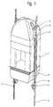
- FIG. 1 shows an elevator car 1 with the one according to the invention Device shown, which is essentially one on the Upper add-on element 3 placed on top of elevator car 1 and a lower one attached to the underside of the elevator car 1 Attachment 4 has.
- the elevator car 1 runs by means of the lower one and upper guide rollers 5 and 7 on guides 2.
- Die Guide rollers 5 and 7 are on guide roller carriers 6 and 8 vertically spaced from the prismatic cabin body and protrude vertically beyond the add-on elements 3 and 4.
- Existing cabin ropes, lower ropes and hanging cables are closed In favor of a clear representation of the add-on elements 3 and 4 omitted in this Fig.1.
- Cantilevered parts and Indentations of the add-on elements 3 and 4 partially enclose the Guide roller carriers 6 and 8 and the guide rails 2.
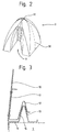
- FIG. 2 shows the upper add-on element 3 from the guide side seen with a channel-shaped indentation 9.
- the thereby created free space around the guide roller carrier 6 largely enables one at high driving speeds free air flow in this zone.
- the three inner ones Flanks of the side recess 9 shaped so that the Indentation 9 extends somewhat vertically upwards.
- An opening 31 on the top of the upper attachment 3 is used for implementation of suspension cables for the elevator car 1.
- a detachable separating seam 30 provided which, for example, at right angles to Management level runs.
- FIG. 3 shows in cross section the formation of the lower edge zone the upper attachment 3 and the details of its connection with the elevator car 1.
- the lower edge zone is at the Element wall 10 on the circumference of the upper add-on element 3 stiffening, multi-angled centering plate 11 attached, which is horizontal in a gable roof-shaped profile edge 12 ends.
- the top of the elevator car 1 is off a frame-shaped centering attachment 14 Mistake.
- the bending profile of the centering attachment 14 has one profile roof-shaped profile edge 15, which fits exactly the same Has shape like the profile edge 12 of the centering plate 11.
- With 13 is an elastic intermediate layer called, for example is glued to the profile edge 15 of the centering frame 14.
- the elastic intermediate layer 13 serves to dampen noise and Vibrations. From Figure 3 it can be seen that the on Centering frame 14 attached top attachment 3 form-fitting is held against lateral displacement and by No additional weight even in the vertical direction Attachment required. By simply lifting the add-on element 3 the top of the elevator car becomes accessible.
- Fig. 4 shows the plastic ellipsoid-like shape of the upper attachment element 3.
- rounded transitions from side to side and to the Indentations 9 can be seen. These gently rounded transitions only result in one between the different surface zones airflow flowing around when driving fast.
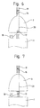
- FIG. 6 and 7 show two variants of a principle representation Lifting device for lifting the top attachment 3 for the purpose Accessibility of the top of the cabin and any evacuation trapped passengers in the event of a breakdown.
- a manually operated winch 18 is placed, which from the open, not shown emergency exit hatch or by one mentioned at the beginning, also not shown hinged opening can be operated from the shaft.
- the Cable winch 18 guides a hoisting rope 20 around a deflection roller 17 onto one deflection roller 16 fastened to the support cables 19 by means of a cable clamp to the top of the upper attachment element 3, where it is attached.
- the difference between the two variants is not more fundamental Nature, but only refers to the arrangement of the deflection roller 17. According to FIG.
- the deflection roller 17 is on the upper attachment element 3 itself attached and according to Figure 7, the deflecting roller 17 via a Rope clamp attached to the support cables 19.
- a adapted translation of the winch 18 is the effort for lifting the upper add-on element 3 so low that the Lifting device from an average strong person without great effort can be served.
- FIG. 8 shows a three-dimensional view of the lower one Attachment 4 seen obliquely from above, which as frame-shaped hollow body is formed.
- At 23 is one profiled mounting edge, over which the lower Add-on element firmly connected to the underside of the elevator car 1 becomes.
- the lower attachment element 4 has on the input side of the Elevator car on a flat surface 22, which as regulation apron.
- the two side and the rear outer surfaces 21 are rounded inwards downwards.
- Channels 24 molded on the inside enclose the lower ones Guide roller carrier 8 completely and cantilevered Guide covers partially surround the guides 2.
- FIG. 9 shows a three-dimensional view of the lower one Add-on element 4 seen obliquely from below.
- Domed Inner sides of the frame 26 enclose a rectangular surface which is closed by means of two lids 27.
- the hinges 29 hinged lid 27 can be opened downwards become and allow access to the electrical and mechanical fittings on the underside of the cabin. Simple not Locks shown hold the lid 27 during Elevator operation reliably in the closed position.
- a Through opening 28 on the front edges of the lid 27 is used Implementation of the lower ropes and the hanging cables.
- the Through opening 28 is preferably with foam inserts sealed against air flowing in while driving.
- Figure 10 shows a side view of the true form of the inward rounded side surfaces 21 and the flat front surface 22 of the Outside of the lower add-on element 4.
- the outer shapes of the add-on elements 3 and 4 were made in addition to the Use of relevant calculation methods including Determined using various noise and vibration measurements and show the best in this regard with the forms shown Results. However, that does not exclude that the shown Outer forms specific to the system in individual surface zones of may differ from the illustrated form examples.
- any Systems such as hydraulic, compressed air, spindle, Chain or gripping systems can be provided.
Landscapes
- Engineering & Computer Science (AREA)
- Civil Engineering (AREA)
- Mechanical Engineering (AREA)
- Structural Engineering (AREA)
- Cage And Drive Apparatuses For Elevators (AREA)
Abstract
Description
Claims (10)
- Einrichtung zur Verminderung von Windgeräuschen und Vibrationen an schnelllaufenden Aufzugskabinen (1), bestehend aus mindestens einem auf die Kabine aufgebauten aerodynamischen Element (3, 4) und einer Zugangsmöglichkeit auf das Kabinendach,
dadurch gekennzeichnet,
dass die Einrichtung ein ellipsoidähnliches oberes Anbauelement (3), vorzugsweise ein rahmenförmiges unteres Anbauelement (4) und eine Hebevorrichtung für das obere Anbauelement (3) aufweist. - Einrichtung nach Anspruch 1,
dadurch gekennzeichnet,
dass das obere Anbauelement (3) am unteren Rand und die Aufzugskabine (1) an ihrer Oberseite formschlüssig zusammenpassende Zentriereinrichtungen (11-15) aufweisen. - Einrichtung nach Anspruch 1
dadurch gekennzeichnet,
dass das obere Anbauelement (3) lose auf das Kabinendach aufgesetzt ist. - Einrichtung nach Anspruch 1,
dadurch gekennzeichnet,
dass die Hebevorrichtung im wesentlichen eine Seilwinde (18) mit Seil (20), Ablenk- und Umlenkrollen (17, 16) aufweist. - Einrichtung nach Anspruch 4,
dadurch gekennzeichnet, dass die Hebevorrichtung manuell und/oder motorisch betreibbar ausgeführt ist. - Einrichtung nach Anspruch 1,
dadurch gekennzeichnet,
dass das obere Anbauelement (3) mindestens eine lösbare Trennnaht (30) aufweist. - Einrichtung nach Anspruch 1,
dadurch gekennzeichnet,
dass das obere Anbauelement (3) führungsseitig kanalförmige Einbuchtungen (9) aufweist, welche die Führungsrollenträger (6) und die Führungsschienen (2) umschliessen. - Einrichtung nach Anspruch 1,
dadurch gekennzeichnet,
dass das untere Anbauelement (4) als rahmenförmiger Hohlkörper ausgebildet ist. - Einrichtung nach Anspruch 8,
dadurch gekennzeichnet,
dass das untere Anbauelement (4) mittels abklappbaren Deckeln (27) verschlossen ist, die den Zugang zu den mechanischen und elektrischen Armaturen an der Unterseite der Aufzugskabine (1) ermöglichen. - Einrichtung nach Anspruch 7,
dadurch gekennzeichnet,
dass das untere Anbauelement (4) eingeformte Kanäle (24) für die unteren Führungsrollenträger (8) und auskragende Führungsverkleidungen (25) für die teilweise Umschliessung der Führungsschienen (2) aufweist.
Priority Applications (1)
| Application Number | Priority Date | Filing Date | Title |
|---|---|---|---|
| EP99115668A EP0982260A1 (de) | 1998-08-17 | 1999-08-09 | Einrichtung zur Verminderung von Windgeräuschen an schnelllaufenden Aufzugskabinen |
Applications Claiming Priority (3)
| Application Number | Priority Date | Filing Date | Title |
|---|---|---|---|
| EP98810787 | 1998-08-17 | ||
| EP98810787 | 1998-08-17 | ||
| EP99115668A EP0982260A1 (de) | 1998-08-17 | 1999-08-09 | Einrichtung zur Verminderung von Windgeräuschen an schnelllaufenden Aufzugskabinen |
Publications (1)
| Publication Number | Publication Date |
|---|---|
| EP0982260A1 true EP0982260A1 (de) | 2000-03-01 |
Family
ID=26151990
Family Applications (1)
| Application Number | Title | Priority Date | Filing Date |
|---|---|---|---|
| EP99115668A Withdrawn EP0982260A1 (de) | 1998-08-17 | 1999-08-09 | Einrichtung zur Verminderung von Windgeräuschen an schnelllaufenden Aufzugskabinen |
Country Status (1)
| Country | Link |
|---|---|
| EP (1) | EP0982260A1 (de) |
Cited By (3)
| Publication number | Priority date | Publication date | Assignee | Title |
|---|---|---|---|---|
| EP1262438A1 (de) * | 2001-06-01 | 2002-12-04 | Thyssen Aufzugswerke GmbH | Fahrkorb für einen Aufzug |
| US6615952B2 (en) * | 2000-03-02 | 2003-09-09 | Kabushiki Kaisha Toshiba | Double deck elevator |
| CN105270966A (zh) * | 2014-07-17 | 2016-01-27 | 株式会社日立制作所 | 电梯装置 |
Citations (3)
| Publication number | Priority date | Publication date | Assignee | Title |
|---|---|---|---|---|
| JPH03293281A (ja) * | 1990-04-11 | 1991-12-24 | Mitsubishi Electric Corp | エレベータかごの外装装置 |
| JPH06298473A (ja) * | 1993-04-20 | 1994-10-25 | Mitsubishi Electric Corp | エレベーターの整風カバー装置 |
| JPH09110344A (ja) * | 1995-10-24 | 1997-04-28 | Hitachi Ltd | エレベータかごの整風装置 |
-
1999
- 1999-08-09 EP EP99115668A patent/EP0982260A1/de not_active Withdrawn
Patent Citations (3)
| Publication number | Priority date | Publication date | Assignee | Title |
|---|---|---|---|---|
| JPH03293281A (ja) * | 1990-04-11 | 1991-12-24 | Mitsubishi Electric Corp | エレベータかごの外装装置 |
| JPH06298473A (ja) * | 1993-04-20 | 1994-10-25 | Mitsubishi Electric Corp | エレベーターの整風カバー装置 |
| JPH09110344A (ja) * | 1995-10-24 | 1997-04-28 | Hitachi Ltd | エレベータかごの整風装置 |
Non-Patent Citations (3)
| Title |
|---|
| PATENT ABSTRACTS OF JAPAN vol. 016, no. 132 (M - 1229) 3 April 1992 (1992-04-03) * |
| PATENT ABSTRACTS OF JAPAN vol. 095, no. 001 28 February 1995 (1995-02-28) * |
| PATENT ABSTRACTS OF JAPAN vol. 097, no. 008 29 August 1997 (1997-08-29) * |
Cited By (8)
| Publication number | Priority date | Publication date | Assignee | Title |
|---|---|---|---|---|
| US6615952B2 (en) * | 2000-03-02 | 2003-09-09 | Kabushiki Kaisha Toshiba | Double deck elevator |
| EP1129978A3 (de) * | 2000-03-02 | 2004-02-04 | Kabushiki Kaisha Toshiba | Doppeldeckeraufzug |
| KR100435242B1 (ko) * | 2000-03-02 | 2004-06-11 | 가부시끼가이샤 도시바 | 더블 데크 엘리베이터 |
| US7077240B2 (en) | 2000-03-02 | 2006-07-18 | Kabushiki Kaisha Toshiba | Covers between an upper cage and a lower cage of a double deck elevator |
| US7287624B2 (en) | 2000-03-02 | 2007-10-30 | Kabushiki Kaisha Toshiba | Double deck elevator |
| EP1262438A1 (de) * | 2001-06-01 | 2002-12-04 | Thyssen Aufzugswerke GmbH | Fahrkorb für einen Aufzug |
| EP1262438B2 (de) † | 2001-06-01 | 2014-04-16 | ThyssenKrupp Elevator AG | Fahrkorb für einen Aufzug |
| CN105270966A (zh) * | 2014-07-17 | 2016-01-27 | 株式会社日立制作所 | 电梯装置 |
Similar Documents
| Publication | Publication Date | Title |
|---|---|---|
| DE69418496T2 (de) | Antriebsscheibenaufzug | |
| DE69400467T2 (de) | Antriebsscheibenaufzug mit unter befindlicher Antriebsmaschine | |
| WO2011138178A1 (de) | Aufzugskabine und verfahren zum betreiben einer aufszugsanlage mit einer aufzugskabine | |
| EP1056678A2 (de) | Vormontierter aufzugsschacht | |
| EP2516314B1 (de) | Aufzugskabine | |
| EP1489033B1 (de) | Aufzugsanlage mit in einem Schacht übereinander angeordneten Kabinen | |
| DE69018247T2 (de) | Reduzierung von Geräusch und Schwingungen in einer Aufzugskabine durch selektive Verringerungen der Durchwirbelung der Luft. | |
| EP1035066A1 (de) | Flexible Aufzugkabinenhaube zur Verminderung von Strömungsgeräuschen | |
| DE69204216T2 (de) | Schürze für einen Aufzug. | |
| EP0982260A1 (de) | Einrichtung zur Verminderung von Windgeräuschen an schnelllaufenden Aufzugskabinen | |
| DE102004046146A1 (de) | Flugzeug mit einer Lifteinrichtung | |
| EP2014598A1 (de) | Antrieb für Vertikalaufzüge | |
| DE69714465T2 (de) | Omnibus mit sicherheitsvorrichtungen wie eine überrollvorrichtung, sowie verfahren zum zusammenbau eines omnibuses | |
| DE2458951C3 (de) | Aufzug | |
| DE102006044669A1 (de) | Maschinenraumloser Treibkörperaufzug | |
| EP1215157A1 (de) | Anordnung des Aufzugantriebes | |
| AT524942B1 (de) | Seilbahnfahrzeug | |
| EP1656318B9 (de) | Verfahren zur Montage eines Aufzugs | |
| WO2018215392A1 (de) | FAHRKORB FÜR EINE AUFZUGSANLAGE UND VERFAHREN ZUM ÖFFNEN UND SCHLIEßEN EINER TÜRÖFFNUNG | |
| EP0834441B1 (de) | Fahrzeugkarosserie mit einem einen Deckel aufweisenden Anbau | |
| DE3921381A1 (de) | Kraftfahrzeug | |
| AT410784B (de) | Aufzug | |
| DE20320004U1 (de) | Treibscheibenaufzug in Rucksackbauweise | |
| DE202022106608U1 (de) | Fahrkorb für eine Aufzugsanlage, aufweisend eine Steuereinheit | |
| DE29824824U1 (de) | Seil-Aufzug mit Treibscheibe |
Legal Events
| Date | Code | Title | Description |
|---|---|---|---|
| PUAI | Public reference made under article 153(3) epc to a published international application that has entered the european phase |
Free format text: ORIGINAL CODE: 0009012 |
|
| AK | Designated contracting states |
Kind code of ref document: A1 Designated state(s): AT BE CH CY DE DK ES FI FR GB GR IE IT LI LU MC NL PT SE |
|
| AX | Request for extension of the european patent |
Free format text: AL;LT;LV;MK;RO;SI |
|
| 17P | Request for examination filed |
Effective date: 20000816 |
|
| AKX | Designation fees paid |
Free format text: AT BE CH CY DE DK ES FI FR GB GR IE IT LI LU MC NL PT SE |
|
| GRAH | Despatch of communication of intention to grant a patent |
Free format text: ORIGINAL CODE: EPIDOS IGRA |
|
| STAA | Information on the status of an ep patent application or granted ep patent |
Free format text: STATUS: THE APPLICATION IS DEEMED TO BE WITHDRAWN |
|
| 18D | Application deemed to be withdrawn |
Effective date: 20030301 |
|
| REG | Reference to a national code |
Ref country code: HK Ref legal event code: WD Ref document number: 1026681 Country of ref document: HK |