EP0982433A2 - Siebkorb für einen Drucksortierer mit einem entfern- und ersetzbaren zylindrischen Sieb - Google Patents
Siebkorb für einen Drucksortierer mit einem entfern- und ersetzbaren zylindrischen Sieb Download PDFInfo
- Publication number
- EP0982433A2 EP0982433A2 EP99115643A EP99115643A EP0982433A2 EP 0982433 A2 EP0982433 A2 EP 0982433A2 EP 99115643 A EP99115643 A EP 99115643A EP 99115643 A EP99115643 A EP 99115643A EP 0982433 A2 EP0982433 A2 EP 0982433A2
- Authority
- EP
- European Patent Office
- Prior art keywords
- support ring
- filter element
- basket according
- sieve basket
- cylindrical
- Prior art date
- Legal status (The legal status is an assumption and is not a legal conclusion. Google has not performed a legal analysis and makes no representation as to the accuracy of the status listed.)
- Granted
Links
Images


Classifications
-
- B—PERFORMING OPERATIONS; TRANSPORTING
- B01—PHYSICAL OR CHEMICAL PROCESSES OR APPARATUS IN GENERAL
- B01D—SEPARATION
- B01D29/00—Filters with filtering elements stationary during filtration, e.g. pressure or suction filters, not covered by groups B01D24/00 - B01D27/00; Filtering elements therefor
- B01D29/11—Filters with filtering elements stationary during filtration, e.g. pressure or suction filters, not covered by groups B01D24/00 - B01D27/00; Filtering elements therefor with bag, cage, hose, tube, sleeve or like filtering elements
- B01D29/111—Making filtering elements
-
- B—PERFORMING OPERATIONS; TRANSPORTING
- B01—PHYSICAL OR CHEMICAL PROCESSES OR APPARATUS IN GENERAL
- B01D—SEPARATION
- B01D29/00—Filters with filtering elements stationary during filtration, e.g. pressure or suction filters, not covered by groups B01D24/00 - B01D27/00; Filtering elements therefor
- B01D29/11—Filters with filtering elements stationary during filtration, e.g. pressure or suction filters, not covered by groups B01D24/00 - B01D27/00; Filtering elements therefor with bag, cage, hose, tube, sleeve or like filtering elements
- B01D29/13—Supported filter elements
- B01D29/23—Supported filter elements arranged for outward flow filtration
-
- B—PERFORMING OPERATIONS; TRANSPORTING
- B01—PHYSICAL OR CHEMICAL PROCESSES OR APPARATUS IN GENERAL
- B01D—SEPARATION
- B01D29/00—Filters with filtering elements stationary during filtration, e.g. pressure or suction filters, not covered by groups B01D24/00 - B01D27/00; Filtering elements therefor
- B01D29/50—Filters with filtering elements stationary during filtration, e.g. pressure or suction filters, not covered by groups B01D24/00 - B01D27/00; Filtering elements therefor with multiple filtering elements, characterised by their mutual disposition
- B01D29/52—Filters with filtering elements stationary during filtration, e.g. pressure or suction filters, not covered by groups B01D24/00 - B01D27/00; Filtering elements therefor with multiple filtering elements, characterised by their mutual disposition in parallel connection
- B01D29/54—Filters with filtering elements stationary during filtration, e.g. pressure or suction filters, not covered by groups B01D24/00 - B01D27/00; Filtering elements therefor with multiple filtering elements, characterised by their mutual disposition in parallel connection arranged concentrically or coaxially
-
- B—PERFORMING OPERATIONS; TRANSPORTING
- B01—PHYSICAL OR CHEMICAL PROCESSES OR APPARATUS IN GENERAL
- B01D—SEPARATION
- B01D29/00—Filters with filtering elements stationary during filtration, e.g. pressure or suction filters, not covered by groups B01D24/00 - B01D27/00; Filtering elements therefor
- B01D29/96—Filters with filtering elements stationary during filtration, e.g. pressure or suction filters, not covered by groups B01D24/00 - B01D27/00; Filtering elements therefor in which the filtering elements are moved between filtering operations; Particular measures for removing or replacing the filtering elements; Transport systems for filters
-
- D—TEXTILES; PAPER
- D21—PAPER-MAKING; PRODUCTION OF CELLULOSE
- D21D—TREATMENT OF THE MATERIALS BEFORE PASSING TO THE PAPER-MAKING MACHINE
- D21D5/00—Purification of the pulp suspension by mechanical means; Apparatus therefor
- D21D5/02—Straining or screening the pulp
- D21D5/16—Cylinders and plates for screens
-
- Y—GENERAL TAGGING OF NEW TECHNOLOGICAL DEVELOPMENTS; GENERAL TAGGING OF CROSS-SECTIONAL TECHNOLOGIES SPANNING OVER SEVERAL SECTIONS OF THE IPC; TECHNICAL SUBJECTS COVERED BY FORMER USPC CROSS-REFERENCE ART COLLECTIONS [XRACs] AND DIGESTS
- Y10—TECHNICAL SUBJECTS COVERED BY FORMER USPC
- Y10S—TECHNICAL SUBJECTS COVERED BY FORMER USPC CROSS-REFERENCE ART COLLECTIONS [XRACs] AND DIGESTS
- Y10S29/00—Metal working
- Y10S29/902—Filter making
-
- Y—GENERAL TAGGING OF NEW TECHNOLOGICAL DEVELOPMENTS; GENERAL TAGGING OF CROSS-SECTIONAL TECHNOLOGIES SPANNING OVER SEVERAL SECTIONS OF THE IPC; TECHNICAL SUBJECTS COVERED BY FORMER USPC CROSS-REFERENCE ART COLLECTIONS [XRACs] AND DIGESTS
- Y10—TECHNICAL SUBJECTS COVERED BY FORMER USPC
- Y10T—TECHNICAL SUBJECTS COVERED BY FORMER US CLASSIFICATION
- Y10T29/00—Metal working
- Y10T29/49—Method of mechanical manufacture
- Y10T29/496—Multiperforated metal article making
Definitions
- the invention relates to a screen basket for filtering solids and contained liquids, especially for the removal of impurities aqueous fiber suspensions.
- Screening systems that use screen baskets of this type are used in manufacturing processes Often used to remove larger particles from a liquid / solid suspension to be eliminated.
- Applications for screening systems include processing, for example of pulp, mechanical wood pulp, bleached or unbleached kraft pulp, Corrugated cardboard, mixed newsprint, deinking, waste paper or any other kind of fibers.
- the system usually takes several cubic meters of liquid or solid Fiber suspension per minute and divides the larger particles by one with one Sieve basket provided pressure sorter, which usually causes a flow of waste (the smaller particles) and a flow of rejects (the larger particles). in the The fibers are concentrated and the non-fibers in the rejects Impurities. This filtering process is called sorting.
- An example for a pressure sorter is the model 400, which is available from Voith Sulzer, the Applicant of the present invention.
- Pressure sorters often filter the liquid or solid suspension through a slotted one or perforated cylindrical screen basket.
- the known designs of the screen baskets are relatively expensive and if the filter element of the screen basket breaks, the Pressure sorters can be turned off. The screen basket is then replaced and the Pressure sorter put back into operation. The defective screen basket is generally thrown away because repairs would be too difficult.
- the object of the present invention is to offer a screen basket, the Filter element is easily replaceable.
- the strainer basket contains a cylindrical, perforated filter element, surrounding and attached anchoring bands attached to the opposite sides of the filter element, at least two support rings that surround the filter element and devices to the Support rings between axially contracted positions, released from the Anchoring bands and axially extended positions, with attached Adapt the anchoring straps and axially tension the filter element.
- the subclaims indicate favorable embodiments of the invention.
- the anchor straps When they are used for the first time, the anchor straps are relatively flexible. This allows the anchor straps to be inserted of the cylindrical, perforated filter element deformed within the support rings become.
- top and bottom support rings are divided into segments that are light disassembled and reassembled to remove the defective, cylindrical, perforated filter element and the installation of a new one To facilitate filter element.
- the screen basket has a reusable, rigid frame that can be easily connected to an exchangeable perforated filter element.
- FIG. 1 shows a sieve basket 10 for filtering aqueous fiber suspensions
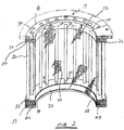
- FIG. 2 shows a cross-sectional view of the strainer basket 10 (In this view, several parts became the basket for easier illustration added, which are not shown in Fig. 1).
- the strainer basket 10 includes the strainer basket 10 is a removable and replaceable, cylindrical, perforated Filter element 12, which has an inner feed side 14 and an outer accept side 16
- the strainer basket 10 also has a rigid frame 17 which has an upper support ring 18, a lower support ring 20 and a plurality of support rods 22, which are extend between the upper and lower support rings 18, 20. It is significant that the reusable, rigid frame 17 with the removable and replaceable, cylindrical, perforated filter element 12 cooperates, which is essential Feature of the strainer basket 10 of the present invention.
- the upper support ring 18 includes an upper circular anchoring groove 24 and a plurality of upper threaded openings 26 distributed around the circumference.
- the lower support ring 20 includes a lower circular one Anchoring groove 27 (Fig. 2) and a plurality of distributed around the circumference, lower threaded openings 30, each after a corresponding opposite upper threaded opening 26 is aligned.
- the strainer basket could also include a mounting flange 31 to hold the strainer basket in the strainer basket could also include a mounting flange 31 to hold the strainer basket in to be attached to a pressure sorter (not shown).
- the mounting flange could be on the lower or upper support rings or it could be on both Support rings 18, 20 flanges can be attached: Fig.
- bracket 33 is attached over the outer axial side of the lower support ring 20 to thereby help to keep the filter element 12 in the anchoring groove 27.
- a bracket is shown mounted only in conjunction with the lower support ring
- Teen with ordinary skills will realize that just like a bracket can be mounted on the axial outside of the upper support ring 18.
- FIG. 3A shows a cross-sectional illustration through line 3-3, as shown in FIG. 1 is shown.
- the cylindrical screen 12 has a U-shaped Band that serves as the upper anchor 36 and that with the upper circular Anchoring groove 24 can be connected as well as a similarly shaped lower Anchoring connected to the lower circular anchoring groove 27 can be.
- a cylindrical net 42 is secured between the top and the lower anchor 36, 38 attached. Looking at this is the cylindrical, perforated filter element 12 with the upper and lower support ring 18, 20 of Frame 17 connected.
- the size and shape of the perforation of the cylindrical mesh will according to the minimum particle size removed from the aqueous fiber suspension should be chosen.
- each of the plurality of support rods 22, which are between extend the support rings 18, 20, have opposite threads 31, 32 at the ends, which in turn are connected to the upper and lower threaded openings 26, 30.
- the support rods 22 When the support rods 22 are rotated in one direction, the distance increases between the support rings 18, 20 because of the opposite thread 31, 32 of the Handrails 22 from. The rotation of the bars in the opposite direction increases the distance between the support rings 18, 20.
- Each of the support rods includes a screw head 33 which simplifies the turning of the rods.
- Fig. 3B shows a cross-sectional view that that of Fig. 3A, except that the Support rods 22 were rotated to detach the filter element 12 from the frame 17, is similar. While the rods 22 are rotated to loosen the filter element 12 the distance between the upper and lower support rings 18, 20 is reduced because each rod has ends with opposite threads 31, 32
- the upper and lower anchorages 36, 38 flexible. This allows the anchors 36, 38 to be compressed can, so that the cylindrical, perforated filter element 12 in the rigid frame 17 can be used.
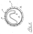
- 4 shows the cylindrical, perforated filter element 12 from above, compressed to be inserted into the frame 17.
- upper and lower anchors 36, 38 and cylindrical net 42 (not shown) are folded so that the cylindrical, meshed filter element 12 in Frame can be attached.
- the cylindrical filter element 12 is used that the upper anchor 36 is perpendicular to the axis over the upper circular Anchoring groove 24 and the lower anchoring 38 are perpendicular to the axis via the lower circular anchor groove 40 extends as shown in FIG. 3B.
- the cylindrical filter element 12 is then deployed to give it its cylindrical shape gets back.
- the rotatable support rods 22 are then rotated so that the distance what increases between the upper support ring 18 and the lower support ring 20 leads the anchors 36, 38 in their corresponding anchoring grooves 24, 27 can be fixed. This will also become the network 42 of the cylindrical filter element 12 clamp in the axial direction.
- the Handrails 22 rotated in the opposite direction to the distance between the Support rings 18, 20 to reduce. When the distance narrows, they loosen Anchors 36, 38 from their corresponding anchoring grooves 24, 27. The upper one and the lower anchor 36, 38 are then compressed as shown in FIG. 4 is shown and the cylindrical mesh filter element 12 is removed from the inside of the Frame 17 removed.
- the advantage is that in the event of a defect in the strainer basket 10 (for example a crack in the network 42) the pressure sorter is switched off and opened. The strainer basket 10 is then removed and replaced with another strainer. The pressure sorter will then closed and put back into operation. The strainer basket 10 is repaired by the defective, cylindrical, perforated filter element 12 is removed and replaced by a new cylindrical perforated filter element replaced.
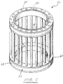
- FIG. 5 shows a perspective Representation of the strainer frame 50, which is for use with a cylindrical Mesh filter element with rigid upper and lower anchoring 36, 38 is suitable. It is important that the screen basket frame 50 contains upper and lower support rings 52, 54, which can be divided into several segments.
- the upper support ring 52 includes semicircular segments 56, 58 and the lower support ring 54 semicircular segments 60, 62.
- the lower semicircular segments 60, 62 attached around the filter element and connected along lines 64, 66 to lower circular support ring 54 to build.
- a hose clamp can be added to the to reinforce joined support rings.
- each of the many support rods 22 will be in their Threaded opening used in the lower support ring 54.
- Each of the rods 22 will preferably rotated once or twice to connect them to the threaded opening.
- the upper support ring 52 is then assembled by making the upper semicircular Interlocked segments 56, 58.
- the upper support ring 52 is then so arranged that the upper threaded openings are aligned with the rods.
- Each the rod 22 is then rotated to both the top and bottom To connect threaded openings. It is intended that the places where the semicircular segments of the upper and lower support ring are connected, are annularly offset by 90 °, as shown in Fig. 5.
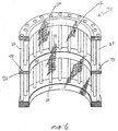
- FIG. 6 is a cross-sectional illustration of an alternative application variant, the Strainer basket 70.
- This strainer basket is essentially the same filter strainer basket as in FIG. 1 is shown, except that this basket has a central support ring 72.
- the middle support ring 72 contains a plurality of distributed around the circumference central openings 74, each one of the upper threaded openings 26 and is associated with one of the lower threaded openings 30 so that each of the support rods 22 passes through a corresponding assigned one of the central openings 74.
- the middle support ring 72 includes a wall covering 76 on which a part of the cylindrical perforated sieve is attached (for example by welding or Brazing).
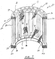
- FIG. 7 shows a cross-sectional illustration of the strainer basket 80, which has a filter element 82 with staggered rods 84 which here and there in the network 86th are incorporated (for example, by brazing them to them). It is important that the rods 84 help in cooperation with the rotor of the Pressure sorter (not shown) a turbulent flow within the strainer to create. Because the rotor rotates within the filter element 82, they work Wings of the rotor especially with the rods 84 together to create turbulence generate that helps remove the fibers from the web 86.
- the rods are 84 preferably several inches long.
- the rods 84 can be selected to be shorter or longer depending on factors such as the total size of the basket, the aqueous solution, to be filtered and the properties of the rotor.
- the rods 84 can on various ways can be arranged within the network 86, too helical.
Landscapes
- Chemical & Material Sciences (AREA)
- Chemical Kinetics & Catalysis (AREA)
- Engineering & Computer Science (AREA)
- Mechanical Engineering (AREA)
- Paper (AREA)
- Separation Of Solids By Using Liquids Or Pneumatic Power (AREA)
- Filtration Of Liquid (AREA)
- Combined Means For Separation Of Solids (AREA)
Abstract
Description
- Fig. 1:
- einen Siebkorb nach der vorliegenden Erfindung aus perspektivischer Sicht dar;
- Fig. 2:
- eine Querschnittsdarstellung durch den Siebkorb, der in Fig. 1 dargestellt ist;
- Fig. 3A:
- eine Querschnittsdarstellung durch das zylindrische, perforierte Filterelement, das unter Spannung im Rahmen des Siebkorbs befestigt ist;
- Fig. 3B:
- eine Querschnittsdarstellung durch das zylindrische, perforierte Filterelement, wenn es vom Rahmen des Siebkorbs gelöst ist;
- Fig. 4:
- das zylindrische, perforierte Filterelement, das zusammengedrückt ist, um in den Rahmen des Siebkorbes eingesetzt werden zu können, von oben;
- Fig. 5:
- einen alternativ aufgebauten Siebkorb, der einen segmentierten oberen Stützring und einen segmentierten unteren Stützring hat perspektivisch dar;
- Fig. 6:
- eine Querschnittsdarstellung durch eine weitere alternative Siebkorbvariante; und
- Fig. 7:
- eine Querschnittsdarstellung durch einen Siebkorb mit einem Filterelement, bei dem gestaffelte Stangen mit dem Netz verflochten sind.
Claims (22)
- Siebkorb für einen Drucksortierer zum Filtern, insbesondere Entfernung von Verunreinigungen aus einer wässrigen Fasersuspension miteinem zylindrischen, perforierten Filterelement (12);Verankerungen (36, 38), die besagtes Filterelement (12) an gegenüberliegenden Enden umgeben und daran befestigt sind;mindestens zwei Stützringen (18, 20, 52, 54), die besagtes Filterelement (12) umgeben; undMitteln, um den Abstand der Stützringe (18, 20, 52, 54) zwischen axial zusammengezogenen Positionen, gelöst von besagten Verankerungen (36, 38), und axial gestreckten Positionen, verbunden mit besagten Verankerungen (36, 38), axial auf das Filterelement einzustellen.
- Siebkorb nach Anspruch 1,
gekennzeichnet durch,einen oberen Stützring (18), der eine obere, kreisförmige Verankerungsnut (24) und eine Vielzahl von um den Kreisumfang verteilten oberen Gewindeöffnungen (26) hat;einen unteren Stützring (20), der eine untere, kreisförmige Verankerungsnut (27) und eine Vielzahl von um den Kreisumfang verteilten unteren Gewindeöffnungen (30) hat, von denen jede nach einer entsprechenden gegenüberliegenden besagter oberer Gewindeöffnungen (26) ausgerichtet ist;eine obere Verankerung (36) des zylindrischen Filterelements (12), die mit besagter oberer, kreisförmiger Verankerungsnut (24) verbunden werden kann, und eine untere Verankerung (38), die mit besagter unterer, kreisförmiger Verankerungsnut (27) verbunden werden kann; undeine Mehrzahl von Haltestangen (22), die sich zwischen besagten Stützringen (18, 20) erstrecken,
wobei jede dieser Haltestangen (22) Enden mit entgegengesetzten Gewinden hat, die wiederum mit den oberen und unteren Gewindeöffnungen (26, 30) verbunden werden, wodurch das Drehen der Haltestangen (22) in eine Richtung den Abstand zwischen den Stützringen (18, 20) verringert, um die Verankerungen (36, 38) von den Verankerungsnuten (24, 27) zu lösen, und das Drehen der Haltestangen (22) in die entgegengesetzte Richtung den Abstand zwischen den Stützringen (18, 20) vergrößert, um die Verankerungen (36, 38) in den Verankerungsnuten (24, 27) zu fixieren. - Siebkorb nach Anspruch 1 oder 2,
dadurch gekennzeichnet,
daß das Filterelement (12) axial gespannt ist. - Siebkorb nach Anspruch 1, 2 oder 3,
dadurch gekennzeichnet,
daß besagte obere und untere Verankerungen (36, 38) flexibel sind. - Siebkorb nach Anspruch 4,
dadurch gekennzeichnet,
daß die Verankerungen (36, 38) Verankerungsbänder sind. - Siebkorb nach Anspruch 1, 2 oder 3,
dadurch gekennzeichnet,
daß besagte obere und untere Verankerungen (36, 38) starr sind. - Siebkorb nach Anspruch 1, 2, 3, 4 , 5 oder 6,
dadurch gekennzeichnet,
daß besagte obere und untere Stützringe (18, 20) in halbkreisförmige Segmente (56, 58, 60, 62) teilbar sind. - Siebkorb nach Anspruch 7,
dadurch gekennzeichnet,
daß er ferner eine Ringklammer enthält, die besagten oberen Stützring umgibt. - Siebkorb nach Anspruch 7,
dadurch gekennzeichnet,
daß die Stellen, an denen besagte halbkreisförmige Segmente (56, 58, 60, 62) besagter oberer und unterer Stützringe verbunden sind, ringförmig um 90° versetzt sind. - Siebkorb nach Anspruch 2, 3, 4, 5 oder 6,
dadurch gekennzeichnet,
daß besagter oberer Stützring (52) eine Mehrzahl an oberen Segmenten (56, 58) und besagter unterer Stützring (54) eine Mehrzahl an unteren Segmenten (60, 62) enthält. - Siebkorb nach einem der Ansprüche 2 bis 10,
dadurch gekennzeichnet,
daß er ferner einen mittleren Stützring (72) enthält, der zwischen besagten oberen und unteren Stützringen (52, 54) angebracht ist und eine Vielzahl an um den Kreisumfang verteilten mittleren Öffnungen hat, von denen jede einzelne einer besagten oberen Gewindeöffnung (26) und eine besagten unteren Gewindeöffnung (30) zugeordnet ist so daß jede besagter Haltestangen (22) durch eine der zugeordneten besagter mittlerer Öffnungen (74) hindurchgeht. - Siebkorb nach Anspruch 11,
dadurch gekennzeichnet,
daß besagter mittlerer Stützring (72) eine Wandverkleidung beinhaltet, an der besagtes zylindrisches Filterelement (12) durch Schweißen befestigt ist. - Siebkorb nach einem der voranstehenden Ansprüche,
dadurch gekennzeichnet,
daß besagte obere und untere Verankerungen (36, 38) U-förmig sind. - Siebkorb nach einem der Ansprüche 2 bis 13,
dadurch gekennzeichnet,
daß jede der besagten Haltestangen (22) einen Schraubenkopf enthält, der das Drehen der Stangen vereinfacht. - Siebkorb nach einem der voranstehenden Ansprüche,
dadurch gekennzeichnet,
daß das Filterelement (12) ein zylindrisches Blech mit einer großen Anzahl von Sieböffnungen ist. - Siebkorb nach einem der Ansprüche 2 bis 14,
dadurch gekennzeichnet,
daß besagtes zylindrisches Filterelernent (12) ein Netz (46, 48) ist, welches sich überlappende Stangen (84) enthält, die teilweise in das Netz (42, 86) eingefügt sind. - Siebkorb nach Anspruch 16,
dadurch gekennzeichnet,
daß besagte sich überlappende Stangen (84) mehrere Zoll lang und mit besagtem Netz (86) verschweißt sind. - Siebkorb nach einem der voranstehenden Ansprüche,
dadurch gekennzeichnet,
daß er ferner eine Montageflansch enthält, die an einer axialen Außenfläche des besagten Stützrings angebracht ist. - Siebkorb nach einem der voranstehenden Ansprüche,
dadurch gekennzeichnet,
daß er ferner eine kreisförmige Klammer enthält, die an einer axialen Außenfläche des besagten Stützrings (18, 20, 52, 54) befestigt ist und an dieselbe grenzt. - Siebkorb, um Verunreinigungen aus einem wässrigen Rohstoff zur Papierherstellung zu entfernen; miteinem oberen Stützring (18), der eine obere kreisförmige Verankerungsnut (24) und eine Vielzahl an um den Kreisumfang verteilten, längsgerichteten, oberen Gewindeöffnungen (26) hat;einem unteren Stützring (20), der eine untere kreisförmige Verankerungsnut (27) und eine Vielzahl an um den Kreisumfang verteilten, längsgerichteten, unteren Gewindeöffnungen (30) hat, von denen jede parallel zur Achse einer der besagten Vielzahl an längsgerichteten, oberen Gewindeöffnungen zugeordnet ist;mindestens einem weiteren Stützring (72), der eine Vielzahl von um den Kreisumfang verteilten mittleren Öffnungen (74) hat von denen jede einer besagter oberer Gewindeöffnungen (26) und einer besagter unterer Gewindeöffnungen (28) zugeordnet ist, so daß jede der besagten Haltestangen (22) durch eine entsprechende dieser besagten mittleren Öffnungen (74) hindurchgeht;einem entfern- und ersetzbaren zylindrischen Sieb, das eine obere Verankerung (36) hat, die in die besagte obere, kreisförmige Verankerungsnut (24) eingesetzt mit diesem verbunden werden kann und eine untere Verankerung (38), die in besagte untere, kreisförmige Verankerungsnut (27) eingesetzt mit diesem verbunden werden kann; undeiner Vielzahl an Haltestangen (22), von denen jede durch eine entsprechende jener besagten längsgerichteten oberen und unteren Gewinde-und jener besagten mittleren Öffnungen hindurchgeht, wobei jede Stange ein erstes und ein zweites Ende mit einem jeweils entgegengesetzten Gewinde enthält, so daß Drehen der Stangen in eine erste Richtung den Abstand zwischen besagtem oberem Stützring (18) und besagtem unterem Stützring (20) vergrößert, um besagtes zylindrisches Sieb zu spannen und Drehen in eine zweite Richtung den Abstand zwischen besagtem oberem Stützring (18) und besagtem unterem Stützring (20) verringert, was ein Entfernen des besagten zylindrischen Siebs aus besagtem unterem Stützring (18) und besagtem oberem Stützring (20) erleichtert.
- Ein entfern- und ersetzbarer Filter für die Verwendung in einem Siebkorb, der Verunreinigungen aus einem wässrigen Rohstoff zur Papierherstellung entfernt; der Siebkorb enthält eine Rahmenstruktur miteinem oberen Stützring, der wiederum eine obere, kreisförmige Verankerungsnut und eine Vielzahl an um den Kreisumfang verteilten, längsgerichteten oberen Gewindeöffnungen aufweist,einem unteren Stützring, der eine untere Verankerungsnut und eine Vielzahl an um den Kreisumfang verteilten, längsgerichteten unteren Gewindeöffnungen aufweist, von denen jede parallel zur Achse einer der Vielzahl an längsgerichteten oberen Gewindeöffnungen zugeordnet ist, undeiner Vielzahl von Haltestangen, von denen jede durch eine entsprechende der längsgerichteten unteren und oberen Gewindeöffnungen hindurchgeht,
dadurch gekennzeichnet,
daß jede Stange ein erstes und ein zweites Ende mit entgegengesetzt geschnittenem Gewinde enthält, besagter entfern- und ersetzbarer Filter beinhaltet:ein oberes Verankerungsband, das eingesetzt in die obere, kreisförmige Verankerungsnut mit diesem verbunden werden kann;ein unteres Verankerungsband, das eingesetzt in die untere, kreisförmige Verankerungsnut mit diesem verbunden werden kann; undein zylindrisches Sieb, das zwischen besagten oberen und unteren Verankerungsbändern verbunden ist, wobei das Drehen der Stangen in eine erste Richtung den Abstand zwischen dem oberen Stützring und dem unteren Stützring vergrößert und daß besagtes zylindrisches Sieb gespannt wird und das Drehen der Stangen in eine zweite Richtung den Abstand zwischen dem oberen Stützring und dem unteren Stützring verringert, wodurch ermöglicht wird, besagtes Filterelement aus dem Rahmen zu entfernen. - Filter für die Verwendung in einem Siebkorb, der axial verstellbare Ringe hat, besagter Filter enthält:
ein zylindrisches Sieb, das eine wässrige Fasersuspension filtert; und obere und untere, kreisförmige Verankerungen, so konstruiert, daß sie die axial verstellbaren Ringe umgeben und in entfernbarer Verbindung mit ihnen zusammenarbeiten.
Applications Claiming Priority (2)
| Application Number | Priority Date | Filing Date | Title |
|---|---|---|---|
| US141247 | 1993-10-22 | ||
| US09/141,247 US5968357A (en) | 1998-08-27 | 1998-08-27 | Screen basket having a removable and replaceable cylindrical mesh liner |
Publications (3)
| Publication Number | Publication Date |
|---|---|
| EP0982433A2 true EP0982433A2 (de) | 2000-03-01 |
| EP0982433A3 EP0982433A3 (de) | 2001-03-21 |
| EP0982433B1 EP0982433B1 (de) | 2004-07-28 |
Family
ID=22494852
Family Applications (1)
| Application Number | Title | Priority Date | Filing Date |
|---|---|---|---|
| EP99115643A Expired - Lifetime EP0982433B1 (de) | 1998-08-27 | 1999-08-07 | Siebkorb für einen Drucksortierer mit einem entfern- und ersetzbaren zylindrischen Sieb |
Country Status (5)
| Country | Link |
|---|---|
| US (1) | US5968357A (de) |
| EP (1) | EP0982433B1 (de) |
| AT (1) | ATE272144T1 (de) |
| CA (1) | CA2278815A1 (de) |
| DE (1) | DE59910048D1 (de) |
Cited By (2)
| Publication number | Priority date | Publication date | Assignee | Title |
|---|---|---|---|---|
| US8297445B2 (en) | 2007-11-14 | 2012-10-30 | Filtration Fibrewall Inc. | Screen basket |
| US8469198B2 (en) | 2005-05-09 | 2013-06-25 | Kadant Canada Corp. | Screen basket with replaceable profiled bars |
Families Citing this family (61)
| Publication number | Priority date | Publication date | Assignee | Title |
|---|---|---|---|---|
| AU721064B2 (en) | 1996-12-20 | 2000-06-22 | Evoqua Water Technologies Llc | Scouring method |
| US6186340B1 (en) * | 1998-10-14 | 2001-02-13 | Gene Hirs | Cylindrical drum filter having two parallel circular circumferentially spaced support rods |
| US6585116B1 (en) * | 2000-02-22 | 2003-07-01 | Voith Sulzer Paper Technology North America, Inc. | Screening apparatus for fiber suspension |
| AUPQ680100A0 (en) * | 2000-04-10 | 2000-05-11 | Usf Filtration And Separations Group Inc. | Hollow fibre restraining system |
| US6491168B1 (en) | 2000-04-23 | 2002-12-10 | J + L Fiber Services, Inc. | Pulp screen basket |
| AUPR421501A0 (en) | 2001-04-04 | 2001-05-03 | U.S. Filter Wastewater Group, Inc. | Potting method |
| US6915910B2 (en) * | 2001-04-16 | 2005-07-12 | J&L Fiber Services, Inc. | Screen cylinder and method |
| SE519079C2 (sv) * | 2001-05-30 | 2003-01-07 | Metso Paper Inc | Sil för silning av massasuspensioner innefattande en stödring med konisk yta |
| AUPR692401A0 (en) | 2001-08-09 | 2001-08-30 | U.S. Filter Wastewater Group, Inc. | Method of cleaning membrane modules |
| US7247238B2 (en) | 2002-02-12 | 2007-07-24 | Siemens Water Technologies Corp. | Poly(ethylene chlorotrifluoroethylene) membranes |
| AUPS300602A0 (en) | 2002-06-18 | 2002-07-11 | U.S. Filter Wastewater Group, Inc. | Methods of minimising the effect of integrity loss in hollow fibre membrane modules |
| CA2391853C (en) * | 2002-06-27 | 2003-12-30 | Dependable Truck & Tank Limited | Braided strainer for a draw line |
| US7938966B2 (en) | 2002-10-10 | 2011-05-10 | Siemens Water Technologies Corp. | Backwash method |
| AU2002953111A0 (en) | 2002-12-05 | 2002-12-19 | U. S. Filter Wastewater Group, Inc. | Mixing chamber |
| US8268176B2 (en) | 2003-08-29 | 2012-09-18 | Siemens Industry, Inc. | Backwash |
| AT412788B (de) * | 2003-10-15 | 2005-07-25 | Andritz Ag Maschf | Sieb- bzw. sortiervorrichtung |
| AU2004289373B2 (en) | 2003-11-14 | 2010-07-29 | Evoqua Water Technologies Llc | Improved module cleaning method |
| WO2005092799A1 (en) | 2004-03-26 | 2005-10-06 | U.S. Filter Wastewater Group, Inc. | Process and apparatus for purifying impure water using microfiltration or ultrafiltration in combination with reverse osmosis |
| AU2005240524C1 (en) | 2004-04-22 | 2009-12-24 | Evoqua Water Technologies Llc | Filtration apparatus comprising a membrane bioreactor and a treatment vessel for digesting organic materials |
| JP4958779B2 (ja) | 2004-08-20 | 2012-06-20 | シーメンス・ウォーター・テクノロジーズ・コーポレイション | 正方形のmbrマニホールド・システム |
| WO2006026814A1 (en) | 2004-09-07 | 2006-03-16 | Siemens Water Technologies Corp. | Reduction of backwash liquid waste |
| JP4896025B2 (ja) | 2004-09-14 | 2012-03-14 | シーメンス・ウォーター・テクノロジーズ・コーポレイション | 膜モジュールから固形分を除去するための方法および装置 |
| JP4954880B2 (ja) | 2004-09-15 | 2012-06-20 | シーメンス・ウォーター・テクノロジーズ・コーポレーション | 連続的に変化する通気 |
| US7591950B2 (en) | 2004-11-02 | 2009-09-22 | Siemens Water Technologies Corp. | Submerged cross-flow filtration |
| EP1838422A4 (de) | 2004-12-24 | 2009-09-02 | Siemens Water Tech Corp | Einfaches gasspülverfahren und entsprechende vorrichtung |
| WO2006066319A1 (en) | 2004-12-24 | 2006-06-29 | Siemens Water Technologies Corp. | Cleaning in membrane filtration systems |
| CN101184548B (zh) | 2005-04-29 | 2011-10-05 | 西门子水技术公司 | 用于膜滤器的化学清洗剂 |
| JP2009504399A (ja) | 2005-08-22 | 2009-02-05 | シーメンス・ウォーター・テクノロジーズ・コーポレーション | 管状マニホールドを使用して逆洗を最小化する水濾過のためのアセンブリ |
| WO2007044345A2 (en) | 2005-10-05 | 2007-04-19 | Siemens Water Technologies Corp. | Method and apparatus for treating wastewater |
| WO2007044415A2 (en) | 2005-10-05 | 2007-04-19 | Siemens Water Technologies Corp. | Method and apparatus for treating wastewater |
| US20070169368A1 (en) * | 2006-01-24 | 2007-07-26 | Vincent Kim | Filter basket liner for a laundry dryer |
| US7455765B2 (en) | 2006-01-25 | 2008-11-25 | Siemens Water Technologies Corp. | Wastewater treatment system and method |
| US8293098B2 (en) | 2006-10-24 | 2012-10-23 | Siemens Industry, Inc. | Infiltration/inflow control for membrane bioreactor |
| WO2008123972A1 (en) | 2007-04-02 | 2008-10-16 | Siemens Water Technologies Corp. | Improved infiltration/inflow control for membrane bioreactor |
| US9764288B2 (en) | 2007-04-04 | 2017-09-19 | Evoqua Water Technologies Llc | Membrane module protection |
| US20080251470A1 (en) * | 2007-04-12 | 2008-10-16 | John Kent | Storm sewer drainage grate filter |
| AU2008263139B2 (en) | 2007-05-29 | 2011-08-25 | Evoqua Water Technologies Llc | Membrane cleaning with pulsed airlift pump |
| WO2009085641A1 (en) * | 2007-12-19 | 2009-07-09 | Acs Industries, Inc. | Catalytic apparatus with up-stream wire mesh in-line mixer |
| JP2013500144A (ja) | 2008-07-24 | 2013-01-07 | シーメンス インダストリー インコーポレイテッド | 濾過システムにおける濾過膜モジュールアレイに対して構造的支持を施すための方法および濾過システム |
| NZ591259A (en) | 2008-08-20 | 2013-02-22 | Siemens Industry Inc | A hollow membrane filter backwash system using gas pressurised at at least two pressures feed from the down stream side to push water through the filter to clean it |
| AU2010101488B4 (en) | 2009-06-11 | 2013-05-02 | Evoqua Water Technologies Llc | Methods for cleaning a porous polymeric membrane and a kit for cleaning a porous polymeric membrane |
| ES2738898T3 (es) | 2010-04-30 | 2020-01-27 | Evoqua Water Tech Llc | Dispositivo de distribución de flujo de fluido |
| AU2011305377B2 (en) | 2010-09-24 | 2014-11-20 | Evoqua Water Technologies Llc | Fluid control manifold for membrane filtration system |
| CN101954258A (zh) * | 2010-10-19 | 2011-01-26 | 张家港市开创机械制造有限公司 | 一种制粒机的制粒装置 |
| CA2850309C (en) | 2011-09-30 | 2020-01-07 | Evoqua Water Technologies Llc | Improved manifold arrangement |
| CN103958034B (zh) | 2011-09-30 | 2017-03-22 | 伊沃夸水处理技术有限责任公司 | 隔离阀 |
| US9533261B2 (en) | 2012-06-28 | 2017-01-03 | Evoqua Water Technologies Llc | Potting method |
| AU2013231145B2 (en) | 2012-09-26 | 2017-08-17 | Evoqua Water Technologies Llc | Membrane potting methods |
| CN104684631A (zh) | 2012-09-26 | 2015-06-03 | 伊沃夸水处理技术有限责任公司 | 膜固定设备 |
| EP2900356A1 (de) | 2012-09-27 | 2015-08-05 | Evoqua Water Technologies LLC | Gaswäscher für tauchmembranen |
| US9604164B2 (en) * | 2013-07-15 | 2017-03-28 | Aqseptence Group, Inc. | Fluid intake screen |
| EP3052221B1 (de) | 2013-10-02 | 2022-12-14 | Rohm & Haas Electronic Materials Singapore Pte. Ltd | Vorrichtung zur reparatur eines membranfiltrationsmoduls |
| DE102013226184A1 (de) * | 2013-12-17 | 2015-06-18 | Voith Patent Gmbh | Siebzylinder |
| US20150289452A1 (en) * | 2014-03-14 | 2015-10-15 | Yale University | Modular Living Green Wall System to Provide Heat Rejection |
| EA025949B1 (ru) * | 2014-05-28 | 2017-02-28 | Федеральное Государственное Автономное Образовательное Учреждение Высшего Образования "Самарский Государственный Аэрокосмический Университет Имени Академика С.П. Королева (Национальный Исследовательский Университет) (Сгау) | Способ изготовления тонкостенных упругопористых элементов в форме втулок из материала металлорезина |
| US10434453B2 (en) | 2014-12-31 | 2019-10-08 | Ingersoll-Rand Company | Compressor system having filter assembly with replaceable filter element holder |
| WO2017011068A1 (en) | 2015-07-14 | 2017-01-19 | Evoqua Water Technologies Llc | Aeration device for filtration system |
| DE102018007294A1 (de) * | 2018-09-14 | 2020-03-19 | Guntram Krettek | Verfahren zum Fixieren eines Bleches und damit hergestellte Filtereinrichtung |
| DE102018217313A1 (de) * | 2018-10-10 | 2020-04-16 | Continental Teves Ag & Co. Ohg | Filterbaugruppe, insbesondere für Kraftfahrzeugbremsanlagen |
| DE102019128878B3 (de) | 2019-10-25 | 2020-07-30 | Voith Patent Gmbh | Siebzylinder |
| GB202109712D0 (en) * | 2021-07-05 | 2021-08-18 | O C O Tech Ltd | Material handling |
Family Cites Families (7)
| Publication number | Priority date | Publication date | Assignee | Title |
|---|---|---|---|---|
| CA853036A (en) * | 1966-05-04 | 1970-10-06 | Separator Engineering Ltd. | Apparatus suitable for screening, separating or grading |
| US3716144A (en) * | 1971-03-09 | 1973-02-13 | Hendrick Mfg Co | Screen having parallel slots and method |
| FI900719A7 (fi) * | 1989-08-24 | 1991-02-25 | Albany Int Corp | Suodin |
| US5223134A (en) * | 1989-10-31 | 1993-06-29 | Carlo Riva | Device for the rapid fastening and unfastening of tubular filtering fabrics |
| DE4121897A1 (de) * | 1991-07-02 | 1993-01-07 | Fiedler Heinrich Gmbh | Siebelement |
| US5326470A (en) * | 1992-12-08 | 1994-07-05 | Bird Escher Wyss Inc. | Non-compressive loading of a screen basket for a pulp pressure screening apparatus |
| US5513757A (en) * | 1994-06-02 | 1996-05-07 | Sulzer Papertec Mansfield Inc. | Continuous cut slotted screen basket |
-
1998
- 1998-08-27 US US09/141,247 patent/US5968357A/en not_active Expired - Fee Related
-
1999
- 1999-07-26 CA CA002278815A patent/CA2278815A1/en not_active Abandoned
- 1999-08-07 AT AT99115643T patent/ATE272144T1/de active
- 1999-08-07 EP EP99115643A patent/EP0982433B1/de not_active Expired - Lifetime
- 1999-08-07 DE DE59910048T patent/DE59910048D1/de not_active Expired - Lifetime
Cited By (2)
| Publication number | Priority date | Publication date | Assignee | Title |
|---|---|---|---|---|
| US8469198B2 (en) | 2005-05-09 | 2013-06-25 | Kadant Canada Corp. | Screen basket with replaceable profiled bars |
| US8297445B2 (en) | 2007-11-14 | 2012-10-30 | Filtration Fibrewall Inc. | Screen basket |
Also Published As
| Publication number | Publication date |
|---|---|
| DE59910048D1 (de) | 2004-09-02 |
| EP0982433B1 (de) | 2004-07-28 |
| US5968357A (en) | 1999-10-19 |
| CA2278815A1 (en) | 2000-02-27 |
| EP0982433A3 (de) | 2001-03-21 |
| ATE272144T1 (de) | 2004-08-15 |
Similar Documents
| Publication | Publication Date | Title |
|---|---|---|
| EP0982433B1 (de) | Siebkorb für einen Drucksortierer mit einem entfern- und ersetzbaren zylindrischen Sieb | |
| DE68923975T2 (de) | Säulenfilter mit Bündeln langer Fasern. | |
| DE69605965T2 (de) | Drehtrommelvorrichtung zum Trennen von Feststoffpartikeln aus einer Flüssigkeit und Herstellungsverfahren und Vorrichtung hierfür | |
| DE69835963T2 (de) | Drehscheibenfilter | |
| DE202018104413U1 (de) | Separator für Abwasserbehandlung mit beweglichem Siebkörper | |
| DE2812071A1 (de) | Verfahren zur behandlung einer fluessigkeit und hochturbulenz-sieb zur durchfuehrung des verfahrens | |
| DE68917150T2 (de) | Siebanordnung. | |
| DE3113624A1 (de) | "rueckspuelbare filtriervorrichtung" | |
| DE69003110T2 (de) | Sieb mit beschränktem pulsieren. | |
| DE10060822B4 (de) | Drucksortierer zum Entfernen von Störstoffen aus einer störstoffhaltigen Papierfasersuspension | |
| DE1436251A1 (de) | Anordnung bei Filtern fuer Fluessigkeiten | |
| EP0567726B1 (de) | Siebvorrichtung | |
| DE60113244T2 (de) | Siebzylinder | |
| EP0146641A1 (de) | Sortiersieb für Fasersuspensionen | |
| DE3888409T2 (de) | Verfahren und Vorrichtung zum Eindicken einer Faseraufschwemmung. | |
| DE19911884A1 (de) | Drucksortierer zum Sieben einer Papierfaserstoffsuspension und Siebräumer für einen solchen | |
| DE3540591C2 (de) | ||
| DE60121202T2 (de) | Verfahren und sieb zum sieben mindestens zweier papierstoffmischungen | |
| EP0094022A2 (de) | Rotor für Sortierapparate zur Reinigung von Fasersuspensionen, insbesondere solchen der Papierindustrie | |
| EP0554491A1 (de) | Filterpatrone | |
| EP1357222B1 (de) | Verfahren zum Nasssieben von Faserstoffsuspensionen | |
| DE69912424T2 (de) | Siebvorrichtung mit zwei siebkammern zur trennung von fasersuspensionen | |
| DE69512536T2 (de) | Trenneinrichtung | |
| DE3816214A1 (de) | Drehsieb | |
| DE4135359C1 (de) |
Legal Events
| Date | Code | Title | Description |
|---|---|---|---|
| PUAI | Public reference made under article 153(3) epc to a published international application that has entered the european phase |
Free format text: ORIGINAL CODE: 0009012 |
|
| AK | Designated contracting states |
Kind code of ref document: A2 Designated state(s): AT DE FI FR GB |
|
| AX | Request for extension of the european patent |
Free format text: AL;LT;LV;MK;RO;SI |
|
| PUAL | Search report despatched |
Free format text: ORIGINAL CODE: 0009013 |
|
| AK | Designated contracting states |
Kind code of ref document: A3 Designated state(s): AT BE CH CY DE DK ES FI FR GB GR IE IT LI LU MC NL PT SE |
|
| AX | Request for extension of the european patent |
Free format text: AL;LT;LV;MK;RO;SI |
|
| RAP1 | Party data changed (applicant data changed or rights of an application transferred) |
Owner name: VOITH PAPER PATENT GMBH |
|
| 17P | Request for examination filed |
Effective date: 20010921 |
|
| AKX | Designation fees paid |
Free format text: AT DE FI FR GB |
|
| 17Q | First examination report despatched |
Effective date: 20030724 |
|
| GRAP | Despatch of communication of intention to grant a patent |
Free format text: ORIGINAL CODE: EPIDOSNIGR1 |
|
| GRAS | Grant fee paid |
Free format text: ORIGINAL CODE: EPIDOSNIGR3 |
|
| GRAA | (expected) grant |
Free format text: ORIGINAL CODE: 0009210 |
|
| AK | Designated contracting states |
Kind code of ref document: B1 Designated state(s): AT DE FI FR GB |
|
| REG | Reference to a national code |
Ref country code: GB Ref legal event code: FG4D Free format text: NOT ENGLISH |
|
| GBT | Gb: translation of ep patent filed (gb section 77(6)(a)/1977) |
Effective date: 20040728 |
|
| REF | Corresponds to: |
Ref document number: 59910048 Country of ref document: DE Date of ref document: 20040902 Kind code of ref document: P |
|
| ET | Fr: translation filed | ||
| PLBE | No opposition filed within time limit |
Free format text: ORIGINAL CODE: 0009261 |
|
| STAA | Information on the status of an ep patent application or granted ep patent |
Free format text: STATUS: NO OPPOSITION FILED WITHIN TIME LIMIT |
|
| 26N | No opposition filed |
Effective date: 20050429 |
|
| PGFP | Annual fee paid to national office [announced via postgrant information from national office to epo] |
Ref country code: GB Payment date: 20120821 Year of fee payment: 14 Ref country code: FI Payment date: 20120813 Year of fee payment: 14 |
|
| PGFP | Annual fee paid to national office [announced via postgrant information from national office to epo] |
Ref country code: DE Payment date: 20120822 Year of fee payment: 14 Ref country code: FR Payment date: 20120906 Year of fee payment: 14 |
|
| PGFP | Annual fee paid to national office [announced via postgrant information from national office to epo] |
Ref country code: AT Payment date: 20120813 Year of fee payment: 14 |
|
| REG | Reference to a national code |
Ref country code: AT Ref legal event code: MM01 Ref document number: 272144 Country of ref document: AT Kind code of ref document: T Effective date: 20130807 |
|
| GBPC | Gb: european patent ceased through non-payment of renewal fee |
Effective date: 20130807 |
|
| PG25 | Lapsed in a contracting state [announced via postgrant information from national office to epo] |
Ref country code: FI Free format text: LAPSE BECAUSE OF NON-PAYMENT OF DUE FEES Effective date: 20130807 Ref country code: DE Free format text: LAPSE BECAUSE OF NON-PAYMENT OF DUE FEES Effective date: 20140301 |
|
| REG | Reference to a national code |
Ref country code: FR Ref legal event code: ST Effective date: 20140430 |
|
| PG25 | Lapsed in a contracting state [announced via postgrant information from national office to epo] |
Ref country code: AT Free format text: LAPSE BECAUSE OF NON-PAYMENT OF DUE FEES Effective date: 20130807 |
|
| REG | Reference to a national code |
Ref country code: DE Ref legal event code: R119 Ref document number: 59910048 Country of ref document: DE Effective date: 20140301 |
|
| PG25 | Lapsed in a contracting state [announced via postgrant information from national office to epo] |
Ref country code: GB Free format text: LAPSE BECAUSE OF NON-PAYMENT OF DUE FEES Effective date: 20130807 |
|
| PG25 | Lapsed in a contracting state [announced via postgrant information from national office to epo] |
Ref country code: FR Free format text: LAPSE BECAUSE OF NON-PAYMENT OF DUE FEES Effective date: 20130902 |